Proceedings of the 9th WSEAS International Conference on APPLICATIONS of COMPUTER ENGINEERING
Multi-Platform User Interface Derivation from One Task Model EMAN SALEH(1) , AMR KAMEL(2), AND ALY FAHMY (3) Department of Computer Science University of Cairo EGYPT (1)
[email protected] (2)
[email protected] (3)
[email protected]
Abstract:-The wide variety of interactive devices and modalities an interactive system
must support has created a big challenge in designing a multi-platform user interface (MPUI) and poses a number of issues for the design cycle of interactive systems. This paper presents a semi-automatic Model-Driven transformational approach MPUI design. Key-Words: ConcurTaskTrees, Dialog model, Model-Based User Interface Design, StateCharts, UsiXML.
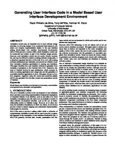
1 Introduction To meet the challenges of the diverse and unpredictable number of computing platforms, ad hoc development of the user interfaces is no longer considered acceptable in terms of the cost and time required for software engineering development and maintenance. There is an increasing interest and adoption of Model-Based User interface Approach [6, 9] due to the applicability of the approach in MPUI development. Today, due to the fact that no method has really been emerged from the various attempts to establish a comprehensive ModelBased approach for MPUI design, a standardization process has been adopted by researchers[8, 9 ], mainly to follow a Model Driven Engineering (MDE) approach by implementing the Model Driven Architecture (MDA) [13] launched by the OMG group [12]. Calvary et al in [8] introduced the CAMELEON Reference Framework; the framework divides the development process into four levels of abstractions (Fig.1)[8, 16].
ISSN: 1790-5117
Fig. 1 CAMELEON Framework Structuring our design process according to this framework and using UsiXML [15] language as the target modeling language supports the creation of MPUIs in a MDE compliant approach [9].
2 Related Work Many model-based UI design approaches have considered MPUI design and development. In this section we will focus on the most recent related work. Dygimes [10] is a run time environment that automatically generates UIs for mobiles and embedded systems, the environment is a user centered approach, similar to our approach; starts the UI design from task specification using the Concur-
299
ISBN: 978-960-474-166-3
Proceedings of the 9th WSEAS International Conference on APPLICATIONS of COMPUTER ENGINEERING
TaskTrees (CTT) formalism [2]. TERESA [7]; also based on the CTT; is a transformational approach that enables the design of multi-device UIs with graphical or vocal modalities. TERESA; similar to our approach; is a transformational approach structured according the CAMELEON Reference Framework [8] and followed a forward engineering process; while we use one task model to derive multiple UIs, TERESA requires the designer to specify many task models by filtering the original task model according to the target platforms. TransformiXML [16] is a UsiXML tool based on attribute graph grammar; the tool follows a transformational approach following transformation at the same level of abstraction for a different context of use. Another work based on UsiXML is an approach called “Graceful Degradation” [11], the approach aims at creating MultiPlatform UIs by splitting an existing user interface designed for the least constrained platform (e.g. a PC) to a more constrained platform (e.g. a mobile phone),the transformations are semi-automatic but do not follow the CAMELEON Framework. We extended the work done in both TERESA and UsiXML by introducing the Dialog-States model [6], which is more concrete than the task model and more abstract than their abstract user interface model. Unlike TERESA and UsiXML, our Dialog-States model gives an explicit design of the navigational model, and gives the opportunity to adapt to context of use at early stages of the design process.
3
UI and the most affecting model in Multi Platform context. One of the major difficulties on designing MPUIs is how to distribute the user interface over the available physical screen space associated with every target device and how to handle the navigation according to this distribution; hence, we are placing dialog modeling (DSM) is in the center of the design process, this also helps to achieve continuity and consistency between the models and to allow designers to predict earlier about the presentation of the user interface. Fig. 2 describes the design process as a four step process supporting forward engineering from the “Tasks & concepts” level to the “Final UI” level as depicted in the CAMELEON Framework: The following sections will explain the steps of the design process; a case study is used to illustrate the process.
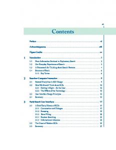
Fig. 2 The design process Step 1: Creation of the task and domain model: The task model is expressed using the ConcurTaskTrees (CTT) notation [4]: The designer uses IdealXML [7] tool that enables the creation of the task, domain model and the mapping between them, Fig. 3 show the CTT for the payment task, for a car rental system. Leaf tasks should be specified using two attributes: userAction and taskItem
The Design Methodology
Our methodology aims at producing multiple Final UIs for multiple computing platforms, at design time. We believe that the navigation structure of the UI is the core aspect of the
ISSN: 1790-5117
300
ISBN: 978-960-474-166-3
Proceedings of the 9th WSEAS International Conference on APPLICATIONS of COMPUTER ENGINEERING
that enable a refined expression of the nature of the task and are essential in the next transformation to derive the AUI model [15, 5]. The userAction indicates a user action required to perform the task. The userAction values are: start/go, stop/exit, select, create, delete, modify, move, duplicate, toggle, view, monitor, convey [14]. These are the same values as for the actionType attribute for Abstract Individual Components at the Abstract User Interface level [14]. The taskItem attribute refers to a type object or subject of an action; which can be: an element, container, operation or a collection of them. For example for the task “EnterName” actionType =”input” and taskItem = “Element”, the mapping model specifies that this task maimpulates an attribute of the domain model.
level of automation based on the structure of the task model and is a limitation of the approach which is more flexible and can be tailored according to the target device screen size. A pragmatic approach will be taken in which usability is emphasized over a completely automated transformation. Thus, transformation from task model to AUI model is done by our semiautomated dialog model; the DSM. To derive the AUI from the task model two intermediate sub-steps are performed: Step 2.1) Task model to DSM mapping: At this step the DSM ; a model based on Harel’s StateCharts [3]; is created. We define a state in the DSM as the set of all tasks that are logically enabled to start their performance during the same period of time; thus will represent a presentation unit in the user interface. This is similar to the concept of Enabled Task Sets [9, 15]. A dedicated algorithm, based on the semantics of the task types and temporal relationships among tasks, automatically compute an initial DSM [6], this model contains the maximum set of states of the DSM [6] since our initial target is devices with very small screen size. Considering the semantics of StateCharts, we identify a start state
Step 2: Deriving the Abstract user interface (AUI): Although we are using IdealXML [5] for specifying the task model, we do not rely on the generated enabled task sets that were defined in [10], nor the AUI presented in the tool. The AUI in IdealXML restricts the navigation since the containment of UI elements corresponds to the user tasks is done based on the level in the task tree; this indicates a
Fig. 3 The task model
ISSN: 1790-5117
301
ISBN: 978-960-474-166-3
Proceedings of the 9th WSEAS International Conference on APPLICATIONS of COMPUTER ENGINEERING
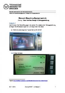
a final state and the transitions between these states are also computed, also in an algorithmic way depending on temporal relationships between the tasks. Fig. 4 shows the initial DSM calculated by the algorithm for the tree in Fig. 3.
(a)
(b)
Fig. 4 The initial DSM The details of the algorithm can be found in our previous work [6]. After computing the initial DSM, the designer can refine this model and/or create one or more Dialog-State models, each for a target platform by merging states; hence the DSM is our initial step in handling adaptation to context of use; (device screen size at this phase); by mapping the same task model to different DSMs. For example the designer can save both DSMs in Fig. 5. Note that in Fig 5(b) the designer combined the three states into one compound state according to target screen size.
Fig. 5 Two possible combinations of the initial DSM mapped to an AUI model. The DSM in Fig. 5(a) will be transformed to an AUI with three containers, the First Conainer will contain two AICs, while for the DSM in Fig 5(b) an AC that embeds three ACs will be created. DSM Construct
UsiXML AUI model construct Basic state AIC Composite State AC Transition abstractDialogControl relationship + AIC with navigation facet Hierarchy abstractContainment relationship
Step 2.2: DSM to AUI mapping: The AUI in UsiXML is composed of Abstract objects: Abstract Containers (ACs) and Abstract Individual Components (AICs) [14, 16], at this step we map composite states to ACs and basic states AICs, then assigning the suitable facets to the AICs, also we define both the navigation and control between AUI elements. Table 1 presents the potential mappings between the two models constructs. According to transformation rules, Each of the DSM in figure 5 will be
ISSN: 1790-5117
Table 1 mappings between the DSM and the AUI in UsiXML Each AIC can be equipped with facets describing its main functionality (input, output, Navigation and control)[14]. These facets are derived from the combination of task model,
302
ISBN: 978-960-474-166-3
Proceedings of the 9th WSEAS International Conference on APPLICATIONS of COMPUTER ENGINEERING
Step 3: Mapping the AUI to Concrete User Interface (CUI) Model: This level is modality dependent, at this level the designer chooses the target modality, currently we only consider graphical modality. In UsiXML the CUI is populated by Concrete Interaction Objects (CIO’s) and Concrete User Interface relationships between them. For graphical modality UsiXML further classifies graphical CIO’s in two categories: graphical containers (GCs) and graphical individual components (GIC). A GC is a graphical CIO that can contain other CIO’s, including other containers. UsiXML's metamodel [14,15] contains a list of 11 types of containers such as: dialog box, menu bar, menu pop-up, tool bar, status bar, window and box. GIC’s are a direct abstraction of widgets found in popular toolkits. For example, UsiXML's checkbox component corresponds to in HTML 4 or JCheckBox in Java Swing. The list of GICs in UsiXML includes: text component, button, radio button, checkbox, combobox, etc. [14]. Dialog control relationship can be defined between both types of interaction objects. We derive the CUI by set of transformation rules: mapping AC to Graphical containers (GCs), AICs to graphical Individual components (GICs), some of these rules are shown in table 3. Many other rules are available for matching the target platform, for example an AIC with input facet and actionType=select can be mapped also to radio button group if the target platform supports this widget. Other rules as resizing rules can be applied; for example to change the font size and picture size. The dialog control relationship at this level is a reification of the dialog control relationship at the AUI, transitions at the DSM which where mapped to AIcs with navigation
domain model and the mappings between them, using transformation rules, as these listed in table 2. UserAction Create Select
TaskItem Element Element
Start
Operation
Convey Start
Element Container
Facet Input Input Navigation / control Output Navigation
Table 2: Mapping between task attributes and AIC facet types Transitions between the states of the DSM are modeled by assuming sequential navigation and Global placement on interaction components (i.e NEXT button is placed in the outer container); that is done by a transformation rule that creates AICs with navigation facet (NEXT, PREVIOUS buttons at the next step) and placing them in the outer Container (line 1517 Fig. 6). At the AUI dialog control between Abstract Objects is ensured by dialogControl relationship, using LOTUS operators (lines 58-.69.Fig. 7)
……………………………………
Fig. 7: Part of the AUI model expressed in UsiXML
ISSN: 1790-5117
303
ISBN: 978-960-474-166-3
Proceedings of the 9th WSEAS International Conference on APPLICATIONS of COMPUTER ENGINEERING
facet will be transformed to NEXTPREVIOUS buttons at this level, that are endowed with graphicalTransition relation[14]. That enables giving them an activate/deactivate power. Two rules are applied here: R1: Endow the OK button with graphicalRelationship type = ”graphicalTransition” and transitionType = ”activate”. R2: Endow the Cancel button with graphicalRelationship type = ”graphicalTransition” and transitionType = ”deactivate”. AUI(AIC) Facet Type Input
Create element
Input
Select element
Navigation
Start operation
Fig. 8 FUI for DSM in Fig. 6(a)
CUI(GIC) create two GICs: An input text and an output text(for the label) create two GICs: A list box and an output text( the label), for every value in the tag create an item in the list box. Create GIG of type button.
Fig. 9 FUI for DSM in Fig. 6(b)
Conclusion In this paper we presented a MDE transformational approach to design MPUI, the design process is structured according to the CAMELEON Reference Framework and the target modeling language is UsiXML. A core model is integrated in the design process to adapt to multiple platforms multiplatform screen size limitations by designer intervention. The approach is more feasible than fully automatic approaches from usability view point. The proposed methodology uses set of tools for model based UI development, storing the models in a model repository allows reusability of the models for new target devices. Future work will focus in combining these tools as a tool chain embedded in a modeling framework, also taking other parameters of the context of use
Table 3 Mapping AUI components to CUI components Step 4: from CUI to Final User Interface (FUI): After the code of the CUI is produced, this code could be either interpreted or compiled by a rendering engine. UsiXML can be rendered by set of rendering engines (e.g. GrafiXML, FlashiXML, QtkXML, InterpiXML)[9]. The FUI for the DSM in Fig. 6(a) and Fig. 6(b), are shown in Fig. 8 and Fig. 9, as previewed by GrafiXML [1] tool.
ISSN: 1790-5117
304
ISBN: 978-960-474-166-3
Proceedings of the 9th WSEAS International Conference on APPLICATIONS of COMPUTER ENGINEERING
model (environment and user) into account, and considering other modalities.
[9] J. Vanderdonckt, Model-Driven Engineering of User Interfaces: Promises, Successes, and Failures, Proc. of 5th Annual Romanian Conf. on Human-Computer Interaction ROCHI’2008 , Bucarest, pp. 1-10, 2008. [10] K. Luyten, T. Clercks, K. Coninx, and J. Vanderdonckt, Derivation of a Dialog Model from a Task Model by Activity Chain Extraction, Proc. Of DSV-IS2003, Spriger-Verlag, pp. 203-217, 2003. [11] M. Florins, F. Montero, J. Vanderdonckt, and B. Michotte, Splitting Rules for Graceful Degradation of User Interfaces, In Proc. of 10th ACM Int. Conf. on User Interfaces Intelligent IUI’2006, ACM Press, New York pp. 264–266, 2006. [12] OMG: The object management Group: http://www.omg.org [13] OMG: Model Driven Architecture available at: http://www.omg.org/mda/mda_file s/02F-SIW-004-OMG.pdf . [14] UsiXML documentation version 1.8.0, available at: http://www.usixml.org/index.php? mod=download&file=usixmldoc/UsiXML_v1.8.0- documentation.pdf [15] Q. Limbourg, , J. Vanderdonckt, ,B. Michotte, and L. Bouillon and V. López , UsiXML: a Language Supporting Multi-Path Development of User Interfaces, Lecture Notes in Computer Science, VOL. 3425, Springer-Verlag, Berlin, pp. 200-220, 2005. [16] Q. Limbourg, J. Vanderdonckt, Transformational Development of User Interfaces with Graph Transformations, Proc. of the 5th International Conference on Computer-Aided Design of User Interfaces CADUI’2004, Madeira, Kluwer Academics Publishers, Dordrecht, 2004.
REFERENCES
[1] B. Michotte, and J. Vanderdonckt, “GrafiXML, A Multi-Target User Interface Builder based on UsiXML,” Proc. of 4th International Conference on Autonomic and Autonomous Systems ICAS’2008 , IEEE Computer Society Press, Los Alamitos, 2008. [2] CTTE: The ConcurTaskTrees Environment http://giove.cnuce.cnr.it/ctte.html, 2009 [3] D. Harel, StateCharts: A Visual Formalism for Complex Systems, Science of Comp. prog., 1987. [4] E.Saleh, A. kamel, and A. Fahmy, “Dialog States a multi-Platform Dialog model”, ECS journal, vol. 33, Sep. 2009. [5] F. Montero, V. Víctor López Jaquero, J. Vanderdonckt, P. Gonzalez, M. Lozano, and Q. Limbourg, Solving the Mapping Problem in User Interface Design by Seamless Integration in IdealXML, Lecture Notes in Computer Science, Vol. 3941, Springer-Verlag, Berlin, pp. 161-172, 2005. [6] F. Paterno, Model-Based design and Evaluation of Interactive Applications. Springer-Verlag, London, 1999. [7] F. Paterno, and C. Santoro, One model, many interfaces, In Christophe Kolski and Jean Vanderdonckt, editors, CADUI 2002, VOL 3, pp. 143-154, 2002. [8] G. Calvary,J. Coutaz, D. Thevenin, Q. Limbourg, L. Bouil-lon, and J. Vanderdonckt, A Unifying Reference Framework for MultiTarget User Interfaces, Interacting with Computers, Vol. 15, No. 3, pp. 289-308, June 2003.
ISSN: 1790-5117
305
ISBN: 978-960-474-166-3