Multicast Routing in Hierarchical Optical Networks Using Collection-Distribution Networks (An Invited Paper) Onur Turkcu1 , Suresh Subramaniam2 , and Arun K. Somani1 1
Department of Electrical and Computer Engineering Iowa State University, Ames, IA 50011 onurturk,
[email protected] 2 Department of Electrical and Computer Engineering The George Washington University, Washington, DC 20052
[email protected]
Abstract. Emerging optical networks have hierarchical architectures with varying capabilities at different levels. Moreover, many applications nowadays require multicast (one-to-many) connections. We propose a network model that has such a hierarchical architecture which is designed for multicast connections. We develop a multi-stage routing scheme which solves the routing problem in different levels of the network for multicast connections. The network model consists of three levels: collection, core and distribution networks. We adopt the lighttrail model in collection-distribution networks which is a convenient way to carry multicast connections. Connection points between the core and collection networks are the edge routers which groom several multicast connections destined to the same distribution network. We evaluate two call acceptance criteria, namely best effort and all-or-none corresponding to total or partial multicast service, respectively. We show using simulations that our multi-stage routing algorithm with light-trails and edgegrooming improves the performance in the hierarchical network model. Key words: multicasting, light-trails, hierarchical optical networks, routing algorithms
1 Introduction The design of optical networks depends on the geographical area coverage which leads to classification into two main categories, namely long-haul or metropolitan area networks. Long-haul networks operate as backbones of nation-wide networks covering large land masses. On the other hand, metropolitan area networks are employed in smaller geographical regions such as cities. Switching technologies and lightpath termination capabilities may differ as well as the wavelength conversion and e-grooming capabilities according to the design of the network.
2
Onur Turkcu et al.
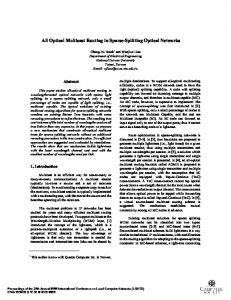
As new network architectures are evolving, applications that utilize the network are also changing. Applications such as video-on-demand, teleconferencing, etc. are all multicast in nature. Multicast connections are defined as one-to-many with a source node transmitting to several destination nodes. Multicasting can be achieved by utilizing light-trees which is a single hop connection from one source to multiple destinations [1]. Light-trees are created using optical wavelength splitting at intermediate nodes and related routing problems involve calculation of light-trees on a certain wavelength based on the network state. Connections with sub-wavelength bandwidth requests result in underutilization of the capacity of wavelengths. In order to overcome this deficiency, traffic grooming combines several connections together in the electronic or optical domain and transmits them on a single lightpath. Traffic grooming is widely studied in the literature [2]. This topic is also considered for multicast connections in [3]. Light-trail technology, proposed in [4], achieves traffic grooming in the optical domain using a uni-directional bus. Every node on a light-trail can transmit to every downstream node. Since each node transmits on a different time slot, time sharing of the available bandwidth is achieved. A convener node initiates the light-trail which is terminated by a terminator node. Connections that can be carried to/from the intermediate nodes depend on the light-trail architecture adopted [5]. Source Light-Trails (SLTs) allow transmission only from the convener node to all downstream nodes, whereas in Destination Light-Trails (DLTs) only the terminator node receives and every other node can transmit to it. In general Light-Trails (LTs), every node can transmit to its downstream nodes on the light-trail. Performance evaluation of all light-trail models and other grooming strategies is done in [6]. A testbed for demonstrating light-trails is developed and evaluated in [7]. Several graph models for routing and wavelength assignment with light-trails are proposed in [5, 8] considering unicast connections. Light-trails also offer a convenient way for carrying multicast connections since any node in the downstream of a convener node can access the same time slot. In [9], given a set of already established light-trails in the network, the authors introduced graph formulations to optimally find the minimum number of light-trails to carry a multicast connection for mesh networks. They also present an optimal greedy heuristic achieving the same objective for ring topologies. Network Description. In this paper, we consider a heterogeneous network architecture consisting of a long-haul core network connecting several metropolitan area (access) networks (see Fig. 1). We divide the access networks into collection and distribution networks (CDNs) since they carry out those tasks. This type of architecture fits well into the emerging fiber optic network designs today since network carriers employ access networks at cities and the communication between cities is carried on the core backbone. Collection network is where source nodes are located and distribution network distributes the corresponding data to their destinations. We note that some of the connections may be local, i.e.,
Multicast Routing in Hierarchical Optical Networks
3
the destination nodes are within the same network. The rest of the connections are global as they travel through the core network to reach other CDNs. A similar network model has been investigated in [10] where the multicast routing problem is studied for a core network with light splitting capabilities. The authors developed an auxiliary graph model to represent the logical topology consisting of light-trees in the core network. They provided algorithms for finding the set of light-trees to carry a multicast connection depending on various design objectives. Different from [10], we also consider the routing problem in CDNs besides the routing in the core network. The solutions we provide for CDNs and core network can be solved independently for each network. We develop distributed routing algorithms for core network and CDNs to find the route of a multicast or unicast connection. We assume light-trail technology is available at CDNs which are connected to the core network through a single node which we call as the edge node. We provide an effective solution in CDNs for multicasting using light-trails. The core network carries only lightpaths and several connections from a collection network to the same distribution network can be groomed at the edge node. Our goal is to find a multicast route that uses minimal network resources in terms of transceivers and wavelengths at each network considered. Our performance metric is the requested multicast bandwidth blocking probability(RMBbp) which captures both the bandwidth and size of multicast call under dynamic traffic model. DLTs/SLTs are used at collection/distribution networks, respectively. Each access network can be used for collection or distribution depending on the multicast call and each of them may also contain local traffic. Therefore, we commonly use LTs for CDNs. The rest of the paper is organized as follows. In Section 2, we describe the network model. In Section 3, we introduce our routing algorithm together with the graph model for light-trails adapted from [5]. We provide a routing algorithm for the core network in Section 4. We then present numerical results in Section 5 and conclude the paper in Section 6.
2 Network and Traffic Model The network model is shown in Fig. 1. There are Γ CDNs numbered from 1 to Γ . A CDN d consists of Nd nodes connected with Ld bidirectional links (two fibers in opposite directions). Let Ωd denote the set of nodes in d. The set of nodes in all such networks is denoted by Ω = Ω1 ∪ Ω2 ∪ . . . ∪ ΩΓ . Light-trail technology is enabled at these nodes having T transmitter/receiver pairs (transceivers). The edge node of CDN d is denoted by Ed which is the connecting point to the core network. An edge node has T transceivers dedicated to the core network and T transceivers dedicated to the corresponding CDN. The core network consists of Nc nodes and Lc bidirectional links. LTs are not available in the core network and nodes other than the edge nodes do not have any transceivers. Therefore, multihopping and traffic grooming is not possible within the core network except at the edge nodes.
4
Onur Turkcu et al.
Multicast connection m is initiated from a source node and it has Dm destinations. We choose Dm uniformly randomly between 1 and maxd where maxd is the maximum possible number of destinations for a multicast connection. When Dm = 1, the connection request is unicast. The source node and destination nodes are chosen uniformly randomly from the set Ω \ {E1 , E2 , . . . , EΓ } without picking the same node twice. Let bwm be the bandwidth request of m. We then have the following definitions for a connection request m. – S : The source CDN that contains the source node s of m. – ∆ : Set of CDNs that include at least one destination of the request. It consists of elements δi (1 ≤ i ≤ |∆|) – Yd : The set of destinations of m in CDN d. YS includes the edge node ES of the source network. |Yd | is the size of this set. Multicast connections arrive at the network according to a Poisson process with a total arrival rate of ρ and they have exponential holding time with mean 1. Upon a connection request arrival, we try to find a route for the multicast connection in the core network and CDNs based on the auxiliary graph model in [5]. The algorithm we propose in Section 3 tries to find the best route for the multicast connection that uses minimum network resources. We consider two interconnection models: 1) the overlay model in which a connection is first routed across the virtual topology (consisting of already established LTs and lightpaths) and then on the physical topology if needed; and 2) the peer model in which a connection can use both layers [5].
T SL
E3
CDN3
SLT
CDN1
ath h tp Lig 1
DLT
CDN4 SL T
E1
s1
E4 Lightpath 2
LT
SL
3
Li g
CDN2
Multicast Connection
E2 DLT
s3
T
ht pa th
s2
Lightpath 4
Color
Source Node
1
s1
2
s2
3
s3
Fig. 1. Network model with several light-trails.
Multicast Routing in Hierarchical Optical Networks
5
We divide the general network routing problem into three sub-problems as follows: 1. Routing Problem 1 (Collection network): Routing the multicast connection from source node s to every node in YS using light-trails. 2. Routing Problem 2 (Core network): Routing the multicast connection from ES to every Eδi for 1 ≤ i ≤ |∆| using lightpaths. 3. Routing Problem 3 (Distribution networks): For every δi in ∆, routing the multicast connection from Eδi to every node in Yδi using light-trails. Upon a multicast call arrival, we run the routing algorithms for every access network δi in ∆ and the core. For routing problems 1 and 3, we develop a routing algorithm that runs on the auxiliary graph of [5]. For problem 2, we create another auxiliary graph and develop our core routing algorithm. We consider two call acceptance criteria as explained in the following section. 2.1 Call Acceptance Criteria The first criterion accepts the call to the network only if connections to every destination in every CDN can be established. This can be described as a all-ornone criterion and can be used for certain type of applications in the network. For example, in a teleconference request between several users, it would be unacceptable if one or more of the users cannot connect to the teleconference from one lecturer. In this case, the source node should be able to the edge node ES and every other destination in YS . The core network should be able to establish connections to every CDN that include destinations and also all of those CDNs should be able to establish connections to every destination within. Otherwise, the call is blocked and dropped. The previous criteria may not be the best strategy depending on the application. For example, in a video-on-demand application several customers requesting the same video are connected with a multicast call. In such a scenario, even if some of the destinations cannot be reached, we would still like to serve the remaining customers. Therefore, the goal of the network operator should be to serve as many customers as possible offering a partial multicast service. We call this call acceptance criterion as the best-effort criterion and the corresponding routing scheme as best-effort routing. In this case, each CDN δi in ∆ tries to establish connections to as many destinations in Yδi as possible. Each CDN can be reached if the core network can support a connection to its edge node and also source CDN can support a connection between the source node s and the edge node ES . The multicast call is established for every such destination that can be reached and the remaining destinations are blocked. In the extreme case that none of the destinations can be reached, the entire call is blocked and dropped.
6
Onur Turkcu et al.
2.2 Performance Metric The common performance metric blocking probability is insufficient to evaluate the network performance for multicast calls since it does not capture the size of the multicast request and its bandwidth. In this paper, we propose to use a new metric called requested multicast bandwidth blocking probability (RMBbp) which captures both those attributes. We first calculate the sum of the product of number of blocked destinations and their requested bandwidth. For example, for a multicast call request m with Dm destinations and bwm bandwidth, this product is Bm × bwm , where Bm be the number of blocked destinations of m. We divide this sum to the total sum of the product of number of destinations and their bandwidth over all multicast requests (e.g., sum of every Dm × bwm ) to get the RMBbp. This metric also allows us to fairly compare the two call acceptance criteria. For all-or-none criterion, Bm is equal to Dm for the blocked multicast calls. Even though, best-effort scheme is expected to have a better RMBbp performance, we note that partial service of multicast calls may result in lower ratio of totally-accepted multicast calls compared to the all-or-none scheme. By accepting partial multicast requests, the network may not be able to accommodate future multicast calls totally which it would have otherwise. If the difference between the two cases is high, it would not be a favorable result for the best-effort scheme. In order to evaluate this, we calculate the metric called not-totally-accepted multicast call ratio which equals to the sum of partially-accepted (or blocked) and totally-blocked multicast call ratios for the best-effort scheme to compare it with the blocked call ratio of all-or-none.
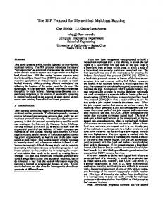
3 Routing in the CDN We first describe the routing algorithm for CDNs according to the all-or-none call acceptance criterion. At the end of the section, we explain how the algorithm is modified for the best-effort criterion. The auxiliary graph in [5] is shown in Fig. 2 for a particular CDN. This is a multilayer graph consisting of W + 3 layers and each of the first W layers corresponds to one wavelength. Layers W + 1 and W + 2 represent the virtual topology (VT) which is defined by the already established light-trails in the network. Subnodes that are on the left/right side of the main node are input/output nodes, respectively. The arcs between the output subnode of node i to the input subnode of node j (1 ≤ i, j ≤ Nd ) on wavelength layer w is created based on the availability of that wavelength in that direction of the link. Layer W + 3 is the grooming layer. For CDN d, this graph contains 2W Nd + 6Nd subnodes. This model supports all the three light-trail architectures, i.e., SLT, DLT, and LT by allowing only the architecture-specific arcs in the VT layer. We call the nodes that are already transmitting/receiving a connection using a transmitter/receiver on a light-trail as active nodes. Therefore, upon a new call arrival, the active nodes that belong to either the source or destination of
Multicast Routing in Hierarchical Optical Networks NODE 1
NODE 2
NODE 3
7
NODE 4
Grooming W+3 Layer W+2 Virtual Topology Layer W+1
Busy Idle
λ2
2=W Wavelength Layer
λ1
1
Wavelength Arcs
Trail Arcs
Fig. 2. Auxiliary graph model.
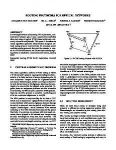
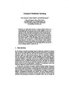
the multicast call can accommodate the new call without the addition of new transceivers. We make proper cost assignment for the arcs that connect to a subnode in the virtual topology layer of the graph depending on whether the node is active or not in the light-trail. BUSY layer of the VT corresponds to nodes that are active and IDLE layer corresponds to nodes that are not active. When multihopping from one light-trail to another is allowed in the VT layer, the light-trail model can perform additional traffic grooming [5]. The technology required for multihop light-trails is also explained in [11]. Now we give an example to illustrate how multihopping can give a route using fewer transceivers for a multicast connection. In Fig. 3(a), initially 3 light-trails are established in the CDN. There is a new multicast connection request between edge node E and two destination nodes 2 and 4. LT2 is established between E and 4. Node 2 is on LT2, however it is not active (i.e., not using a receiver to receive a connection). Suppose that there is enough capacity in the LTs to accommodate the new connection. If multihopping is not allowed and we suppose that this new multicast connection is established on LT2, we would need to use an additional receiver at node 2. In the multihopping case, we can use LT1 to connect E to node 4 without the need of an additional receiver. In the second hop, we can use LT3 from node 4 to node 2 which again does not require any additional transceiver. Overall, if we use multihopping with LT1 and LT3, we can establish the multicast connection without requiring any new transceivers. Minimum Steiner Tree (MST) algorithms are generally used to solve multicasting problems [9]. The solution finds the minimum cost tree including all the nodes in a given set within a graph. However, MST algorithms cannot be applied to our case since the tree solution may not be valid for the following reason. Splitting at a node in one of the wavelength layers would require wavelength splitting capability which is not considered in our model. We show this case in Fig. 4(a). Splitting of the tree from a node in the VT layer would correspond to transmission of two new light-trails for which there may not be enough transceiver resources as shown in Fig. 4(b).
8
Onur Turkcu et al. 1 LT
2
1
2
LT
E
E
LT3
3
2
2
LT3
3
4
4
LT1
LT1 LT1 LT2 LT3
Route of the Multicast Connection
(a)
(b)
Fig. 3. Illustrative example: (a) Light-trails in the CDN before multicast connection request arrival, and (b) The route chosen for the connection.
Node i
(a)
NODE i
(b)
Fig. 4. Illustration of possible MST solutions that contradict our network model with splitting at (a) wavelength layer, and (b) VT layer.
Since a direct tree calculation to cover all of the nodes in the multicast session is not possible, we propose a greedy heuristic that creates light-trails sequentially to cover as many destination nodes as possible in each iteration. The routing decision for the remaining nodes in each step depends on the lighttrails created in the previous step. Initially, we create the auxiliary graph for the CDN, we calculate the shortest paths using Dijkstra’s algorithm to all of the nodes from the source node of the connection or from the edge node for collection or distribution networks, respectively. In the overlay model, we first run Dijkstra’s algorithm on the VT and grooming layers and if a path for the multicast connection is not found, we run it on the wavelength and grooming layers. For the peer model, we run Dijkstra’s algorithm on the entire graph. For each of the destination nodes dj on Yδi , we trace the shortest route to calculate the number of other destination nodes that are already active on the light-trails that dj uses. We denote the set of active nodes along the path to
Multicast Routing in Hierarchical Optical Networks
9
destination node dj by Ij and |Ij | is the size of this set. We find the node with the maximum |Ij | and denote that node by dz . We first establish the connection from source to destination dz on the path calculated using existing light-trails or creating new light-trails. Along this path, other destinations in Ij that coincide with the already active nodes are also covered. Before the second iteration, the auxiliary graph is updated and we run the shortest path algorithm again. We note that established light-trails from the previous step may result in shorter paths for the remaining destinations that are not covered yet. This does not yet affect the bandwidth of these trails in our simulation. We again find dz within the remaining destinations and route the connection. The algorithm stops when all of the destination nodes in the CDN are covered. Whenever one of the remaining destinations becomes unreachable as calculated by the shortest path algorithm, we block the call. We note that while calculating Ij we exclude those nodes that are already covered. We call this algorithm Greedy Multicast Routing (GMR) algorithm and we show its steps in Algorithm 1. The function Dijkstra(s, δi , Model) finds the shortest path from the source node s to every destination within CDN δi . The parameter Model is set to OV1 or OV2 for routing on the virtual or physical links, respectively, in overlay model and it is set to PEER for the peer model. 3.1 Modified GMR Algorithm for Best-Effort Routing Until now, we assumed the call acceptance criteria was all-or-none. Now, we modify the GMR algorithm for best-effort criterion. The difference is that we do not stop the routing algorithm whenever one of the destinations cannot be reached. After every run of Dijkstra’s algorithm, we find the destination dz with the maximum value of |Iz |, that is also reachable (e.g., dist(z) < ∞). We connect the destination dz and update the auxiliary graph and go back to step of Dijkstra’s run. In this way, we continue to connect to the other reachable destinations until each destination dj in Yδi is either unreachable or already connected (e.g., dj ∈ Φ). Modified GMR algorithm returns the number of destinations bm,i that are blocked in CDN δi .
4 Routing in the Core Network Recall that only lightpaths can be established in the core network. However, the edge node that terminate the light-trails on a collection network can electronically groom several multicast connections together on a lightpath if they share a common distribution network. We call this capability as the edge grooming (EG) model. The auxiliary graph we generate for the core network is similar to the auxiliary graph for CDNs except that several arcs are different. Note that multihopping is possible in the core network using an edge node as an intermediate node which is allowed with this graph. When a lightpath is created between two nodes, there is an arc created between the output node of the source to the
10
Onur Turkcu et al. input : Auxiliary Graph G; source node s and set of destination nodes Yδi in CDN δi output: Routing and wavelength assignment for the multicast connection 1 3 4 5 6 7 8 9 10 11 12 13 14 15 16 17 18 19 20 21 22 23 24 25 26 27 28 29 30 31
Initialization: Φ ←− ∅, T rails ←− ∅; while Φ ̸= Yδi do Run Dijkstra’s algorithm to find the shortest path from s to every node in δi ; if Model is Overlay then Dijkstra (s, δi , OV1); if ∃dj ∈ Yδi \ Φ s.t. dist(j) = ∞ then Dijkstra (s, δi , OV2); endif else Dijkstra (s, δi , PEER); endif P athj : shortest path for dj ∈ Yδi with length dist(j); if ∃dj ∈ Yδi \ Φ s.t. dist(j) = ∞ then Block the call; Update the Graph G back to the initial state; endif P athj is on the LTs tr1 , tr2 , ...,trHj where Hj is the number of hops; for dj ∈ Yδi \ Φ do Calculate Ij by tracing P athj ; end Finding the maximum: z = arg maxj |Ij |; Route the connection to dz ; Along P athz , connect every node i ∈ Iz ; for h ← 1 to Hj do T rails = T rails ∪ trh end Update G without allocating bandwidth for LTs (∀tr ∈ T rails); Φ = Φ ∪ Iz end Update G by allocating bandwidth of LTs (∀tr ∈ T rails) used;
Algorithm 1: Pseudocode for the Greedy Multicast Routing (GMR) algorithm. input node of the destination in the VT layer. This arc enables the grooming of an incoming connection request to the existing lightpath. A tree-based solution is still not possible since there is no light splitting in the core network. We take the connection requests one by one from the destination CDNs |∆|, and first route the connection between ES and Eδ1 . We run Dijkstra’s shortest path algorithm on the auxiliary graph. If there is a connection in the virtual topology between ES and Eδ1 with enough capacity to carry the call, then the call is groomed into that lightpath. If a path is found, a lightpath is established between ES and Eδ1 and the auxiliary graph is updated. For the other nodes, we follow the same procedure by first running the shortest path
Multicast Routing in Hierarchical Optical Networks
11
algorithm. The steps of the Core Network Routing (CNR) algorithm are shown in Algorithm 2.
input : Auxiliary Graph Gc ; source edge node ES and set of destination edge nodes Eδi for every CDN δi in |∆| output: Routing and wavelength assignment for the multicast connection in the Core network 1 2 3 4 5 6 7 8 9 10 11 12 13 14 15 16
for i ← 1to|∆| do if Model is Overlay then Dijkstra (ES , Core, OV1); if dist(Eδi ) = ∞ then Dijkstra (ES , Core, OV2); end else Dijkstra (ES , Core, PEER); end if ∃δj j ≥ i s.t. dist(Eδj ) = ∞ then Block the call; Update the Gc back to the initial state; end Route the connection to Eδi ; Update Auxiliary graph Gc ; end
Algorithm 2: Pseudocode for Core Network Routing (CNR) algorithm.
4.1 Modified CNR Algorithm for Best-Effort Routing In the best-effort routing, our goal is to maximize the total number of connected destinations. Therefore, for a multicast call m we first want to establish lightpaths to the CDNs with higher number destinations. For this purpose, we sort the CDNs with descending order with respect to |Yδi |’s. Assume that the ordered CDNs are δ1 , δ2 , . . . , δ∆ . We try to establish lightpaths to the edge nodes of CDNs in this order. If we cannot establish a connection for δi , we move to next CDN δi+1 . Whenever the edge node of Eδi is reachable from the source edge node ES , we run the modified GMR algorithm for δi . However, if GMR returns that all destinations are blocked (i.e., bm,i = |Yδi |), then the connection between ES and Eδi is not established. We note that modified CDR algorithm runs after the GMR algorithm for source CDN S confirms that the source node s is connected to the edge node ES .
12
Onur Turkcu et al.
5 Simulation Results We ran simulations to evaluate the performance of our routing algorithm. The number of call arrivals denoted by num arrivals is 105 or 106 depending on the blocking probability range observed. We use an additional initialization period of 104 trials at the beginning of the simulation. We show the 95% confidence intervals on the curves which are calculated over 10 intervals with num arrivals/10 call arrivals each. For each interval, the period before that interval acts as its initialization period. The Erlang load on the network is denoted by ρ. The core network topologies are the well-known NSFNet and Arpanet. Four CDNs are created randomly having 4, 5, 6, and 7 nodes and their edges nodes are randomly chosen out of the nodes of the core network. The maximum number of destinations in a multicast session (maxd ) is 8. The capacity of a wavelength is 10 units. The bandwidth request of a multicast session is a randomly chosen integer between 1 and 3. We assume the light-trails established at CDNs are all LTs (as opposed to SLTs or DLTs). The number of wavelengths W in the system is 16. In order to see the performance gain achieved by GMR and CNR algorithms separately, we compare our results with two additional cases. In the first case, we restrict CDNs to establish only lightpaths (LPs) to see the performance gain achieved by using LTs. We use the same routing algorithm (GMR) for LPs by modifying the auxiliary graph as follows. In VT layer, the only connections created in this case are between the end nodes of an LP. We note that traffic grooming and multihopping is possible with LPs, too. In the second case, we do not allow edge grooming for the connections through the core network to see the performance gain achieved using edge grooming with our algorithm CNR. We call the case with no edge grooming as NEG. Therefore, the three models that we evaluate are: LT-EG, LP-EG, and LT-NEG. We also compare to call acceptance criteria of best effort and all-or-none, denoted as BE and AoN, respectively. We first plot RMBbp vs. load in Fig. 5 for both topologies with 20 transceivers per node (i.e., T = 20) under overlay model. For both AoN and BE, we see that LT-EG is better than LP-EG with lower loads in Fig. 5(a) for the NSFNet. Specifically, for ρ = 50 the difference is more than an order of magnitude. As the load increases the performance gap between LT-EG and LP-EG narrows down. Light-trails offer more savings by better utilizing the bandwidth of a wavelength at lower loads. Blocking for LT-NEG is much higher than that for the other two cases. Therefore, we conclude that even if we have light-trails available at CDNs, NEG causes a bottleneck in the overall network performance. We note that with the best effort curves have lower RMBbp as expected. The RMBbp of BE gets less than the half of AoN and this improvement stays similar over the observed load range. In Fig. 5(b), we observe a similar behavior for Arpanet. In the load range observed, the performance difference between LT-EG and LP-EG is very close to that of NSFNet. Similarly, the gap increases as the load becomes smaller. The BE curves shows the improvement obtained using best-effort scheme and the difference between the BE and AoN curves for LT-EG gets even higher with
Multicast Routing in Hierarchical Optical Networks
13
0
10
−1
10
−2
RMBbp
10
−3
10
AON LP−EG AON LT−EG BE LP−EG BE LT−EG AON LT−NEG BE LT−NEG
−4
10
−5
10
50
75
100 Load (ρ)
125
150
(a) 0
10
−1
10
−2
RMBbp
10
−3
10
AON LP−EG AON LT−EG BE LP−EG BE LT−EG AON LT−NEG BE LT−NEG
−4
10
−5
10
50
75
100 Load (ρ)
125
150
(b) Fig. 5. Blocking vs. load using overlay model with T = 20 for (a) NSFNet, and (b) Arpanet as core network.
14
Onur Turkcu et al.
lower loads. Our recommendation is to see LTs in CDNs with the best-effort criterion to achieve the best performance. We next compare the best effort and all-or-none schemes in order to evaluate the ratio of the totally-accepted calls (i.e., Bm = 0). For this purpose, we show the the ratio of the not-totally-accepted calls (partially accepted or totally blocked) in BE scheme to the total number of trials. For AoN, we show the blocked call ratio. As shown in Fig. 6(a) for the NSFNet, not totally accepted call ratio for BE is almost the same with the blocked call ratio of the AoN. Thus, the partial multicast service (i.e., best effort) does not degrade the performance in terms of totally accepted call ratio. It just have a slightly higher not-totally-accepted call ratio than the blocked call ratio of AoN. In other words, it has a slightly lower totally-accepted call ratio than AoN. We also note that totally-blocked calls constitute a very small portion of the not-totally-accepted calls. In most cases, BE scheme is able to provide a partial multicast service than rather blocking the entire call. We plot the same metrics in Fig. 6(b) for Arpanet. The ratio of not-totally-accepted for BE is again very close to the blocked call ratio of AoN which is a similar result to NSFNet. Thus, our conclusion is that BE criterion offers the best service without deteriorating the service for totally-accepted calls. We next plot RMBbp vs. number of transceivers (T ) in Fig. 7 for overlay model. In Fig. 7(a), we see that blocking decreases with increasing T for all curves, as expected. With higher T , the blocking difference between LT-EG and LP-EG becomes higher with either BE or AoN. More transceivers allow more traffic grooming capabilities at the intermediate nodes along a light-trail. The difference between the BE LT-EG and AoN LT-EG curves stays the same the whole range of T . This shows that the performance improvement with best effort over all-or-none does not change with the number of transceivers. The same can be said about BE LP-EG and AoN LP-EG curves. Blocking improvement with higher transceivers is also higher in the case of Arpanet as seen in Fig. 7(b). Difference between LT-EG and LP-EG curves is close to an order of magnitude with T = 20. Our conclusion is that the use of light-trails in CDNs is more advantageous with larger number of transceivers and best effort scheme is recommended with any number of transceivers. 5.1 Comparison of Overlay and Peer Models In this section, we plot RMBbp vs. load for both overlay and peer models in order to compare the two in Fig. 8(a) for the all-or-none scheme. We note that LT-EG and LP-EG in peer model have similar performance with LT-EG being slightly better, and they are both much better than both overlay cases. Peer model enables even LP-EG to use many multihopped paths which results in a similar performance to LT-EG’s. LT-EG curve is just slightly better than the LP-EG curve. Therefore, having LTs is not advantageous over having LPs in the peer model since the resources of the network can be utilized more efficiently. However, traffic grooming may be expensive and sometimes limiting. In Fig. 8(b), we plot RMBbp vs. T . Difference between the peer model curves and the overlay model curves first increaseswith higher T until T = 24. After that point, the blocking
Multicast Routing in Hierarchical Optical Networks
15
0
10
−1
10
−2
RMBbp
10
−3
10
−4
10
Not−totally−accepted BE Totally−blocked BE Blocked AON
−5
10
50
75
100 Load (ρ)
125
150
(a) 0
10
−1
10
−2
RMBbp
10
−3
10
−4
10
Not−totally−accepted BE Totally−blocked BE Blocked AON
−5
10
50
75
100 Load (ρ)
125
150
(b) Fig. 6. Blocking vs. load using overlay model with T = 20 for (a) NSFNet, and (b) Arpanet as core network.
16
Onur Turkcu et al.
0
10
−1
10
−2
RMBbp
10
−3
10
−4
10
AON LP−EG AON LT−EG BE LP−EG BE LT−EG
−5
10
8
12
16 20 Number of Transceivers (T)
24
28
24
28
(a) 0
10
−1
10
−2
RMBbp
10
−3
10
−4
10
AON LP−EG AON LT−EG BE LP−EG BE LT−EG
−5
10
8
12
16 20 Number of Transceivers (T)
(b) Fig. 7. Blocking vs. T using overlay model with ρ = 75 for (a) NSFNet , and (b) Arpanet as core network.
Multicast Routing in Hierarchical Optical Networks
17
0
10
−1
10
−2
RMBbp
10
−3
10
−4
10
AON LP−EG OVERLAY AON LT−EG OVERLAY AON LP−EG PEER AON LT−EG PEER
−5
10
50
75
100 Load (ρ)
125
150
(a) 0
10
−1
10
−2
RMBbp
10
−3
10
−4
10
AON LP−EG OVERLAY AON LT−EG OVERLAY AON LP−EG PEER AON LT−EG PEER
−5
10
8
12
16 20 Number of Transceivers (T)
24
28
(b) Fig. 8. Blocking vs. (a) ρ for T = 20 , and (b) T for ρ = 100 with Arpanet as core network.
18
Onur Turkcu et al.
decreases slowly for the peer model. In the peer model, transceivers are utilized very well because of many multihopping opportunities. However, performance starts getting limited by the availability of wavelengths with higher T . Peer model offers a much better performance either with light-trails or lightpaths at the expense of higher information exchange to make the physical topology information available at higher layer.
6 Conclusion We considered a hierarchical network model with collection/distribution networks (CDNs) employing light-trails and attached to a core network. Edge nodes that are the connecting points between the core network and CDNs perform grooming. We investigated the multi-stage routing problem for multicast connections in this network model and proposed routing algorithms for the core network and CDNs. The multicast routing algorithm in CDNs calculates the route using the existing light-trails or creates new light-trails to accommodate the multicast call with minimal network resources. We considered two call acceptance criteria, namely best-effort and all-or-none and we introduced a new performance metric called requested multicast bandwidth blocking probability (RMBbp) to evaluate the performance. We showed using simulations that the use of light-trails improves the performance compared to lightpaths, and grooming at the edge nodes is crucial for better performance. Partial multicast service with the best effort criterion improves the RMBbp and it does not deteriorate the performance significantly for totally serviced calls. Our overall recommendation is to use partial multicast service with the best effort criterion and utilize light-trails technology in CDNs.
Acknowledgment The research reported in this paper funded in part by the Jerry R. Junking Endowment at Iowa State University, NSF projects CNS 0626741 and 0915795. Any opinions, findings, and conclusions or recommendations expressed in this material are those of the author(s) and do not necessarily reflect the views of the National Science Foundation (or another funding agency).
References 1. S. Sankaranarayanan and S. Subramaniam, “Comprehensive performance modeling and analysis of multicasting in optical networks,” IEEE J. Sel. Areas Comm., vol. 21, no. 9, pp. 1399–1413, Nov. 2003. 2. H. Zhu, H. Zang, K. Zhu, and B. Mukherjee, “A novel generic graph model for traffic grooming in heterogeneous WDM mesh networks,” IEEE/ACM Trans. Netw., vol. 11, no. 2, pp. 285–299, 2003.
Multicast Routing in Hierarchical Optical Networks
19
3. R. Ul-Mustafa and A. E. Kamal, “Design and provisioning of WDM networks with multicast traffic grooming,” IEEE J. Sel. Areas Comm., vol. 24, no. 4, pp. 37–52, 2006. 4. A. Gumaste and I. Chlamtac, “Light-trails: A novel conceptual framework for conducting optical communications,” in Proc. HPSR, June 2003, pp. 251–256. 5. S. Balasubramanian and A. K. Somani, “Design algorithms for path-level grooming of traffic in WDM metro optical networks,” OSA J. Optical Networking, vol. 7, no. 8, pp. 759–782, 2008. 6. ——, “A comparative study of path level traffic grooming strategies for wdm optical networks with dynamic traffic - invited paper,” in Proc. ICCCN, Aug. 2008, pp. 267–272. 7. N. Vanderhorn, S. Balasubramanian, M. Mina, R. J. Weber, and A. K. Somani, “Light-trail testbed for metro optical networks,” IEEE Communications Magazine, vol. 43, no. 8, pp. S5–10, 2005. 8. Y. Ye, H. Woesner, R. Grasso, T. Chen, and I. Chlamtac, “Traffic grooming in light trail networks,” in Proc. GLOBECOM, November–December 2005. 9. Y. Li, J. Wang, A. Gumaste, Y. Xu, and Y. Xu, “Multicast routing in light-trail WDM networks,” in Proc. GLOBECOM, November–December 2008. 10. Y. Zhu, A. N. Patel, and J. P. Jue, “A novel graph model for dynamic multicast flow aggregation in optical networks,” in Proc. ICC, June 2009. 11. A. Gumaste, J. Wang, A. Karandikar, and N. Ghani, “Multihop light-trails MLT - a solution to extended metro networks,” in Proc. ICC, June 2009.