COPYRIGHT NOTICE © 2015 IEEE. Personal use of this material is permitted. Permission from IEEE must be obtained for all other uses, in any current or future media, including reprinting/republishing this material for advertising or promotional purposes, creating new collective works, for resale or redistribution to servers or lists, or reuse of any copyrighted component of this work in other works.
Multiperspective Focus+Context Visualization Meng-Lin Wu and Voicu Popescu
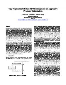
Fig. 1. Conventional visualization of terrain dataset (top) and multiperspective visualization constructed with our framework in top-down fashion (bottom). The viewpoint was modified for two regions individually to reveal a lake (left) and a valley (right). Abstract—Occlusions are a severe bottleneck for the visualization of large and complex datasets. Conventional images only show dataset elements to which there is a direct line of sight, which significantly limits the information bandwidth of the visualization. Multiperspective visualization is a powerful approach for alleviating occlusions to show more than what is visible from a single viewpoint. However, constructing and rendering multiperspective visualizations is challenging. We present a framework for designing multiperspective focus+context visualizations with great flexibility by manipulating the underlying camera model. The focus region viewpoint is adapted to alleviate occlusions. The framework supports multiperspective visualization in three scenarios. In a first scenario, the viewpoint is altered independently for individual image regions to avoid occlusions. In a second scenario, conventional input images are connected into a multiperspective image. In a third scenario, one or several data subsets of interest (i.e. targets) are visualized where they would be seen in the absence of occluders, as the user navigates or the targets move. The multiperspective images are rendered at interactive rates, leveraging the camera model’s fast projection operation. We demonstrate the framework on terrain, urban, and molecular biology geometric datasets, as well as on volume rendered density datasets. Index Terms—Occlusion management, camera models, multiperspective visualization, interactive visualization, focus+context
1
I NTRODUCTION
Most images used in computer graphics and visualization are computed with the conventional planar pinhole camera (PPC) model, which approximates the human eye. Whereas this is essential in applications such as virtual reality where the goal is to make users believe that they are immersed in the scene rendered, researchers in visualization have recognized that the limitations of conventional images are not always warranted. This research path was inspired by artists who have long looked beyond the conventional PPC to achieve compositions that exaggerate scale or avoid occlusions. One limitation of conventional images is a reduced field of view, which has been addressed with panoramic camera models such as fisheyes. A second limitation is that conventional images sample the Meng-Lin Wu and Voicu Popescu are with the Department of Computer Science at Purdue University, West Lafayette, IN 47907. Email:
[email protected],
[email protected]
1
dataset uniformly, oblivious to importance variations within the dataset. Conventional focus+context techniques address this limitation by allocating more image pixels to data subsets of higher importance. A third limitation is that a conventional image samples a dataset from a single viewpoint and occlusions limit the visualization capability of the image. One approach for overcoming occlusions is to rely on the user to change the viewpoint interactively in order to circumvent occluders and to establish a direct line of sight to each data subset of potential interest. One disadvantage of such a sequential exploration is inefficiency: data subsets are explored one at a time, and the navigation path has to be retraced to achieve a systematic exploration of the entire dataset. A second disadvantage is that the user never sees more than a single data subset at a time and connections between subsets that are far apart in the visualization sequence can be missed. The problem is exacerbated in the case of time-varying datasets, where the eloquence of a connection between distant data subsets could be transient. The problem can be alleviated by visualizing the dataset in parallel with multiple conventional images. The user sees several data subsets simultaneously, but the
Fig. 2. Multiperspective visualization that integrates two input views. The user explores the dataset interactively and selects two views of interest (overhead view, left, and views of interest, middle); then the system connects the two views seamlessly in a multiperspective image.
Fig. 3. Multiperspective visualization (left) of an urban dataset showing two targets (red and yellow dots) that are occluded in a conventional visualization (right). The targets are shown where they would be visible in the conventional visualization in the absence of occluders.
Fig. 4. Multiperspective visualization of a protein molecule dataset with three focus regions (top), and conventional visualization (bottom), for comparison. The focus regions have different viewpoints than the overall visualization, revealing the two bonds of the yellow atom.
2
Fig. 5. Multiperspective volume rendering of a density engine block dataset (left) and conventional visualization (right), for comparison. In the multiperspective visualization the viewpoints of the two focus regions are adjusted to provide a visualization along the piston axes.
visualization is discontinuous at the borders of the individual images and the user has to examine one image at the time which reduces the benefits of the parallel visualization. Another approach for overcoming occlusions is multiperspective visualization, which integrates dataset samples captured from multiple viewpoints into a single, continuous “multiperspective” image. The multiperspective image enables parallel visualization without the high cognitive load of the multitude of disparate contexts presented by individual conventional images [29]. Multiperspective visualization can be seen as a generalization of focus+context visualization. Multiple focus regions are visualized simultaneously connected by continuous context, but without the restriction that all focus regions are visualized from the same viewpoint. The challenge is to construct a multiperspective visualization that provides good control over the multiple viewpoints from where the dataset is sampled, while maintaining image continuity, as needed for visualization efficacy, and while maintaining rendering efficiency, as needed to support interactive visualization and time-varying datasets. In this paper we present a flexible framework for interactive multiperspective focus+context visualization. The multiperspective image is constructed by rendering the dataset with a camera with piecewise linear rays. Some of the rays are designed to circumvent occluders and to reach the data subsets of interest, while the remaining rays are designed to connect the data subsets of interest with continuous context. The multiperspective camera is assembled from a small number of camera segments, i.e. simple cameras with linear rays, which enables good control over the viewpoints integrated in the visualization. Moreover, the segments provide fast projection which allows rendering the multiperspective image efficiently, on the GPU, by projection followed by rasterization. We also refer the reader to the accompanying video [36]. The framework enables multiperspective visualization according to three scenarios. Consider a first scenario where the user visualizes a dataset with a high-resolution, large field of view conventional image. The user can select image regions of interest and modify the viewpoint for each individual region interactively to alleviate occlusions. The overall view does not change and it provides continuous context to connect the multiple focus regions (Fig. 1). This scenario is supported with a top-down multiperspective camera constructor that modifies the ray bundle of each focus region. Topdown construction supports multiple disjoint focus regions (Fig. 4).
3
Consider a second scenario where a user explores a dataset through conventional interactive visualization; views of interest are saved as they are encountered, and then they are integrated seamlessly into a multiperspective visualization (Fig. 2). The views of interest appear undistorted as subregions of the multiperspective image. This scenario is supported with a bottom-up multiperspective camera constructor that integrates conventional views. Consider a third scenario where the goal is to avoid occlusions to one or several data subsets of interest, i.e. targets. As the targets move, the visualization adapts automatically to keep the targets visible (Fig. 3). The targets are shown where they would be visible in the conventional image in the absence of occluders, which conveys to the user the correct direction to the target. When the targets move to locations where they become visible, the multiperspective visualization reverts automatically to a conventional visualization, which can be used as is since it does not suffer from occlusion. We demonstrate our multiperspective framework in the context of terrain (Figs. 1 and 2), urban (Fig. 3), and molecular biology (Fig. 4) datasets. Since our multiperspective visualization approach is based on an intervention on the underlying camera model, our approach ports straightforwardly to volume rendering of density datasets by ray casting (Fig. 5). 2
P RIOR W ORK
The more 3D datasets grow in complexity, the more occlusions stemming from the single viewpoint restriction of conventional images become a limiting factor in visualization. Occlusions are an open research problem that has been approached from many directions [11]. We limit the discussion of prior work to deformation and multiperspective techniques that are most relevant to our approach. Gaining an unobstructed line of sight to a data subset of interest can be done by deforming the dataset. The idea was first used in the context of 2D data visualization, e.g. in the context of graph visualization [32], and it was subsequently extended to 3D datasets, e.g. in the context of short route [10] or car navigation [23, 30] visualization. The goal is to achieve the desired occlusion alleviation by deforming the dataset as little as possible. The deformation approach is the dual of the multiperspective approach. Visualizing a distorted dataset with a conventional camera can be seen as visualizing the original dataset with a multiperspective camera. For example, the multiperspective image in Fig. 3 could be obtained by distorting the urban dataset and then visualizing it with a conventional camera. For volumetric datasets, we can alternatively distort the intermediate sampling agents [18]. The difference is that multiperspective visualizations are constructed by modifying the underlying camera model. The occlusion alleviation effect is designed with great control directly in the image domain, as opposed to indirectly in the 3D dataset. Multiperspective visualization originates in art, where the single viewpoint constraint is occasionally abandoned in the interest of artistic expression, effects that were replicated by computer graphics systems [2]. One practical application is to generate panoramas that alleviate occlusions and emphasize important landmarks and terrain features as needed for example for hiking and skiing maps [9, 12, 16]. This prior work handles height-field terrain dataset, with regions of interest known a priori, and it automates the expertise of professional illustrators. Multiperspective images have also been used to integrate photographs taken from different viewpoints (e.g. street panoramas [1, 28]). In 2D animation, a single multiperspective panorama provides an animation sequence by sliding the frame rectangle over the panorama on a predefined path [33]. Both street and 2D animation panoramas are limited to special scenes. Compared to these panorama techniques, our approach allows for interactive exploration of the dataset in search of regions of interest that might not be known a priori. Furthermore, the datasets are not
restricted to height fields, and the focus regions are imaged without distortion. Like conventional focus+context visualization, we have the goal of an unequitable distribution of image samples in favor of the focus regions, whereas panoramas excel at pursuing visualization comprehensiveness. The generality and flexibility of multiperspective visualization increased through innovations at camera model level. Multiple center of projection images [26] are obtained by rendering a 3D dataset with a one-column camera that slides along a path (i.e. a push-broom camera). Samples from thousands of viewpoints are integrated into a continuous image. The user has good control over viewpoint selection by designing the acquisition path. However, rendering the image is too expensive for interactive visualization or time-varying datasets, as it involves one rendering pass for each image column. Our multiperspective rendering framework relies on a more efficient parameterization of the ray space based on a few (i.e. 10-20) camera segments, which provides the needed occlusion alleviation flexibility without sacrificing rendering performance. The general linear camera (GLC) [34] is at the other end of the multiperspective camera complexity spectrum by possibly being the simplest non-pinhole camera. The rays of the GLC are obtained by interpolating three input rays, and in the case of multiple GLC’s, by interpolating the rays from all GLC’s which overlap on the image plane [35]. The GLC provides fast projection, which ensures rendering efficiency. Given a 3D point inside the GLC frustum, one can compute the barycentric coordinates of the point’s projection on the triangular GLC image by solving linear equations. However, the original parameterization of rays does not provide continuity between adjacent GLC’s that share two construction rays. A continuous GLC parameterization has been subsequently proposed [24], which comes at the cost of cubic projection equations. A single GLC doesn’t have the occlusion alleviation capability needed in multiperspective visualization, but we use continuous GLC’s in our framework to model camera segments, as described in Section 3. Occlusion cameras are a family of non-pinhole cameras designed to extend the viewpoint of conventional cameras to a view region [22]. The camera rays are bent at occluder silhouettes to capture “barely hidden” samples, which are samples that become visible for small viewpoint translations. The resulting image is a high-quality aggressive solution to the from-region visibility problem, i.e. it finds most but not all visible samples. Occlusion cameras generalize the viewpoint to a continuum of nearby viewpoints, whereas what is needed for multiperspective visualization is a generalization of the viewpoint to a small set of distant viewpoints. The needed viewpoint generalization is provided by the graph camera [25]. Starting from a conventional planar pinhole camera, the graph camera is constructed through a series of frustum bending, splitting, and merging operations applied recursively. The resulting camera is a graph of PPC segments. The piecewise linear rays are designed to circumvent occluders and to reach far into the dataset. Compared to the graph camera, the camera employed in our multiperspective framework is built from a mix of PPC and continuous general linear camera (CGLC) segments. The CGLC segments enable frustum splitting while maintaining image continuity, thereby overcoming a major shortcoming of the graph camera (see Section 4.1). Graph cameras can only be constructed automatically using a 2D maze with right angle intersections as scaffold, whereas in our framework the multiperspective camera is built automatically, in 3D, to track targets or to integrate conventional input images. Finally, the graph camera does not allow controlling where a data subset of interest is imaged, whereas our framework allows imaging a subset where it would be imaged in a conventional visualization. This enables the user not only to examine but also to locate the subset of interest. Inspired by the nonlinear trajectory of light in proximity of large masses, multiperspective visualizations have been proposed based on curved rays [7, 13, 19, 31]. Curved rays have later been used for visualization outside of astronomy using ray segments connected with Bézier arcs [8]. The advantage of curved rays is that the
4
Fig. 6. Overview of our multiperspective interactive visualization framework. For each frame, the multiperspective camera model is constructed first, in one of three ways, and then the multiperspective image is rendered.
transition from one viewpoint to the next is gradual, which reduces the distortion for objects that are imaged from more than one viewpoint. The cost is a lower rendering performance due to the higher camera complexity. Localized curved ray traversal [6] alleviates this problem, but is unsuitable for deforming the context region. The curved ray camera is a 1D sequence of camera segments and it does not support splitting, which limits its applicability to removing the occlusion for a single target. We use piecewise linear rays, with C0 continuity, but the C1 continuous rays of the curved ray camera [8] could be integrated into our framework for applications where the additional cost is warranted. In conclusion, prior work has demonstrated the potential of flexible visualizations that enable a local changes to resolution and viewpoint. The work presented in this paper is inscribed in the multiperspective visualization line of research. The contributions of this paper include (1) a novel multiperspective camera model that generalizes the graph camera with CGLC nodes, which enables sampling the entire viewing volume continuously and nonredundantly, while still providing the fast projection operation essential to efficient feed-forward rendering; (2) an interactive camera constructor that allows the user to define several nonoverlapping focus regions and to tune the viewpoint for each focus region independently, while maintaining visualization continuity to the context region; (3) a top down and a bottom up camera constructor that allow splitting a root PPC into multiple perspectives as well as merging several PPCs into one common perspective; (4) a target tracking constructor that builds the camera model to ensure data subsets of interest remain occlusion free as the visualization camera or the data subsets move. 3
M ULTIPERSPECTIVE C AM ERA
Fig. 6 gives an overview of our framework. For each frame, the multiperspective camera model is constructed first. The camera model can be constructed with user input using a graphical user interface. The camera model can also be constructed automatically in top-down fashion, in bottom-up fashion, or to track data subsets of interest, i.e. targets. The camera model is interpolated with the camera of the previous frame to limit the magnitude of frame to frame camera model changes or with a conventional PPC in order to revert the multiperspective visualization back to a conventional visualization. Then geometry datasets are rendered by multiperspective projection followed by conventional rasterization, and density datasets are volume rendered by ray casting. In this section, we first describe the multiperspective camera model, we then describe how 3D datasets are rendered with the camera to obtain multiperspective images, and finally we describe how the camera is constructed in one of three ways to support interactive multiperspective visualization.
Fig. 7. Camera model that integrates two conventional images with viewpoints V1 and V2 into a multiperspective image. The green camera segments are implemented with conventional planar pinhole cameras. The orange camera segments are implemented with continuous general linear cameras. The rays are piecewise linear, e.g. L0L1L2L3 and R0R1R2R3.
3.1 Camera Model A camera model is a function that assigns a ray to each image plane sampling location. We have designed a multiperspective camera model based on the following considerations. Flexibility; the camera should be able to integrate conventional PPC frusta in order to generate a multiperspective image that shows subsets of interest undistorted, each from its own viewpoint. Moreover, the camera should support a smooth, gradual change of the perspectives it integrates to enable effective interactive exploration of a dataset where users change the regions on which they focus, and to enable the visualization of a dynamic dataset, where the regions of focus can move over time. Continuity and non-redundancy; the camera rays should sample the entire space subtended by the regions of interest, without gaps, in order to connect the images of the regions of interest with continuous context. Like in conventional focus+context visualization, continuity is important to show correctly the connection of the focus region to the context. Visualization discontinuity would place a significant additional cognitive load on the user who has to establish mentally the connection between the focus region and the context. Each point in the sampled space should be sampled by exactly one ray. This implies rays cannot intersect or, equivalently, the camera model projects one point in space to one point on the image. Projection efficiency; given a 3D point inside its frustum, the camera model should provide a fast method for computing the image plane projection of the point in order to support efficient rendering on the GPU by projection followed by rasterization. Fig. 7 gives a 2D illustration of our multiperspective camera model. A root PPC segment a, with viewpoint V0 is used to integrate two leaf PPC segments, b and c with viewpoints V1 and V2. Segments b and c sample the data subsets of interest; they are connected to a with camera segments e and f, each implemented with two continuous general linear cameras (CGLC). Using Fig. 7 again, camera segments f and g sample the dataset in between the subsets of interest to connect the two images with continuous context. Each of them is implemented with two CGLCs. The camera has piecewise linear rays. Ray L0L1L2L3 has three segments, one for each of the camera segments it traverses. Line L2L3 passes through V1, and line L0L1 passes through V0. The far planes F0F1, F1F2, and F2F3 define the far boundary of the camera. CGLC camera segments are the simplest camera segments that tile seamlessly both laterally and longitudinally. A CGLC segment can act as a wedge in between two conventional camera segments to achieve a smooth transition. CGLC segments can be stacked to change ray direction as needed for occlusion alleviation.
5
Fig. 8. Continuous general linear camera frustum. The endpoints L1 and L2 of ray L1L2 have the same barycentric coordinates in triangles A1B1C1 and A2B2C2. 3D point P projects at L1.
The camera model allows tuning the percentage of the multiperspective image pixels allotted to each subset of interest (b and c) and to the context (g), by changing how many of the rays of a are routed to each of the connecting camera segments d, f, and e. Fig. 7 shows a typical case where the context g is sampled at low resolution in favor of the subsets of interest b and c. The multiperspective camera can morph to a conventional PPC by straightening its piecewise linear rays to become single line segments. This is achieved by gradually translating V1 and V2 to V0 and by aligning the connecting camera segments d, f, and e with rays from V0 (Fig. 7). In summary, our multiperspective camera is a graph camera [25] where some of the camera segments are CGLC [24] segments. The CGLC segments allow sampling the entire viewing volume continuously and non-redundantly. 3.2 Rendering by projection & rasterization A 3D dataset modeled with triangles is rendered on the GPU by projection followed by rasterization. 3.2.1 Projection Given a 3D point P, the point is projected with each camera segment until a valid projection is found. A projection is valid if P is inside the frustum of the camera segment. PPC segments use the conventional projection. Fig. 8 illustrates the projection of a point P with a CGLC frustum. The CGLC rays, which have non-concurrent lines, travel from A2B2C2 to A1B1C1. Projection has to find the ray through P, to compute the intersection L1 of the ray with A1B1C1, and then to map L1 to the multiperspective output image. First we find a plane through P that splits the CGLC construction ray segments A1A2, B1B2, and C1C2 in the same ratio t: 𝑡=
𝐴1 𝐴 𝐵1 𝐵 𝐶1 𝐶 = = 𝐴1 𝐴2 𝐵1 𝐵2 𝐶1 𝐶2
Eq. 1
Parameter t is computed by solving a cubic equation. Once t is known, points A, B, and C are known, and one can compute the barycentric coordinates (α, β, γ) of P in triangle ABC. (α, β, γ) are found by inverse barycentric interpolation, which implies solving a quadratic. Then the projection L1 of P onto A1B1C1 is computed as: 𝑳𝟏 = 𝛼𝑨𝟏 + 𝛽𝑩𝟏 + 𝛾𝑪𝟏
Eq. 2
The projection is valid iff 0 ≤ t ≤ 1 and the barycentric coordinates (α, β, γ) satisfy α, β, γ ≥ 0 and α + β + γ = 1. The continuity condition requires that neighboring CGLC frusta tile seamlessly, and the non-redundancy condition dictates that there can
Fig. 9. Multiperspective camera model with the structure shown in Fig. 7 constructed in bottom-up fashion for the scenario shown in Fig. 2. The green, blue, and red frusta correspond to camera segments a, b, and c in Fig. 7.
be at most one valid projection for each point in the data space. This implies that no two frusta intersect, and all frusta are convex. Once a valid projection is found, the projected point L1 can be projected recursively with each camera segment upstream along the path to the root segment. The final barycentric coordinates then linearly map to the multiperspective output image coordinates for P. However, one does not need to project recursively the point P. Instead, we map the vertices of the near face of each camera segment to the multiperspective output image during camera construction. Using Fig. 8 again, let (uA, vA), (uB, vB), and (uC, vC) be the output image coordinates of A1, B1, and C1. Then the output image projection (u, v) of P is computed as: (𝑢, 𝑣) = (𝛼𝑢𝐴 + 𝛽𝑢𝐵 + 𝛾𝑢𝐶 , 𝛼𝑣𝐴 + 𝛽𝑣𝐵 + 𝛾𝑣𝐶 )
Eq. 3
3.2.2 Rasterization The projection of a triangle contained by a CGLC segment has curved edges. We approximate CGLC rasterization with conventional rasterization and we control the approximation error by subdividing any large triangle offline. Visibility is computed using the regular depth test. The z value used is the fractional parameter t that locates the 3D point within its camera segment, plus the camera segment index i. Camera segments are depth indexed from the root to the leaf segments. In Fig. 7, a has depth index 0, d, f, and e have depth index 1, and b, g, and c have depth index 2. 3.3 Rendering by ray casting For some visualization techniques, such as volume rendering [14], the multiperspective image cannot be computed by projection followed by rasterization. To support such techniques, one has to be able to compute the piecewise linear ray for a given image plane location. Computing the ray is similar to the projection operation, but this time we move downstream from the root to the leaf camera segments. Using Fig. 7 again, given image plane point L0, the first segment L0L1 of the ray is computed by intersecting V0L0 with the far face of camera segment a. Then, L2 is computed on the far face of d using the barycentric coordinates of L1 on the near face of d. This defines the second ray segment L1L2. Finally, b is a PPC segment and
6
the third ray segment L2L3 is computed by intersecting V1L2 with the far face F0F1 of b. 3.4
Camera Construction
We have developed three methods for constructing the multiperspective camera. 3.4.1 Bottom-up Construction In bottom-up construction, the user navigates a conventional PPC through the dataset using the keyboard for translation and rotation commands. As views of interest are found, the user saves them as the PPC segments b and c (Fig. 7). The relationship between the views of interest is conveyed with an overhead visualization (left image in Fig. 2, also see video). Once both b and c are saved, the system constructs the remaining segments automatically as follows. V0 is positioned first in front of the near faces of b and c. The field of view of a is chosen to encompass the near faces of b and c and to capture additional foreground and background according to user specified parameters. Finally, segments f and g are constructed to bridge the gap between (d, e) and (b, c). Fig. 9 illustrates the multiperspective camera model from Fig. 7 specialized for the scenario shown in Fig. 2. Only the central row of rays is shown. 3.4.2 Top-down Construction The user starts by navigating a conventional pinhole camera that provides an overview of the dataset. The user can explore a data subset in more detail as follows. First, the user clicks on a dataset point C that will serve as the center of the focus region (Fig. 10). Then, the user constructs a rectangular focus region S centered at C. The focus region defines a camera segment that corresponds to a bundle of rays of the overview camera. The user rotates the camera segment interactively to change perspective on the focus region. The revolution of the camera keeps the focal point C in the center of the focus region. The focus region is padded with a transition region over which the perspective reverts gradually and continuously from the perspective of the camera segment to the main perspective of the overview camera (Fig. 4).
conventional PPC. Larger shifts correspond to larger weights. When targets do not overlap in the image plane, the projection of a vertex is affected by at most one target, and the vertex is projected as in the case of a single target. When two targets overlap, the preliminary and final projections of a vertex at the region of overlap are the same. 4
Fig. 10. Top-down construction around point C, the center of focus region S. The lines of the bundle of rays in the focus region converge at viewpoint V1, which rotates around C by user input. The transition region (grey) gradually reverts the perspective to the main viewpoint V0.
3.4.3 Target Tracking Construction The construction of the multiperspective camera for tracking a single target is illustrated in Fig. 11. The target T is occluded from V0. In the absence of the occluders, T would be visible at P. The construction algorithm reroutes the rays of the pixels around P to go around the occluders. This way the target is visible in the multiperspective image at P, and the occluders are “pushed downwards” (i.e. to the bottom of the image). The rays are rerouted using four camera segments a, b, c, and d. The neighboring camera segments (grey) transition back to the planar pinhole camera, encapsulating the perturbation needed for target tracking. All camera segments have parallel near and far base planes. For projection, plane ABC (Fig. 8) is simply constructed parallel to the base planes, which saves having to solve the cubic equation to find parameter t (see the Projection Section 3.2). Segment d has the original viewpoint V0 so T is seen as it would be seen in the absence of occluders. Multiple targets can be tracked at once, and the targets can converge and then diverge again (see Fig. 3 and video). We do not construct one complex multiperspective camera that removes occlusions to all targets. Rather we construct one multiperspective camera for each target independently and compute the final projection of a vertex by projecting the vertex with each camera and by computing a weighted average of the preliminary projections. The weight of a preliminary projection is based on how much the projection is shifted from where the vertex would project with a
Fig. 11. Multiperspective camera avoiding the occlusion of target T. T would be visible at P in the absence of occluders. The bundle of rays around P is routed just clear of the two occluders (tall and short black rectangles) hiding T.
7
R ESULTS
AND
D ISCUSSION
We have tested our approach for managing occlusions in three scenarios and with several datasets. We first discuss the occlusion alleviation capability of our approach. Then we discuss the multiperspective rendering performance achieved, which is important for interactive visualization. Finally we discuss limitations. 4.1 Quality The major design concerns for our multiperspective visualization framework are visualization construction flexibility and image continuity. As shown in the images in this paper and in the accompanying video, flexibility has been achieved through a camera model that allows modifying the viewpoint for individual regions of a given image, connecting conventional images with continuous context, and tracking one or more targets while avoiding occlusions. Fig. 12 shows that our framework can connect two conventional images with opposite views into a continuous image, whereas a similar image rendered with the prior work graph camera framework [25] suffers from discontinuities which cannot always be hidden behind geometry. As shown in the accompanying video, in a graph camera visualization, an airplane flying above the city disappears and reappears twice as it crosses the discontinuities. In our visualization, the airplane is visible at all times. We achieved this improvement by using CGLC frusta that can perform a split of perspective while sampling the entire space in between the outgoing branches without leaving any void; the PPC frusta used by the graph camera cannot perform the split operation without voids, which result in visualization discontinuity. Fig. 13 shows that our framework can reveal a target hidden in a heavily occluded dataset with only minimal image distortions. The framework supports multiple moving targets which can converge to the same image region and then diverge again. Compared to the curved ray camera [8], which supports target tracking only through sequential multiple viewpoints, our target tracking framework brings two improvements. First, by using flexible CGLC frusta which tile laterally, one can connect the target tunnel to the undistorted peripheral frustum seamlessly, as shown by the grey shaded area in Fig. 11. Second, the flexible CGLC frusta allow projecting the target itself and its background onto the image plane at the exact undistorted position and scale, as shown in Fig. 3. The curved ray camera visualizes the target at a completely different image location than where the target would be visible in the absence of occluders. Our method is part of the general multiperspective class of occlusion managing techniques. As described in the prior work section, a dual approach for managing occlusions is to deform the dataset such that when viewed with a conventional camera the regions of interest are not occluded. Once the multiperspective camera is defined, one could compute a distorted dataset as follows. Consider dataset vertex V that projects with the multiperspective camera at pixel p. Let z be the depth of V along the multiperspective ray that projects it. Compute the deformed position V’ of V by unprojecting p at z with a conventional camera (i.e. along a straight ray). Rendering the deformed dataset with a conventional camera produces the multiperspective image. One advantage of the multiperspective approach over the deformation approach is in a scenario where the targets for which occlusion should be avoided are not known a priori. In such a scenario, the multiperspective camera provides a convenient way of exploring parts of the dataset without requiring the user to navigate the main camera to each part. Our camera has the ability to extend “branches” to preview dataset regions without the user interface
manipulation and the disorientation inherent to navigating a conventional camera around occluders and retracing one’s steps. The piecewise linear rays simulate translating the camera to reveal the target, providing an intuitive preview of what would be seen if the camera were actually translated. A second advantage is that the leaf camera is a conventional camera so the target of the exploration is always visualized distortion free. Out of all our examples, the target tracking in the urban dataset is probably the easiest to replicate with the deformation approach. Here the targets are known, and deformation would simply shrink the height of all buildings along the line of sight to the target. However, the buildings close to the target would have to be shrunk completely, to street level, which affects their recognisability. For the case in Fig. 13, the deformation approach would have to visualize the occluding building below the target with essentially only a contour of its roof, whereas our visualization achieves occlusion alleviation while conveying the height of the building (Fig. 13, left). Our top-down constructor supports changing the viewpoint for any number of disjoint focus regions (Fig. 4), and the target tracking supports multiple dynamic targets that can overlap (Fig. 3, video). Our approach relies on modifying the rays of the underlying camera used to compute the visualization. Therefore the framework can be leveraged in the context of most visualization techniques. For example, in the case of volume rendering (Fig. 5), the rays of the
Fig. 13. Multiperspective image rendered with our framework that tracks a target in a heavily occluded dataset (left); conventional image with hidden target, for comparison (right).
multiperspective camera can be traced through the volume dataset to integrate opacity like in conventional volume rendering. Like any deformation or multiperspective visualization approach, our technique introduces distortions to make room for the samples of the region of interest that is occluded in a conventional visualization. The distortion is confined to the transition region. Even so, some applications might prefer that the parts of the visualization that deviate from a conventional planar pinhole camera visualization be clearly indicated to the user. We achieve this with one of two modes: a red highlight commensurate with the amount of distortion (Fig. 14, top) and an undistorted wireframe rendering of the parts of the dataset affected by the distortion, overlaid onto the multiperspective visualization (Fig. 14, bottom). 4.2 Performance The timing information reported in this paper was collected on an Intel Xeon E5-1660 3.3GHz workstation with 16GB of memory and with an NVIDIA Quadro K5000 4GB graphics card. The implementation uses OpenGL and Cg [21] GPU shaders. For datasets modeled with triangles, multiperspective rendering is implemented with a vertex shader that implements the multiperspective projection. The vertex is projected with each camera segment until a valid projection is found. Vertices outside the 3D axis aligned bounding box of the camera segment are trivially rejected. We start with the leaf segments (i.e. b, c, and g in Fig. 7), which are the largest and are therefore most likely to contain the vertex. For volume rendering, the fragment shader computes and traces the ray at the current pixel with even steps, integrating opacity and translating it to color using a transfer function. The multiperspective rendering performance of our framework is given in Table 1. Table 1. Multiperspective rendering performance.
Frame rate [fps] Fig. 1 46 Terrain 2,119,522 1,920 x 720 Fig. 2 30 Fig. 3 26 Manhattan 3,691,768 1,280 x 960 Fig. 13 30 Eurotown 3,751,621 1,440 x 1,440 Fig. 12 28 Protein 1,438,992 1,920 x 720 Fig. 4 251 Volume 256 x 256 x 110 640 x 640 Fig. 5 8.9 Dataset
Fig. 12. Multiperspective image rendered with our framework (top) that integrates two opposite views (middle) and image rendered with the prior art graph camera framework for comparison (bottom). Our image visualizes the entire sky, whereas the graph camera image misses parts of the sky at the two vertical discontinuities shown with black line segments.
8
Triangles
Resolution
View
We achieve interactive performance in all cases. Geometry rendering (all rows except for the last one) is much faster than
volume rendering by ray casting (last row). However, volume rendering with a conventional PPC yields only a slightly better frame rate of 9.4Hz, This confirms that the overhead of tracing along piecewise linear instead of linear rays is marginal. Rendering the Protein dataset is much faster than the other datasets because only a small fraction of dataset vertices project inside the focus regions, therefore the majority of the vertices are projected conventionally at a smaller cost. When the cubic projection equation has to be solved, we have found that solving the equation numerically is faster than evaluating the closed-form solution expression. The nonlinear projection of the multiperspective camera implies that rasterization is also not linear. In other words, the nonlinear projection applies not only to the vertices of a triangle, but also to its interior. There are two major approaches to nonlinear rasterization, and we have experimented with both. One approach is to actually perform nonlinear rasterization in the fragment shader. For this, one first has to derive a method for approximating the image plane axis aligned bounding box of the projection of the triangle. Since the projected triangle now has curved edges, the approximation has to consider more than the vertices of the projected triangles. Then, nonlinear rasterization can be performed in 3D, by intersecting the dataset triangle with the ray of each pixel of the axis aligned bounding box and interpolating rasterization parameters using the barycentric coordinates of the intersection point. A second approach is to approximate nonlinear rasterization with conventional rasterization but making sure the projected triangles are small enough. Online subdivision requires a geometry shader that issues a varying and potentially large number of primitives, which is a severe performance bottleneck. Offline subdivision has to be done in view independent way which can result in subdivisions that are either too coarse or to detailed for a particular viewpoint.
Fig. 14. The amount of dataset distortion visualized by a red highlight (top) and by an undistorted wireframe rendering (bottom).
9
We have chosen the approach of offline subdivision. The cost of true nonlinear rasterization is unwarranted for the following three reasons. First, today’s complex datasets are modeled with small triangles who can be rasterized conventionally with good results, without subdivision. Second, the focus regions are imaged with PPC segments where conventional rasterization is accurate, and nonlinear rasterization is only used for regions whose role is limited to providing context. Third, using conventional rasterization implies that there are no changes at the fragment shader, which makes our framework portable to any existing visualization effect. Graph 1 shows that the time needed to render a frame is linear with the number of focus regions. The time to render the dataset conventionally is ~1.3ms, and each focus region adds 0.8ms.
Graph 1. Frame time as a function of number of focus regions, for the Protein dataset shown in Fig. 4.
4.3 Limitations There is no fundamental limitation on the number of perspectives integrated using our framework. The top-down constructor supports any number of focus regions, and the target tracking constructor can handle multiple dynamic, possibly overlapping targets. However, all constructors presented here require that the camera segments be disjoint, which is harder and harder to achieve when the number of perspective increases. Overlapping camera segments translate to repeated visualization of the primitives located at the region of overlap, and such redundant visualization might not be useful. Supporting redundant visualization with good performance is difficult because each vertex can have a variable number of projections. Moreover, each of three vertices of a triangle can have a different number of projections (i.e. some vertices are inside more camera segments than others), and projecting such a triangle requires clipping with individual camera segments. The multiperspective visualization effectiveness decreases as the number of perspectives increases. First, the user interaction required to define camera models with many perspectives becomes complex. Second, the number of display pixels allotted to each perspective decreases, which limits the ability to convey clearly each perspective to the user. Multiperspective visualization trades image resolution for resolution along the view direction. Sufficient image resolution is needed for this trade-off to be beneficial. Third, the comprehensibility of the image decreases with the number of perspectives. Another consideration that limits the number of perspectives is the decrease in performance brought by the increase in camera model complexity. Whereas for our examples good performance was obtained by projecting every vertex with every camera segment, scalability with the number of camera segments requires a faster method for determining the camera segment that contains a vertex. The frusta of CGLC segments do not have planar side faces therefore a scheme that subdivides space hierarchically using planes (e.g. a binary space partitioning tree or a kd-tree) will not separate two adjacent camera segments cleanly. Instead, one should use bounding volume hierarchies like the ones developed for ray casting
acceleration. The goal is to achieve an O(log s) projection time, where s is the number of camera segments. Our multiperspective visualizations transition abruptly from one camera segment to the next. Even though the visualization is C0 continuous, the abrupt transition can result in noticeable distortions (Fig. 15, video). We distinguish between two types of camera segment to camera segment transitions. A longitudinal transition is defined at the far face of an upstream camera segment that serves as the near face of the next, downstream camera segment, e.g. segment d to b in Fig. 7. At a longitudinal transition, the piecewise linear rays break from the current linear segment to the next. A lateral transition is through a shared lateral face of two adjacent camera segments, e.g. d and f in Fig. 7. Rays do not traverse these lateral faces and are not affected by the lateral transition. The distortion introduced by longitudinal transitions can be alleviated with two approaches. One approach, demonstrated by the curved ray camera framework [8], relies on rays modeled with Bézier arcs to transition from one viewpoint to the next, solution that can be adapted to our framework. A second approach is to subdivide longitudinally the connective camera segments (i.e. d, e, f, and g in Fig. 7), in order to achieve a gradual viewpoint change. The rays remain piecewise linear, but the ray segments are shorter which reduces the change in direction from one segment to the next. The distortion introduced by lateral translations can be alleviated by subdividing a CGLC segment into a fan of CGLC segments. In Fig. 7, f would have to be subdivided into several segments, with the left–most sub-segment having a ray pattern very similar to camera segment d and with the right-most sub-segment having a ray pattern very similar to e.
Fig. 15. Fragments of the multiperspective visualization from Fig. 12 showing an airplane flying over the buildings. The airplane appears distorted as it crosses from one camera segment to the next (images with red border) and it is not distorted while completely contained by one segment (images with black border).
10
Like any multiperspective or deformation approach, our visualization framework is not well suited for applications where it is important to convey global spatial relationships accurately. Our framework is well suited in an exploratory context where it saves the user to have to navigate around occluders in search of regions of interest or in contexts where the regions of interest are known and the main goal is to keep the targets visible, surrounded by context. Our framework shows the regions of interest free of distortions, as they are imaged with a conventional camera, and the distortions are confined to a transition region, beyond which the original visualization is not perturbed. Finally, an important design concern for the target tracking constructor is to image the target where it would be seen in the absence of occluders, correctly conveying the spatial relationship between the user and the target. Another fundamental limitation inherited from the general class of multiperspective visualization approaches is the requirement that there is an unobstructed path from the user to the target, along which to route the rays to achieve occlusion alleviation. When such a path does not exist, e.g. in the case of an engine with internal parts, our approach has to be used in conjunction with other occlusion management techniques such as explosion [4, 20], cut-away [5], and transparency [17] approaches. 5
C ONCLUSIONS
AND
F UTURE W ORK
We have presented a framework that advances the state of the art in multiperspective visualization: the framework allows constructing continuous multiperspective visualizations by changing the viewpoint for individual focus regions in an image, by connecting input images with continuous context, and by alleviating occlusions to moving targets without distorting or displacing the target subimages. The framework relies on a flexible yet fast multiperspective camera. Whereas a conventional camera has a few parameters with which the application can interact directly (e.g. three rotations, three translations, focal length), our multiperspective camera comprises 10-20 camera segments which amounts to hundreds of parameters. The power of our framework comes from the three constructors that set all these parameters automatically to construct the desired multiperspective visualization. The constructors relieve the application from tedious low-level specification of the camera model, in favor of formulating high-level constraints that are satisfied automatically. We have demonstrated our multiperspective visualization framework in the context of datasets modeled with triangles (i.e. terrain, urban, and bio molecular datasets) and in the context of volume rendered datasets. The framework is readily usable with datasets modeled with other types of geometric primitives, such as spherical particles, as long as the geometric primitives can be tessellated. Future work could focus on supporting higher order primitives without incurring the cost of full 3-D tessellation, for example by applying the multiperspective projection only to the particle center and by resorting to a custom approximate rasterization. The examples shown in this paper and in the video use rectangular focus regions. The smallest building block of our multiperspective camera is a CGLC which has a triangular frustum. Future work could examine defining focus and transition regions of more complex shapes based on polygons tessellated with triangles. We see our work as making a visualization infrastructure contribution that enhances the information bandwidth of images. As such, we foresee that our work brings multiperspective visualization one step closer to becoming a tool for virtually all applications where visualization is needed. Our multiperspective visualization can increase efficiency in a visual search, where using a conventional visualization would require navigating the camera to a potential region of interest and then back, if the region turns out to be a false positive. For example, when examining a density dataset, a physician could change the viewpoint on a subvolume to better examine it, without losing context. A molecular biologist could examine the fit
between a designed molecule and multiple receptor sites that cannot be all imaged with the same conventional visualization due to occlusions. Another direction of future work is the extension to multiperspective visualization of real-world real-time datasets. Consider an urban scene captured with video cameras mounted at intersections, on cars, and on aircraft. The building geometry is known, for example from off-line LIDAR acquisition and conventional CAD modeling, like is the case for our Terrain and Manhattan datasets. The goal is to integrate the real-time video feeds into a multiperspective visualization that avoids occlusions for one or more regions of interest. The geometric model acts like a connection between the various video feeds, indicating the redundant parts of the feeds, as well as how to assemble the feeds in a continuous multiperspective video panorama. Our work advocates abandoning the traditional rigidity of the images used in visualization in favor of flexible images that the user can optimize for each viewpoint, dataset, and application. A CKNOWLEDGEMENTS We thank Jian Cui and Paul Rosen for advising on their earlier work on multiperspective rendering. The protein molecule dataset [15] was obtained from RCSB PDB [3]. The sky cubemap texture was obtained from Roel Reijerse [27] and used under Creative Commons, Attribution-NonCommercial-ShareAlike 3.0 Unported license. http://creativecommons.org/licenses/by-nc-sa/3.0/. We acknowledge support by the Institute of Education Sciences, U.S. Department of Education, through Grant R305A130016, and by the National Science Foundation, through Grant 1217215. The opinions expressed are those of the authors and do not represent views of the Institute of Education Sciences, of the U.S. Department of Education, or of the National Science Foundation. R EFERENCES [1]
A. Agarwala, M. Agrawala, M. Cohen, D. Salesin, R. Szeliski. Photographing long scenes with multi-viewpoint panoramas. ACM Transactions on Graphics, Vol. 25, No. 3, pp. 853–861, 2006. [2] M. Agrawala, D. Zorin, T. Munzner. Artistic multiprojection rendering. Eurographics workshop on Rendering Techniques, pp. 125-136, 2000. [3] H. M. Berman, J. Westbrook, Z. Feng, G. Gilliland, T. N. Bhat, H. Weissig, I. N. Shindyalov, and P. E. Bourne. The Protein Data Bank. Nucleic Acids Research, 28 (1): 235-242, 2000. www.rcsb.org [4] S. Bruckner, M. E. Groller, Exploded view for volume data. IEEE Transactions on Visualization and Computer Graphics, Vol. 12, No. 5, pp. 1077-1084, 2006. [5] M. Burns, A. Finkelstein. Adaptive cutaways for comprehensible rendering of polygonal scenes. ACM Transactions on Graphics, Vol. 27, No. 5, Article 154, 2008. [6] C. D. Correa and D. Silver. Programmable shaders for deformation rendering. ACM SIGGRAPH/EUROGRAPHICS Symposium on Graphics Hardware (GH '07), 2007. [7] C. D. Correa, D. Silver, and M. Chen. Illustrative deformation for data exploration. IEEE Transactions on Visualization and Computer Graphics, Vol. 13, No. 6, pp. 1320-1327, 2007. [8] J. Cui, P. Rosen, V. Popescu, and C. Hoffmann. A curved ray camera for handling occlusions through continuous multiperspective visualization. IEEE Transactions on Visualization and Computer Graphics, Vol. 16, No. 6, pp. 1235–1242, 2010. [9] P. Degener and R. Klein. A variational approach for automatic generation of panoramic maps. ACM Transactions on Graphics, Vol. 28, No. 1, Article 2, 2009. [10] P. Degener, R. Schnabel, C. Schwartz, and R. Klein. Effective visualization of short routes. IEEE Transactions on Visualization and Computer Graphics, Vol. 14, No. 6, pp. 1452-1458, 2008.
11
[11] N. Elmqvist, P. Tsigas. A taxonomy of 3D occlusion management for visualization. IEEE Transactions on Visualization and Computer Graphics, Vol. 14, No. 5, pp. 1095-1109, 2008. [12] M. Falk, T. Schafhitzel, D. Weiskopf, and T. Ertl. Panorama maps with non-linear ray tracing. International conference on Computer Graphics and Interactive Techniques in Australia and Southeast Asia (GRAPHITE '07), 2007. [13] E. Groller. Nonlinear ray tracing: visualizing strange worlds. The Visual Computer, Vol. 11, No. 5, pp. 263-274, 1995. [14] M. Hadwiger, P. Ljung, C. R. Salama, and T. Ropinski. Advanced illumination techniques for GPU volume raycasting. SIGGRAPH ASIA 2008 courses (SIGGRAPH Asia '08), Article 1, 2008. [15] PDB ID: 2XQ3. R. J. C. Hilf, C. Bertozzi, I. Zimmermann, A. Reiter, D. Trauner and R. Dutzler. Structural basis of open channel block in a prokaryotic pentameric ligand-gated ion channel. Nature Structural & Molecular Biology, 17, 1330–1336, 2010. [16] H. Jenny, B. Jenny, W. E. Cartwright, and L. Hurni. Interactive local terrain deformation inspired by hand-painted panoramas. The Cartographic Journal, 48(1), 11-20, 2013. [17] J. Kruger, J. Schneider, R, Westermann. ClearView: An interactive context preserving hotspot visualization technique. IEEE Transactions on Visualization and Computer Graphics, Vol. 12, No. 5, pp. 941-947, 2006. [18] Y. Kurzion and R. Yagel. Space deformation using ray deflectors. Eurographics workshop on Rendering, pp. 21-32, 1995 [19] Y. Kurzion and R. Yagel. Interactive space deformation with hardwareassisted rendering. IEEE Computer Graphics and Applications, Vol. 17, No. 5, pp. 66-77, Sep/Oct 1997. [20] W. Li, M. Agrawala, B. Curless, D. Salesin. Automated generation of interactive 3D exploded view diagrams. ACM Transactions on Graphics, Vol. 27, No. 3, pp. 1-7, 2008. [21] W. R. Mark, R. S. Glanville, K. Akeley, and M. J. Kilgard. Cg: A system for programming graphics hardware in a C-like language. ACM Transactions on Graphics, Vol. 22, No. 3, pp. 896-907, 2003. [22] C. Mei, V. Popescu, and E. Sacks. The occlusion camera. Computer Graphics Forum, Vol. 24, No. 3, pp. 335-342, 2005. [23] S. Möser, P. Degener, R. Wahl and R. Klein. Context aware terrain visualization for wayfinding and navigation. Computer Graphics Forum, 27: 1853–1860, 2008. [24] V. Popescu, C. Mei, J. Dauble, and E. Sacks. An efficient error-bounded general camera model. International Symposium on Data Processing, Visualization, and Transmission, pp.121-128, 2006. [25] V. Popescu, P. Rosen, N. Adamo-Villani. The graph camera. ACM Transactions on Graphics, Vol. 28, No. 5, Article 158, 2009. [26] P. Rademacher, G. Bishop. Multiple-center-of-projection images. SIGGRAPH ‘98, pp. 199-206, 1998. [27] R. Reijerse. Roel z’n Boel. http://reije081.home.xs4all.nl/skyboxes/. [28] A. Román, G. Garg, M. Levoy. Interactive design of multi-perspective images for visualizing urban landscapes. Visualization '04, pp. 537-544, 2004. [29] P. Rosen, V. Popescu. An evaluation of 3-D scene exploration using a multiperspective image framework. The Visual Computer, Vol. 27, Issue 6-8, pp. 623-632, 2011. [30] S. Takahashi, K. Yoshida, K. Shimada, T. Nishita. Occlusion-free animation of driving routes for car navigation systems. IEEE Transactions on Visualization and Computer Graphics, Vol. 12, No.5, pp. 1141-1148, 2006. [31] D. Weiskopf, T. Schafhitzel, T. Ertl. GPU-based nonlinear ray tracing. Computer Graphics Forum, Vol. 23, No. 3, pp. 625-633, 2004. [32] N. Wong, M.S.T. Carpendale, S. Greenberg. EdgeLens: An interactive method for managing edge congestion in graphs. IEEE Symposium on Information Visualization, pp. 51–58. 2003. [33] D. N. Wood, A. Finkelstein, J. F. Hughes, C. E. Thayer, D. H. Salesin. Multiperspective panoramas for cel animation. SIGGRAPH ’97, pp. 243-250, 1997. [34] J. Yu, L. McMillan. General linear cameras. European Conference on Computer Vision (ECCV), Vol. 2, pp. 14-27, 2004.
[35] J. Yu, L. McMillan. A framework for multiperspective rendering. Eurographics conference on Rendering Techniques (EGSR'04), pp. 6168, 2004. [36] Video accompanying this paper is available here: https://www.cs.purdue.edu/cgvlab/popescu/mpr/. Meng-Lin Wu is a Ph.D. student in the Computer Science Department of Purdue University. He received B.S. and M.S. degrees in physics from National Taiwan University, Taiwan in 2005 and 2007 while participating in experimental high-energy physics at KEK, Japan. Prior to joining Purdue, he programmed game physics at International Games System. His research is concerned with occlusion and visibility management in visualization and augmented reality. His current projects include camera model design, 3D scene acquisition and synthesis, and educational gesturing avatars. Voicu Popescu received a B.S. degree in computer science from the Technical University of ClujNapoca, Romania in 1995, and a Ph.D. degree in computer science from the University of North Carolina at Chapel Hill, USA in 2001. He is an associate professor with the Computer Science Department of Purdue University. His research interests lie in the areas of computer graphics, computer vision, and visualization. His current projects include camera model design, perceptual evaluation of rendered imagery and 3D displays, research and development of 3D scene acquisition systems, and research, development, and assessment of next generation distance learning systems.
12