Using a hand-held stylus, the operator moves the stylus laterally, directing the movement of the SPM tip across the sample. The haptic interface enables the user ...
Microsc. Microanal. 4, 504–512, 1999
Microscopy Microanalysis
AND
© MICROSCOPY SOCIETY OF AMERICA 1999
Nanomanipulation Experiments Exploring Frictional and Mechanical Properties of Carbon Nanotubes M.R. Falvo,1 G. Clary,2 A. Helser,2 S. Paulson,1 R.M. Taylor II,2 V. Chi,2 F.P. Brooks, Jr.,2 S. Washburn,1 and R. Superfine1* 1 2
Department of Physics and Astronomy, University of North Carolina, Chapel Hill, NC 27599–3255 Computer Science Department, University of North Carolina, Chapel Hill, NC 27599-3255
Abstract: In many cases in experimental science, the instrument interface becomes a limiting factor in the efficacy of carrying out unusual experiments or prevents the complete understanding of the acquired data. We have developed an advanced interface for scanning probe microscopy (SPM) that allows intuitive rendering of data sets and natural instrument control, all in real time. The interface, called the nanoManipulator, combines a high-performance graphics engine for real-time data rendering with a haptic interface that places the human operator directly into the feedback loop that controls surface manipulations. Using a hand-held stylus, the operator moves the stylus laterally, directing the movement of the SPM tip across the sample. The haptic interface enables the user to ‘‘feel’’ the surface by forcing the stylus to move up and down in response to the surface topography. In this way the user understands the immediate location of the tip on the sample and can quickly and precisely maneuver nanometer-scale objects. We have applied this interface to studies of the mechanical properties of nanotubes and to substrate–nanotube interactions. The mechanical properties of carbon nanotubes have been demonstrated to be extraordinary. They have an elastic modulus rivaling that of the stiffest material known, diamond, while maintaining a remarkable resistance to fracture. We have used atomic-force microscopy (AFM) to manipulate the nanotubes through a series of configuration that reveal buckling behavior and high-strain resilience. Nanotubes also serve as test objects for nanometer-scale contact mechanics. We have found that nanotubes will roll under certain conditions. This has been determined through changes in the images and through the acquisition of lateral force during manipulation. The lateral force data show periodic stick-slip behavior with a periodicity matching the perimeter of the nanotube. Key words: manipulation, atomic-force microscopy, interface, carbon nanotubes, friction, rolling, mechanical properties, nanometer scale
I NTRODUCTION The atomic-force microscope (AFM) measures the topography (Binnig et al., 1986), mechanical properties, and triReceived July 15, 1998; accepted October 26, 1998. *Corresponding author
bological properties (Mate et al., 1987) of a sample surface with subnanometer-scale resolution. The mechanical contact between the AFM tip and surface, along with the precise control of tip-sample forces, allow the AFM to perform nanometer-scale manipulations of particles on surfaces and modification or machining of the surface material. These two capabilities, mapping of topography and surface prop-
Properties of Carbon Nanotubes 505
erties and manipulation, can be performed within the same experiment on the same nanometer-sized system. These complimentary capabilities transform the AFM from an observational tool into a tool with which one can interact with nanometer-scale systems in real time. We have developed an operator interface for an AFM aimed at greatly enhancing the interactive capability inherent to the AFM. The interface, named the nanoManipulator (nM), comprises state-of-the art computer graphics for advanced display of microscope data and a haptic interface that allows manual control of the AFM tip in real time along with force feedback interaction with the surface data. First, the data are rendered as a directionally illuminated surface. In other interfaces, this representation is routinely generated off-line for presentation purposes. We use a highperformance graphics computer (Onyx; Silicon Graphics Inc., Mountain View, CA) to generate the rendered images in real time so that the operator has a clearer understanding of the sample topography. Second, the real-time manual control of the AFM tip is implemented through use of a hand-held stylus (PHANToM; SensAble Devices Inc., Vanceburg, KY). We present here a brief description of the system and its unique capabilities. We also describe examples of sophisticated manipulation experiments made possible by the nM. We present in particular experiments performed on carbon nanotubes (CNTs) in which the nM is used to explore the mechanical and fictional properties of these systems.
I NSTRUMENTATION
AND
M ATERIALS
Nanomanipulator Graphics Typically, AFM data are presented to the user in real time through a color-scale representation of the data where the surface is viewed from directly above. With our system, the data are presented as a directionally illuminated surface from a changeable three-dimensional (3-D) perspective (Fig. 1B). Presenting a 3-D mapping while the experiment is proceeding provides a more intuitive way of looking at the data and leads to quicker understanding of the subtleties of the surface topography. Since topographical data are presented as topography, color can be used for some other data set such as friction, compliance, etc. Two data sets can be presented through different mappings (e.g., color and height) on the same surface and spatial correlation between
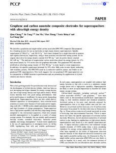
Figure 1. A: User holds the haptic stylus in his right hand while using the nM system. The stylus is connected through a mechanical linkage to motors that supply the force-feedback for feeling the surface topography. The glasses he is wearing provide threedimensional (3-D) visualization and head-tracking for realistic rendering of the surface topography. B: 3-D representation of atomic-force microscopy (AFM) data. A carbon nanotube is depicted in this real-time 3-D rendering of the AFM data. The white triangle indicates the position of the AFM tip when manual control is employed. The position of the icon relative to the features represented in the 3-D view is controlled by the hand-held stylus (PHANToM). The topographical features are then ‘‘felt’’ as the tip is dragged across the surface.
data sets can be easily assessed. Other mapping channels such as contour lines are available for additional simultaneous data sets. A description of the graphics hardware and the details of its incorporation into this system are published elsewhere (Finch et al., 1995; Taylor et al., 1993). Haptic Interface We have also implemented real-time manual control of the AFM tip through use of a hand-held stylus. As the user moves the stylus laterally through some chosen trajectory (Fig. 1A), the AFM tip is moved through an equivalent lateral trajectory (scaled down by a factor of 107) on the sample surface. Of course, since the same tip is used for imaging and manipulation, the user cannot acquire the sample topography and have real-time tip control at the same time. In a typical sequence, the microscope first undergoes a computer-controlled raster to acquire the largerscale sample topography, which is then displayed on the video screen. The user then switches to manual control, with an icon positioned over the raster image to indicate the location of the tip on the sample (Fig. 1B). The hand-held stylus, which controls the tip position, is
506
M.R. Falvo et al.
connected to a mechanical linkage that allows the computer to apply forces to the user’s hand. In our current implementation, when the user has manual control of the lateral position of the sample, the z-axis loop is left to maintain a constant deflection as in normal AFM operation. The user’s hand is guided up and down in response to the local sample height. The height data are then displayed visually and haptically as a virtual surface on which the user can ‘‘feel’’ the topography of the sample surface. This allows the user to find a particular topographical feature on the sample by touch. Non-Contact/Contact Switch A large, dynamic range of tip-sample forces is required to perform controlled manipulation of soft samples. Low forces are required during imaging so that the sample remains undisturbed, while higher forces are required during modifications so that the sample can be pushed or modified. For all of this work, the AFM was operated in two modes: a high-amplitude oscillating mode for nondestructive imaging and a constant force ‘‘contact’’ mode for modifying the sample. In the oscillating mode, the tip is tapped gently against the sample with the oscillation amplitude maintained, effectively minimizing lateral forces that can tear soft biological materials. In contact mode, the tip is simply dragged along the surface with the feedback maintaining a constant force. It is important to be able to change from imaging mode to modification mode quickly and transparently, and back again, for two reasons. First, the placement of the tip at the desired site of modification is more accurate as the microscope does not need to be disengaged and re-engaged to change modes. Second, it allows near-instantaneous visual feedback of the progress of the manipulation work. Our commercial AFM provides the oscillating and constant force modes separately, but the ability to rapidly switch between these modes is not available. We have provided that ability using software modifications to our AFM (Discoverer, Topometrix Inc., Santa Clara, CA).
Lateral Force Microscopy The torsional deflection of the AFM cantilever is a measure of the force on the tip parallel to the sample surface typically referred to as the lateral force. As the AFM tip is dragged across the sample surface or as it pushes an object across the surface, the lateral force on the AFM arises from frictional forces at the tip–surface or object–surface interface. Friction
maps of the sample surface can be made simultaneously with the topographical mapping of conventional AFM operation in a technique known as lateral force microscopy (LFM) (Mate et al., 1987). In the past decade, LFM has been used to identify the intrinsic dependence of friction on contact area (Carpick et al., 1996; Sheehan and Lieber, 1996), resolve atomic-scale friction phenomenon, and observe stick-slip motion in nanometer-scale objects (Luthi et al., 1994).
Carbon Nanotubes The structure of a carbon nanotube (CNT) is simply that of a graphite sheet wrapped seamlessly onto itself to form a tube (Iijima, 1991). They exist in both single wall form, SWCNT (Thess et al., 1996) and multiwall form, MWCNT (Ebbesen and Ajayan, 1992), where the tube wall is made of many concentric shells. The SWCNT often comes in a ‘‘rope’’ or ‘‘bundled’’ form (Thess et al., 1996) where many individual tubes are close-packed in parallel. These CNTs are expected to exhibit extraordinary electrical and mechanical properties. The tubular structure takes advantage of the high basal-plane elastic modulus of graphite to produce a fiber predicted to have mechanical properties that surpass those of any previously known material (Dresselhaus et al., 1996). These properties are expected to have an impact in their application to composite bulk materials and as individual entities in nanometer-scale devices and sensors. The predicted sensitivity of CNT properties on structure and defects (Zhou et al., 1994; Yakobson et al., 1996) makes experiments on individual tubes essential to establish their intrinsic response. Samples were prepared by solvent evaporation on mica and graphite substrates from an ethanol solution of raw carbon soot produced from the carbonarc technique (Ebbesen and Ajayan, 1992). Transmission electron microscopy (TEM) data of our carbon nanotube soot show that the tubes are concentric shells with intershell spacing equal to the intergraphene plane spacing in graphite. Precise manipulation of CNT enables a wide range of experiments including tube–tube contact mechanics (Hertel et al., 1998), electrical contact between selected tubes, and the testing of elementary CNT device geometries. Mechanical devices on the nanometer scale will be subject to surface interactions such as vdW and capillary forces which, in comparison to micron-scale systems, will be larger relative to the structural properties of the device elements (Legtenberg et al., 1994).
Properties of Carbon Nanotubes 507
R ESULTS The nM was designed as a tool for manipulating nanometer-sized surface-bound objects as well as for modifying or machining surfaces. The power of this tool is greatest in experiments where properties difficult to observe through other means are revealed through manipulation experiments. We present two types of experiments. In one set of experiments, objects are pushed across the substrate to reveal their frictional and interfacial properties. In a second set of experiments, the nM is used to create deformations in individual nanometer-scale objects to explore their mechanical properties. Stresses can be applied to particular points of the object and the resulting structure can be observed. We present here work in which we performed these experiments on carbon nanotubes, with the hope of furthering understanding of this remarkable material.
Friction Rolling and Sliding In this first set of experiments, we manipulated CNTs on surfaces using the nM and measured the frictional forces involved in the process. A measure of the force required to initiate and to maintain motion gives insight into the interfacial energy and contact mechanics of the contact zone. In a practical context, these properties are relevant in assessing CNTs’ potential use as lubricants, reinforcements in composite materials, and molecular-scale mechanical mechanisms. In a fundamental sense, these experiments begin to answer basic questions about the motion of nanometer-scale objects. Do they roll or slide, and why? What is the physics behind the resistance to sliding or rolling? Wearless nanometer-scale friction is still not completely understood. In the first experiment, we saw evidence of rolling during a manipulation. A large MWCNT on a graphite substrate was selected for manipulation, as pictured in Figure 2A. One end of this tube had a pronounced ‘‘bump.’’ The tube was pushed from the side (perpendicular to its axis) and the tube rolled, as evidenced by the reorientation of the bump. But when pushed past the point where the bump rolls over and contacts the surface, rolling stopped and the tube slid. The topographical evidence showed that the bump remained on the same side with the same roll-wise orientation while the tube was pushed further in the same direction. When the tube was pushed the other way side-on,
the tube rolled over the other way until it was stopped by the bump. A schematic of this is shown in Figure 2B. The lateral force data signals were consistent with this interpretation (Fig. 2C). The diameter of the cylindrical portion of the tube is 39 nm. Its circumference, assuming a perfectly cylindrical shape, is then 123 nm. In this case, however, the signal abruptly changed at 75 nm after pushing began. This was the case for pushing in both directions (rolling both ways). Assuming the tube is rolling on a cylindrical contact region of 39 nm diameter, it rolls through 220° before sliding begins. The unique aspect of this example is the transition from rolling to sliding. The change in the lateral force at this point is dramatic and counterintuitive. Why is the sliding force lower than the rolling stick peaks? This can be explained with an adhesive model for the rolling. As the asymmetric tube rolls, it goes through a series of pull-off events as the contacting regions at different points along the tube’s circumference release from the surface. If the tube is more polygonal than round, different ‘‘faces’’ of the tube will have varying adhesive strength depending on the different contact area of each point along the tube. The pull-off force for a contact zone can be much higher than the force required to slide it. This model relies on the tube’s asymmetry and is hard to apply to the case of a perfectly cylindrical tube. The harder question to answer is why the tube prefers rolling for the initial portion of the motion when the sliding force is lower. This is unclear. Assuming that there are three thresholds involved—the force required to roll the tube, the force required to initiate motion (static friction), and the force required to maintain motion (kinetic sliding friction)—an argument can be constructed that accounts for this behavior. As the tube rolls, it sticks and slips but at no point is the tube sliding. If the threshold force of rolling is lower than the force required to initiate sliding, then the tube doesn’t slide and continues to roll. But if at some point it does begin sliding and the force required to maintain sliding motion is lower than rolling force, then the tube will slide rather than roll. Calculating the expected adhesive force and the expected frictional force lends insight into this issue. Using the van der Waals (vdW) adhesion force for a cylinder on a plane (Israelachvili, 1991), we calculated the force of adhesion for this tube lying on a graphite substrate to be 800 nN. Note that the ∼90 nN stick peaks in the lateral force data are lower than this. It is expected that the rolling stick peaks should be lower than the total pull-off force since the rolling pull-off is an incomplete and gradual pull-off (peeling) pro-
508 M.R. Falvo et al.
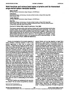
Figure 2. A: Tube with ‘‘bump.’’ On the far right side of the tube, a feature projects out of the cylindrical body. B: Model of the roll-to-slide transition. This is an end-on view of the tube end with the bump. The topographical images indicate that the tube rolls over until the bump contacts the surface; the figure schematically shows what is happening. The tube is able to roll through ∼220° and then begins sliding when the bump contacts on the other side.
C–E: Lateral force during the roll-to-slide transition. C and E show forward rolling and D shows reverse rolling (the x-axis has been reversed for plot D for ease of comparison). In all three cases ∼75 nm of slip-stick signal associated with rolling precedes a flat region associated with the sliding. In each case the tube was rolled from bump contact on one side to bump contact on the other as indicated by the topographical data.
cess. An estimate of contact area based on an estimate of contact width from a modified Hertzian mechanical model (where the vdW adhesion is used as the loading force) yields 5*10−16 nm2. If an estimate of 10 MPa [this is consistent with experimental values (Schwarz et al., 1997)] is used for the frictional shear stress, a friction force of 5 nN results. The sliding force in the three data sets of Figure 2C is not consistent but in each case is lower than 20 nN. The simple vdW adhesion and contact mechanics predict that the adhesive force is two orders of magnitude larger than the sliding force. If the resistance to rolling is due to an adhesive type process, these arguments show that we should expect larger lateral force for rolling than for sliding. In our model, the force of adhesive limited rolling assumes simultaneous pull off all along the tube. This pull-off mechanism could be occurring gradually in a peeling or crack-propagation type mechanism. This would lower the peak force required to roll the tube in the adhesive model. Why the rolling is preferred for the initial portion of the motion is still unclear, however.
SWCNT Rope In the next experiment, we present a case where we manipulated what we believe to be a SWCNT bundle or rope on a mica substrate. The rope was 800 nm long and 15 nm in diameter and is shown in Figure 3A before manipulation. The rope structure was expected to have a much lower bending rigidity than a MWCNT of comparable radius. This is due in part to the very weak intertube vdW interaction that allows the tubes to slide easily over each other under stress. When initially imaging the bundle (Fig. 3A) there was nothing to suggest that this is a bundle. Upon manipulation however, the object showed cable-like behavior or very low apparent bending rigidity (Fig. 3B). MWCNTs of this diameter show much higher rigidity, translating, or rolling, as seen in the last section with little or no bending. Even more interesting, however, was the extraction of one SWCNT from the rope as the rope was dragged across the surface. The adhesion between the individual SWCNT and the mica substrate was high enough to
Properties of Carbon Nanotubes 509
Figure 3. A small-diameter nanotube is seen to emerge from a larger bundle upon manipulation with the AFM. The small tube was eventually completely extracted from the bundle and independently manipulated. This experiment suggests a way to measure the shear stresses in nanotube bundles through calibrated measurements of the extraction force. SWNT, single wall nanotube.
pull it out of the bundle. In subsequent manipulations the smaller individual tube was completely extracted from the bundle. This individual tube was manipulated and moved to verify that it was not simply debris build up from the manipulation process. This experiment indicates a way to measure the intertube shear stress in nanotube bundles through calibrated measurements of the extraction force.
Mechanical The degree of elasticity in the deformation of carbon nanotubes is of principle interest. Because of its high degree of crystalline perfection and ability to avoid catastrophic strain by deforming through buckling modes, the carbon nanotube is capable of large bending without plastic damage (Yakobson et al., 1996). Manipulation experiments have provided an ideal way of exploring the bending and buckling behavior of CNTs (Falvo et al., 1997).
and-forth bending, with radii of curvature as low as 20 nm, the tube in the final image appears to be undamaged. We estimated the maximum local strain in this tube to be ∼16% on the outside tube surface, with a corresponding compressive strain on the inner surface (strain equals the ratio of tube radius to the radius of curvature of the bend). The apparent lack of catastrophic damage to the tube under such large strains is remarkable. We speculate that there are two ways in which the strain was accommodated. First, it has been proposed that MWCNTs contain a significant concentration of defects. It may be that defects in this tube are arranged in an incoherent fashion such that they separate under tensile stress and slide over each other reversibly under compressive stress. Second, strain might be accommodated within a severely distorted, but otherwise connected, graphene sheet. MD simulations of single walled tubes under tensile strain have shown, under certain conditions, breaking strains as large as 30% (Yakobson et al., 1997).
Bending We have observed cases where CNTs survive large strains without gross damage. In Figure 4 an ∼800-nm-long multiwall carbon nanotube (MWCNT) with a 13-nm diameter was bent repeatedly to large strain with no permanent distortion of the tube topography. The sequence of figures illustrates the entire manipulation process of the tube-bending experiment. The nanoManipulator is essential for making this sort of study possible. After each bending manipulation, the tube was imaged. No relaxation was observed during the entire sequence. The surface forces are apparently large enough to keep the tube in place despite the very high strain. Note that despite the repeated back-
Relaxation In other cases presented here, the surface forces were not large enough to keep the tubes in their strained shape, and behavior consistent with elastic relaxation was observed. What follows is evidence taken in AFM snapshots of tube relaxation from states of extreme bending to more relaxed (straighter) states. These examples suggest a remarkable elasticity and absence of plastic damage of these tubes even at very high strains. We emphasize that the AFM scan speed is much lower than the expected elastic response time of a strained CNT. We were not capable of observing the relaxation dynamically but only in ‘‘snap shots.’’ In
510 M.R. Falvo et al.
Figure 4. Sequence of bending manipulations on a 13-nm-diameter multiwall carbon nanotube (MWCNT) on a mica substrate. The sequence is left to right, top to bottom. The tube is subjected to very large strains and yet shows no sign of damage.
some cases, the imaging forces aided in the relaxation process so that a stick-slip type relaxation motion occurred and the tube was imaged at several stages in the relaxation. In the first example, 15-nm gold colloids and carbon nanotubes were co-adsorbed onto a mica substrate from solutions. Figure 5 shows a long tube originally in a straight orientation with a colloid off to the right side of one end and a small cluster of colloids off to the right side of the other end. The tube was pushed toward these two points. When initially manipulated into contact with the cluster, the tube rode up onto them as shown in Figure 5B. On subsequent pushes the cluster acted as a constraint, allowing the tube to slide through in an axial direction but not laterally. The other colloid provided a similar constraint so that as the tube was pushed through the gate formed by the two constraints, it bent more and more as it pulled through, as shown in Figure 5C and D. Eventually, the end at the individual colloid pulled all the way through and upon re-imaging, the tube relaxed (Fig. 5E) to an almost straight orientation, stopping in its relaxation only when it came in
contact with another colloid particle, as shown in Figure 5F. Figure 5E shows the tube reorienting under imaging forces. Here there is no dynamic relaxation occurring, which would presumably occur much too quickly to image with AFM. What is most likely happening is a stick-slip-type relaxation through which the tube, once released from the colloid, is in a metastable mechanical equilibrium: the surface adhesive–frictional forces just barely balance the tube’s elastic restoring tendency. As the tip images the tube, it perturbs the tube and the tube eventually reaches a stable equilibrium when hitting the second colloid stop. This interpretation has interesting consequences for the roles that the surface friction and the colloid-tube interaction must play. Why, for example, does the tube remain stably pinned in a strained configuration and not snap back to straight as in Figure 5B–D? One explanation is that the strain is not high enough in the slightly bent tube to create a surface stress at the interface sufficient to overcome the friction holding the tube in place. In Figure 5C and D, however, the strain is essentially as high as in Figure 5E
Properties of Carbon Nanotubes 511
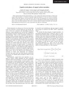
Figure 5. A carbon nanotube is manipulated among co-deposited 20-nm gold colloidal particles. The particles remain fixed on the substrate (A), acting as constraints to the moving nanotube (B). The tube bends as it is pushed through the colloids (C), until it slips free from the lower particle (D). The tube is then unstable under imaging (E) until it relaxes to hit a particle on the far right (F). Detail of E is shown in G, which shows the tube relaxing under imaging forces. After the tube has been released from the lower colloid it remains in a bent shape (a) even as the tip begins to scan over it (the tip scans from top to bottom). The tube slips to a slightly less bent shape (b) and then slips once more, stopping on the colloid at the lower left (c).
where the tube relaxes. It may be that the tube–colloid interaction is sufficient to prevent slipping of the tube back toward a straight shape. Once the tube is released from the lower colloid, it is pinned temporarily by the surface forces. The evidence for this is in Figure 5E, which shows that after the modification following Figure 5D and before the subsequent scan, the tube remains bent. Figure 5G shows the detail of Figure 5E. As the scan passes it over in this configuration it slips once (a), catches at a slightly less bent shape (b), then slips again into the colloid stopper (c). This sticking and slipping aided by the perturbation of the AFM imaging suggests that the friction and the opposing restoring forces in the tube are close to being in balance and may explain the stability of the tube in the first few less severe bends. The example shown here is one of dozens of cases of this behavior that we have observed through manipulation experiments done with the nM. We emphasize again that this material is expected to have a stiffness equal to or
greater than that of diamond and yet is able to withstand strains like an elastomer. The evidence we have presented here does not prove true reversibility, but the relaxation suggests that the tube structure has not been compromised catastrophically even in extreme deformation.
C ONCLUSIONS In the studies described here, we have demonstrated the capabilities of the nM and showed the scientific content in well-designed manipulation experiments. In the friction studies, we observed both sliding and rolling behavior and measured the friction of both processes. We were also able to separate an individual SWCNT from a bundle. Through manipulation, we demonstrated conclusively the remarkable mechanical properties of the CNT, which is predicted by theory and suggested by static TEM and AFM imaging. We showed that an individual tube can be taken through a
512 M.R. Falvo et al.
series of deformation and its mechanical performance can be measured quantitatively.
Israelachvili J (1991) Intermolecular and Surface Forces, 2nd ed. San Diego: Academic Press
A CKNOWLEDGMENTS
Legtenberg R, Tilmans HAC, Elders J, Elwenspoek M (1994) Stiction of surface micromachined structures after rinsing and drying: model and investigation of adhesion mechanisms. Sensors and Actuators A 43:230–238
We thank Otto Zhou for providing the CNT soot material. The NSF, the NIH, and the Office of Naval Research provided financial support for this work.
R EFERENCES Binnig G, Quate CF, Gerber C (1986) Atomic force microscope. Phys Rev Lett 56:930–933 Carpick RW, Agrait N, Ogletree DF, Salmeron M (1996) Variation of the interfactial shear strength and adhesion of a nanometersized contact. Langmuir 12:3334–3340 Dresselhaus MS, Dresselhaus G, Eklund PC (1996) Science of Fullerenes and Carbon Nanotubes. San Diego: Academic Press Ebbesen TW, Ajayan PM (1992) Large scale synthesis of carbon nanotubes. Nature 358:16 Falvo MR, Clary GJ, Taylor RM II, Chi V, Brooks FP Jr, Washburn S, Superfine R (1997) Bending and buckling of carbon nanotubes under large strain. Nature 389:582–584 Finch M, Chi VL, Taylor RM II, Falvo M, Washburn S, Superfine R (1995) Surface modification tools in a virtual environment interface to a scanning probe microscope. In: ACM Symposium on Interactive 3D Graphics. New York: Association for Computing Machinery SIGGRAPH, pp 13–18 Hertel T, Martel R, Avouris P (1998) Manipulation of individual carbon nanotubes and their interactions with surfaces. J Phys Chem B 102:910–915 Iijima S (1991) Helical microtubules of graphitic carbon. Nature 354:56–58
Luthi R, Meyer E, Haefke H, Howald L, Gutmannsbauer W, Guntherodt H-J (1994) Sled-type motion on the nanometer scale: determination of dissipation and cohesive energies of C60. Science 266:1979–1981 Mate MC, McClelland GM, Erlandsson R, Chiang S (1987) Atomic-scale friction of a tungsten tip on a graphite surface. Phys Rev Lett 59:1942–1945 Schwarz UD, Zworner O, Koster P, Wiesendanger R (1997) Quantitative analysis of the fictional properties of solid materials at low loads. 1. Carbon compounds. Phys Rev B 56:6987–6996 Sheehan PE, Lieber CM (1996) Nanotribology and nanofabrication of MoO3 structures by atomic force microscopy. Science 272: 1159–1161 Taylor RM, Robinett W, Chi VL, Brooks FPJ, Wright WV, Williams S, Snyder EJ (1993) The nanomanipulator: a virtual-reality interface for a scanning tunneling microscope. In: Proceedings of SIGGRAPH ’93. New York: Association for Computing Machinery SIGGRAPH, pp 127–134 Thess A, Lee R, Smalley RE (1996) Crystalline ropes of metallic carbon nanotubes. Science 273:483 Yakobson BI, Brabec CJ, Bernholc J (1996) Nanomechanics of carbon tubes: instabilities beyond the linear response. Phys Rev Lett 76:2511–2514 Yakobson BI, Campbell MP, Brabec CJ, Bernholc J (1997) High strain rate fracture, and C-chain unraveling in carbon nanotubes. Comput Mater Sci 8:341–348 Zhou O, Fleming RM, Murphy DW, Chen CH, Haddon RC, Ramirez AP, Glarum SH (1994) Defects in carbon nanostructures. Science 263:1744–1747