The architecture supports load/store access to remote ..... third stage the payload processing. .... case, each processor of the first stage stores the packets in a.
Network processing in Multi-core FPGAs with Integrated Cache-Network Interface Christoforos Kachris, George Nikiforos, Stamatis Kavadias, Vassilis Papaefstathiou, Manolis Katevenis Institute of Computer Science Foundationd for Reasearch and Technology (FORTH) Heraklion, Crete email: {kachris,nikifog,kavadias,papaef,kateveni @ics.forth.gr} Abstract—Per-core local (scratchpad) memories allow direct inter-core communication, with latency and energy advantages over coherent cache-based communication, especially as CMP architectures become more distributed. A multicore FPGA platform with cache-integrated network interfaces (NIs) is presented, appropriate for scalable multicores, that combine the best of two worlds –the flexibility of caches (using implicit communication) and the efficiency of scratchpad memories (using explicit communication): on-chip SRAM is configurable shared among caching, scratchpad, and virtualized NI functions. The proposed system has been implemented in a four-core FPGA. Special hardware primitives (counter, queues) are used for the the communication and synchronization of the cores that are most suitable in network processing applications. The paper presents the performance evaluation of the proposed system in the domain of network processing. Two representatives benchmarks are used; one for header processing and one for payload processing. The system is evaluated in terms of performance and the communication overhead is measured. Furthermore, two approaches for the communication of the processors are evaluated and compared; common queue and distributed queues. Keywords-network processing, (RDMA), multi-core FPGAs
explicit
communication
I. I NTRODUCTION As the number of processing cores per chip increases, so does the need for efficient and high-speed communication and synchronization support, so that applications can exploit the available cores. The memory hierarchies of these multicore systems are based on one of the two dominant schemes - multi-level caches, or directly-addressable local scratchpad memories. Caches transparently decide on the placement of data, and use coherence to support communication, which is especially helpful in the case of implicit communication, i.e. when we do not know in advance which input data will be needed, or who last modified them. However, caches lack deterministic response time, and make it harder to the software to explicitly control and optimize data locality and transfers in the cases when it can intelligently do so. Furthermore, coherent caches scales poorly [1]. On the other hand, scratchpads offer predictable performance which is required in real-time applications. They also offer scalable general purpose performance by allowing explicit control and optimization of data placement and transfers. In the case of scratchpad, the interprocess communication is explicit
meaning that the software (the application, or compiler, or runtime system) is able to indicate physical placement or transfers. The explicit communication is mainly based on remote direct memory accesses (RDMA) that is efficient and it becomes possibly in cases when the producer knows who the consumer will be. The main drawback of the scratchpad is that it reduces the programming efficiency, since extra effort must given to the synchronization and the consistency of the system. Network processors were the first one (along with the GPU) to adopt the multi-core paradigm, mainly due to the inherently parallelism of the network processing applications. Nevertheless, the majority of these systems adopt the memory hierarchy of scratchpads and the interprocess communication is mainly based on simple direct memory accesses (DMA), hence preventing high programming efficiency. This paper presents the performance evaluation in network processing of a novel architecture with cache-integrated network interfaces (NI). This architecture was developed in the context of the “SARC” project [3], to achieve the best of two worlds: the flexibility of caches and the efficiency of scratchpad memories. The proposed architecture allows sharing of on-chip SRAM for caching, scratchpad and NI communication functions at a cache-line granular, all mapped in the application’s virtual address space for virtualization. The architecture supports load/store access to remote scratchpads, and RDMA’s that can be explicitly acknowledged. These communication mechanisms use virtual source and destination addresses and thus provide generalized read and write accesses for explicit communication. In addition, event-responses are implemented as a framework for hardware synchronization mechanisms configurable by software. These responses can increase the programming efficiency in multi-core FPGAs. Three eventresponse mechanisms are supported: command buffers used to initiate multi-word communication; counters that provide barriers for software selected sets of arbitrary size accesses; and multiple-reader queues implemented in scratchpad memory for multi-party synchronization. The rest of the paper is organized as follows: Section 2 reviews related work in the domain of network processing applications and interprocess communication. Section
3 presents the architecture of the merged cache/network interface and the hardware primitives for communication and synchronization. Section 4 describes the implementation platform using an FPGA. Finally, section 5 presents the performance evaluation of the proposed system in the domain of network processing applications. II. R ELATED WORK Configuration of memory blocks has been studied before in the Smart Memories [4] project, but from a VLSI perspective. They demonstrate that using their custom “mats”, i.e. memory arrays and reconfigurable logic in the address and data paths, they are able to form a big variety of memory organizations: single-ported, direct-mapped structures, setassociative, multi-banked designs, local scratchpad memories or vector/stream register files. The TRIPS prototype [5] also implements memory array reconfiguration, but in very coarse granularity. They organize arrays into memory tiles (MTs), which include an on-chip network (OCN) router. Each MT may be configured as an L2 cache bank or as a scratchpad memory, by sending configuration commands across the OCN to a given MT. Network interface (NI) placement in the memory hierarchy has been explored in the past. In 90’s, the Alewife multiprocessor [6] explored an NI design on the L1 cache bus to exploit its efficiency for both coherent shared memory and message passing traffic. At about the same time, the Flash multiprocessor [7] was designed with the NI on the memory bus for the same purposes. Cost effectiveness of NI placement was evaluated assessing the efficiency of interprocessor communication (IPC) mechanisms. Mukherjee et al. [8] demonstrated highly efficient messaging IPC with a processor caching buffers of a coherent NI, placed on the memory bus. Streamline [9], an L2 cache-based message passing mechanism, is reported as the best performing in applications with regular communication patterns among a large collection of implicit and explicit mechanisms in [10]. Moreover, NI Address Translation was extensively studied in the past to allow user-level access, overcoming operating system overheads [11], and leverage DMA directly from the applications [7]. III. C ACHE -I NTEGRATED N ETWORK I NTERFACE M ECHANISMS Explicit communication and synchronization mechanisms work like network I/O devices: the processor initiates operations, polls for status, or waits for input or notifications using memory-mapped control and status registers. To increase parallelism, multiple pending operations must be supported, hence there must exist multiple control and status registers. To reduce overhead, these multiple registers must be virtualized, so as to be accessible in user-mode. To reduce latency, these mechanisms and registers need to be brought close to the processor, at the level of cache memory, as
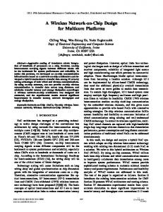
opposed to the level of main memory or I/O bus. This section briefly explains how we achieve all of the above, describing the proposed communication (RDMA) and synchronization (counters, queues, notifications) mechanisms and some typical uses (the detailed scheme was presented in [13][12]. The proposed NI mechanisms are integrated into private –as opposed to shared– caches in order for processors to have parallel access to them. Furthermore, the NI mechanisms are integrated into L2 caches –as opposed to L1 caches or processor registers– in order to provide sufficient scratchpad space for application data and sufficient number of timeoverlapped communication operations, and in order not to affect the processor clock. The prototype implements a phased, pipelined L2 cache (1 access per cycle), a writethrough L1 cache, and selective L1-caching of L2 scratchpad regions. A. Memory Access Semantics: Cache, Scratchpad, Communication As explained above, the advantages possible by scratchpads and multiple memory-mapped communication control/status “registers” all brought close to the processor, into private caches. To support these, memory access semantics must vary. Two mechanisms are used to signal such modified semantics: address translation, to mark entire address regions as explicitly managed (or scratchpad), and cache line state bits, to indicate different access semantics (figure 1). Each address region is augmented with a few bits that mark whether it contains cacheable or directly-addressed (scratchpad) data. Local scratchpad regions are further marked using the state bits of cache lines to mark them as non-evictable. The former obviates tag bit comparison to verify that a memory access actually hits into a scratchpad line in this way, tag bits of scratchpad areas are freed, and they are used for other purposes in the case of communication semantics. Scratchpad lines must still be marked through their state bits, so that hit/miss searches in cacheable space will ignore their tag bits. This combined mechanism allows for runtime-configurable partitioning of the on-chip SRAM blocks between cache and scratchpad use, thus adapting to the needs of the application that is being run at each point in time. The multiple, virtualized communication control/status “registers” that are required, have to be implemented in explicitly managed address regions to indicate their semantics via state and tag bits. Other than plain scratchpad memory, cache lines in scratchpad space can be marked, in their state bits, as having three kinds of such special semantics, as shown in figure 1: (i) communication (RDMA) command/status; (ii) counter, used for synchronization and notification through atomic increment operations; or (iii) queue descriptor, used again to atomically multiplex or dispatch information from/to multiple asynchronously executing tasks.
LM
Local Memory (scatchpad) Data Local Memory (scatchpad) Data
LM Cm
arg.validity flags
Cn
Counter value
Q
head, tail, size
State bits
Tags
RDMA Command arguments event response configuration Queue event resp configuration
Data
wr ....
Tag Update Logic
pckt1
req3
req2
req1
pckt1
pckt1
pckt1
Trigger Response pckt(s)
(a)
(b)
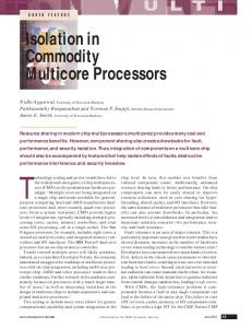
Figure 2. (a) Event Response mechanism integration in the normal cache access flow. (b) Multiple-reader Queue function illustration. Rd Src Addr Dst Addr Ack Addr
read
Normal Scratchpad
Network packets
Memory
Ack Addr Data
Scratchpad
in
c
Counter
ack
Region te immedia d or delaye
dequeued packet
r te
enq
Queue Descriptor
Ack Ack Addr size
un
Data
Wr Dst Addr
co
Dst Addr Ack Addr
data
to
Event responses provide a framework for hardware synchronization mechanisms configurable by software. Eventresponse mechanisms are supported by event sensitive lines (ESLs) with dedicated states as shown in figure 1. On every access to the cache, local or remote, normal cache operation checks the state and tag bits of the addressed line(s). The NI monitors all accesses to ESL’s, called events, reads and updates state stored in the ESL tag, and checks whether some conditions are met, as illustrated in figure
pckt2
NI−out Condition
q
C. Event Responses
pckt3
wr rd
de
Remote direct memory access (RDMA) is widely used as the basic and most efficient primitive for explicit communication, especially for large volumes of data. Relative to the delivery of data into receive queues, it has the advantage of zero-copy, by directly delivering “in-place”. Compared to the copying of data via load-store instructions, it has the advantage of asynchrony, thus allowing communication to overlap with computation. Unlike implicit communication through cache coherence, it can deliver data to the receiver before the receiver asks for them, thus eliminating read-miss latency. Large RDMA transfers are broken by the hardware into multiple smaller packets. In order to initiate an RDMA operation, software must pass 4 arguments to the hardware: size, source, destination, and acknowledgment addresses. The software must write each of these 4 values exactly once into a command buffer specially marked in scratchpad space, as shown in figure 1. Remote DMA operations may occur between scratchpad regions, or between scratchpads and non-cacheable portions of main memory; When very short blocks of data are to be transferred, RDMA initiation, by storing 4 arguments per transfer, incurs non-negligible overhead; in those cases, remote store’s (regular store instructions, to remote scratchpad addresses) are more efficient.
req1
....
Wr
B. RDMA Communication: in-Place Data Delivery
rd
Software Args
k
Cache line types: state bits mark lines with communication
Data
NI metadata
ac
Figure 1. semantics
Cached Data
State & Tags Address from NI−in or processor Tag Idx offs
wr ite
Ch
Cache− able Address Space
update
tag
Cached Data
Scratchpad Address Space
tag
Ch
ack
Figure 3. Remote access to scratchpad regions and generation of explicit acknowledgments.
2(a). When the relevant condition is fulfilled softwarepreconfigured communication activity is triggered, which is called response. Software configuration is indicated by communication arguments stored in the data block of the ESL that are used by the outgoing network interface. Three event-response mechanisms have been designed, for command buffers, counters and multiple-reader queues. Command buffers are used to send messages or initiate RDMA-copy operations, as discussed in section III-B. Counters are intended to provide software notification regarding the completion of an unordered sequence of operations (e.g. multiple transfer reception, or arrivals at a barrier). Counters support atomic add-on-store and up to four configurable notification addresses. When the counter reaches zero, a preconfigured word is sent to the four addresses. Figure 2(b) shows how a multiple-reader queue (mr-Q) works. The mrQ allows dequeue (read) operations to wait until data arrive at the queue, effectively matching read and write requests in time. When a write is matched with a read in the mr-Q, a response packet is triggered, with the data of the write sent to the response address of the read. Reads and writes to the mr-Q are buffered in scratchpad memory contiguous to the ESL, forming the queue body. D. Software Notification via Explicit Acknowledgments To allow the enforcement of a software desired order among read or write accesses to remote scratchpads, or synchronize computation with such accesses, all explicit
XBAR
TILE 1
L1
ART
T TILE 2
TILE 3 DDR CNTRL
$
$
LM
L2
L2 CNTRL
TILE 0
CPU
NI
A. Evaluation setup NoC
Figure 4.
plications. Two representative benchmarks from the Commbench suite [2] are used. The first benchmark is a typical header processing application: IP fragmentation (FRAG). IP packets are split into multiple packets for which some header fields and a header checksum have to be computed. In this case, only the IP header (20 bytes) of the network packet is sent to the processors. On the other hand, a typical payload network processing applications is used: the CAST128 block cipher algorithm (CAST) that is used to encrypt and decrypt network packets.
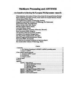
FPGA prototype system block diagram.
transfers can be acknowledged. Explicit acknowledgments can be accumulated in counters for completion notifications of one or more multiword transfers, even over an unordered network. Figure 3 shows how acknowledgments are generated for each NoC packet. Three types of lines inside a scratchpad region are depicted in the middle, with read and write request packets arriving from the left, and the corresponding generated reply packets on the right. A read packet arriving to normal scratchpad memory generates write reply packets according to the destination and acknowledgment addresses in the read (this is also true for counters –not shown). When a read arrives at a queue, the write reply may be delayed. Writes arriving at any type of line generate acknowledgments toward the acknowledgment address in the write and the size of the write packet as the data. This size can be accumulated in counters for completion notification of the initial transfer request (read or write). Acknowledgments arriving at any type of line act as writes (not shown), but do not generate further acknowledgments. IV. H ARDWARE P LATFORM The proposed architecture described in section 3, has been fully implemented in a hardware prototype based on Xilinx Virtex-5 FPGA. The detailed performance evaluation of the FPGA platform for simple remote store/loads and RDMA was presented in [12][13]. The block diagram of the FPGA system is presented in figure 4. There are four Xilinx Microblaze IP cores, each with 4KB L1 instruction and data caches and a 64KB L2 data cache where our network interface mechanisms are integrated. An on-chip crossbar connects the 4 processors through their L2 caches and NI’s, and the DRAM controller, and the interface (L2 NI) to a second-level, 3-plane 16 × 16 interconnect, that can be used to scale the system up to a 64-processor system. V. P ERFORMANCE E VALUATION This section presents the performance evaluation of the proposed system in the domain of network processing ap-
The setup for the performance evaluation of the system is the following. One processor is used to generate packets and to receive the processed packet. This processor generates the packets and stores them to a multiple reader Queue (mr-Q). In network processing platforms there are two commonly used configuration to connect the cores; pipelined or pooled. In the pipeline case, each stage is configured for a specific processing of a packet. For example, the first stage performs the IP lookup, the second stage the header processing and the third stage the payload processing. The main drawback in this case is that each stage should be carefully implemented in order to have a balanced pipeline. Otherwise, some processors will stay idle waiting for the processors of the earlier stages. In the pool configuration, packets are stored in a specific queue and each processors is request a packet from the queue after the processing it is forwarded to another queue. This approach has been selected for the performance evaluation since it can achieve higher parallelism. B. Header processing Figure 5(a) shows the execution time to process 1K packets in the case of fragmentation for several packet sizes using 1, 2, or 3 processors (the maximum fragmented packet has been set to 64 bytes; e.g. in a packet with packet size 128 bytes, two iteration of the fragment function is performed). In this case, the first processor generates the packets and stores them in a mr-Q, located in its local scratchpad. This processor uses a local counter for congestion management using credits. Every time a packet is generated, 20 bytes are reduced from the counter until the buffer is full. The other processors send request messages (of 20 bytes) as it was explained in section III-C. After the message (header) has been transfered to the processor, an acknowledgment is generated as was described in section III-D and is sent to the remote counter which atomically increase itself by 20 bytes. Hence, using the supported hardware primitives we can achieve high programming efficiency in the domain of network processing applications. As shown in this figure, the speedup is proportional to the number of cores. In general, network processing application are inherently parallel, therefore the main barrier to achieve high speedup is the communication overhead. Figure 6
Execution time for FRAG 1
2
FRAG�Execution�time�breakdown Comp
3 Normalized�execution�time malized�execution�time cution�time me
8000 7000
cc (x10E3)
6000 5000 4000
3000 2000 1000
Comm
100% 90% 80% 70% 60% 50% 40% 30% 20% 10% 0%
0 64
128
256
512
1024
Packet�size�Ͳ Cores
Packet size
Figure 6.
(a) Execution time for FRAG
˜ takes 52.000 cc, while the time to transfer 64 bytes using RDMA is around 52 cc.
Execution�time�for�CAST 1
2
3
900
D. Shared vs distributed queues
800
cc�(x10E6))
700 600 500 400 300 200 100 0 64
128
256
512
1024
P k t i Packet�size
(b) Execution time for CAST Figure 5.
Execution time breakdown for FRAGMENT
Execution time for Header and Payload processing
shows the breakdown of the execution time. When the packet size is small (e.g 64 or 128 bytes) the communication overhead is 12%-20% of the total execution time. When the packet size is larger, the communication overhead is less than 8% of the total execution time. C. Payload processing Figure 5(b) shows the execution time to process 1K packets using the CAST algorithm for several packet sizes using 1, 2, or 3 processors. In this case, the RDMA mechanisms are used, to transfer the payload of the packets to the processors. One processor is used to generate the packets and distributes them in a round-robin way using RDMAs. A specific location per processor in the local scratchpad is used to signal whether each processor is idle or not. After the processing of the packet, each processor asserts this remote location (by sending a message) to signal that it is idle. The speedup of the system is again proportional to the number of cores used for the processing. This application is computational bounded since the encryption of 64 bytes
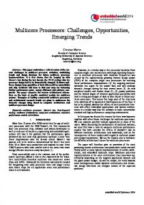
In many network processing application a hybrid architecture is used in which several processors (pool) are used in every stage of a pipeline (e.g. a small number of processors are used in the stage of IP lookup, while a larger number is used for the payload processing). To evaluate the system under this configuration, we consider two cases for interprocess communication. In the first case, all processors of the first stage send the packets in a shared mr-Q. The processors of the second stage send requests to this shared queue to receive the packets for processing. In the second case, each processor of the first stage stores the packets in a single reader queue in its local scratch pad. The processors of the second stage have to poll the distributed queues in a round-robin scheme to request the packets. Figure 7(b) shows the execution time for both cases. As shown in the figure, the shared queue perform slightly better (up to 11%) than the distributed queues. On the other hand, using a shared queue results to higher communication traffic, since the packets have first to travel to the shared queue and then to the second stage (thus the shared queue results in higher power consumption). VI. C ONCLUSIONS In this paper a multi-core FPGA platform has been evaluated in the domain of the network processing, that merges efficiently the cache, the scratchpad and the network interface. Two representative application are evaluated using the proposed scheme– header and payload processing, using remote load/stores and RDMA respectively. Finally, the system is evaluated for hybrid architectures (pipeline of pool) in which several processors have to communicate using either shared or distributed queues. As it was shown, the hardware primitives (counters, queues, notification) for the communication and the synchronization of the processors
SHARED QUEUE Source Processor
M wr
Source Processor
wr M
M
chip multiprocessors, SIGARCH Comput. Archit. News, v.35, (2007)
Destination Processor
[2] Wolf, T., Franklin, M.: CommBench - A Telecommunications Benchmark for Network Processors. Proc. of IEEE International Symposium on Performance Analysis of Systems and Software (ISPASS), Austix, TX, 154–162 (2000)
rd
rd
M
Destination Processor
[3] SARC: Scalable computer ARChitecture. European IP Project, 2005-2009, http://www.sarc-ip.org
DISTRIBUTED QUEUE Source Processor
Source Processor
wr M
wr M
rd
rd
M
M
[4] Mai, K. and Paaske, T. and Jayasena, N. and Ho, R. and Dally, W.J. and Horowitz, M: Smart Memories: a Modular Reconfigurable Architecture. Proc. of the 27th International Symposium on Computer Architecture (ISCA), 2000
Destination Processor
[5] Sankaralingam, K. and Nagarajan, R. and Mcdonald, R. and Desikan, R. and Drolia, S. and Govindan, M.S. and Gratz, P. and Gulati, D. and Hanson, H. and Changkyu Kim and Liu, H. and Ranganathan, N. and Sethumadhavan, S. and Sharif, S. and Shivakumar, P. and Keckler, S.W. and Burger, D.: Distributed Microarchitectural Protocols in the TRIPS Prototype Processor, Proc. of the 39th IEEE/ACM International Symposium on Microarchitecture (MICRO),2006
Destination Processor
(a) Configuration
Shared
Distributed
8000
[6] J. Kubiatowicz and A. Agarwal: Anatomy of a Message in the Alewife Multiprocessor, Proc. of the 7th ACM International Conference on Supercomputing (ICS), 1993, Tokyo, Japan
7000
cc (xE3)
6000 [7] J. Heinlein and K. Gharachorloo and S. Dresser and A. Gupta: Integration of Message Passing and Shared Memory in the Stanford FLASH Multiprocessor, ACM SIGOPS Oper. Syst. Rev., v.28, no.5,1994, pp.38–50
5000 4000
3000 2000
[8] S. Mukherjee and B. Falsafi and M.D. Hill and D.A. Wood: Coherent Network Interfaces for Fine-Grain Communication, Proc. of the 23rd International Symposium on Computer Architecture (ISCA), 1996
1000
0 64
128
256
512
1024
Packet Size (b) Execution time Figure 7.
Shared vs Distributed queues
are most suitable for network processing applications and improve significantly the programming efficiency. Furthermore, the merged cache with the scratchpad and the virtualized network interface provides low latency for interprocess communication which is crucial in the domain of network processing. Finally, the evaluation shows that the common shared queue achieves lower latency although it increases the communication traffic (in contrast to the distributed queues). ACKNOWLEDGMENT This work was supported by the European Commission in the context of the projects FP6 IP SARC and HiPEAC NoE. R EFERENCES [1] J.Leverich, H. Arakida, A. Solomatnikov, A. Firoozshahian, M. Horowitz, C. Kozyrakis: Comparing memory systems for
[9] G.T. Byrd and B. Delagi: Streamline: Cache-Based Message Passing in Scalable Multiprocessors. Proc. of the 20th International Conference on Parallel Processing (ICPP), 1991 [10] Byrd, G.T. Flynn, M.J.: Producer-Consumer Communication in Distributed Shared Memory Multiprocessors, Proc. of the IEEE, v.87, no.3, pp.456–466, Mar,1999 [11] R.A.F. Bhoedjang and T. Ruhl and H.E. Bal: User-Level Network Interface Protocols, IEEE Computer, v.31, no. 11, pp.53–60, (1998) [12] Kalokerinos, G., Papaefstathiou, V., Nikiforos, G., Kavadias, S.,Katevenis, M., Pnevmatikatos, D., Yang X: FPGA implementation of a configurable cache/scratchpad memory with virtualized user-level RDAM capability Proc. of IEEE International Conference on Embedded Systems: Architectures, Modeling and Simulation (SAMOS 2009), pp. 149–156, July 2009 [13] Kavadias, S.,Katevenis, M., Zampetakis M., Nikolopoulos, D.: On-Chip Communication and Synchronization Mechanisms with Cache-Integrated Network Interfaces. Proc. of IEEE International Conference on Computing Frontiers, May 2010