SIViP DOI 10.1007/s11760-009-0111-x
ORIGINAL PAPER
New adaptive complex IIR filters and their application in OFDM systems Zlatka Nikolova · Vladimir Poulkov · Georgi Iliev · Karen Egiazarian
Received: 12 September 2008 / Revised: 31 January 2009 / Accepted: 1 February 2009 © Springer-Verlag London Limited 2009
Abstract In this article, very low sensitivity variable complex filter (VCF) sections are developed. They have two important advantages: extremely low passband sensitivity and independent tuning of the bandwidth and the central frequency over a wide frequency range. The first advantage provides resistance to quantization effects, while the second one gives a better digital signal processing quality and extends the area of possible applications of the developed filters. Based on the proposed VCF sections an adaptive complex system is designed which demonstrates very fast convergence and low computational complexity. This system is applied for narrowband interference cancellation in multiband orthogonal frequency division multiplexing receivers and wideband noise cancellation in OFDM receivers. It is experimentally verified that a better signal-to-noise ratio and signal-to-interference ratio can be achieved using the proposed adaptive complex filtering scheme. Keywords Complex digital IIR filters · Adaptive complex filtering · Narrowband interference · OFDM systems
Z. Nikolova (B) · V. Poulkov · G. Iliev Department of Communication Networks, Faculty of Telecommunications, Technical University of Sofia, 8 Kliment Ohridski, 1000 Sofia, Bulgaria e-mail:
[email protected] V. Poulkov e-mail:
[email protected] G. Iliev e-mail:
[email protected] K. Egiazarian Department of Signal Processing, Tampere University of Technology, P.O. Box 527, 33101 Tampere, Finland e-mail:
[email protected]
1 Introduction The issue of interference/noise avoidance, suppression or cancellation is of primary importance for many telecommunication applications and has been studied extensively in the recent years. Wideband wireless communication systems are very sensitive to narrowband interference (NBI), which can even block the system performance [1]. NBI suppression in quadrature phase shift keying (QPSK) spread-spectrum communication systems is discussed in [2]. Discrete multi-tone (DMT) modulation systems, such as DMT VDSL, are very sensitive to radio frequency interference (RFI) and RFI suppression has been discussed in many works, such as [3–5]. Reference [6] studies algorithms for the RFI cancellation in VDSL systems. Besides DMT modulation, the orthogonal frequency division multiplexing (OFDM) is other leading technology for many broadband communication systems, such as MB-OFDM ultra wideband systems. Because of NBI, signal-to-interference ratio (SIR) dropping can seriously degrade the characteristics of these systems [7]. The problem of detection, tracking and suppression/elimination of harmonic and narrowband signals mixed with broadband noise have been discussed in a number of publications. In [8], a parameter estimation of chirp signals embedded in noise is made. Related problems are discussed in [9] with respect to CDMA and TDMA systems. The problem of interference is encountered in various kinds of broadband telecommunication systems, but the methods for interference suppression proposed so far can be generalized into two approaches. The first approach concerns various frequency excision methods, while the second relates to so-called cancellation techniques. These techniques aim to eliminate or reduce interference in the received signal by the use of adaptive notch filtering-based methods or NBI identification [10].
123
SIViP
This article addresses adaptive notch filtering as a method for wideband noise cancellation associated with analytic signals, as well as NBI suppression in ultra wideband signals. An adaptive complex system based on very low sensitivity (LS) variable complex filter (VCF) sections is developed. The behaviour of the VCF after coefficient quantization in a very short word-length is experimentally investigated, together with their low coefficient sensitivities, since they significantly improve the quality of the adaptive filtering process. The narrowband adaptive complex filter (ACF) is tested with different values of the main filter parameters, such as step of adaptation, filter bandwidth (BW) and central frequency disposition. It is shown that the proposed ACF scheme successfully cancels NBI, thereby significantly decreasing the SIR. The adaptive complex system is suggested to be used in an OFDM transmission scheme for wideband noise cancellation. The concept is based on the realization of a low intermediate frequency (IF) quadrature receiver similar to the one suggested in [11]. The article is organized as follows: In Sect. 2, recursive (IIR) digital VCF are derived and investigated to determine their sensitivity and tuning capabilities. The adaptive complex narrowband system is designed in Sect. 3. Its ability to eliminate narrowband complex signals is demonstrated. The application of the proposed adaptive complex filtering scheme in OFDM systems for noise/interference cancellation is discussed in Sect. 4. Finally, Sect. 5 concludes the article.
and Watanabe (MNW-method) [14]. Despite showing the undoubted capabilities, these methods also have some disadvantages, which should not be ignored. The most significant of them could be summarized as follows: the likelihood of producing delay-free loops. The MNR-method partly avoids the problem but, in consequence, the tuning of the BW without degradation of the magnitude characteristics is possible only over a very limited frequency range. Certain frequency restrictions have to be applied to these methods: either one of the cut-off frequencies, or one of the passband edges, must remain fixed. The stopband sensitivity is high enough to cause additional deterioration of the frequency characteristics. Only classical approximations are applicable and moreover only even-order transfer functions can be achieved. The derived variable structure usually employs too many elements. The simultaneous and independent tuning of the BW and central frequency is limited. The method for design of VCF, proposed in [12], avoids the above-described drawbacks. Very narrowband bandpass (BP)/bandstop (BS) first- and second-order filter sections with complex coefficients can be designed by means of this method. It can be summarized in a few steps but before defining them, it is necessary to introduce some preliminary considerations. If the variable z in a given real lowpass (LP)/highpass (HP) LP/HP digital transfer function HReal is substituted by LP/HP
HReal
z =1 = z −1 (cos θ+ j sin θ)
BP/BS
(z) −−−−−−−−−−−−−−→ HComplex (z)
(1)
BP/BS
2 Efficient digital VCF The quality of adaptive filtering depends on two major factors—the convergence and efficiency of the adaptive algorithm, and the capacities of the adaptive structure. In most adaptive filtering research studies, the adaptive filter realizations and their properties are usually overlooked, whereas a lot has been done to improve the adaptive algorithms. Below efficient ACF sections are proposed and the influence of their properties on the adaptive process is shown experimentally. Attention is focused on first-and secondorder VCF sections, as they are able to set up cascade structures of any order. They are designed in accordance with the method for variable complex IIR filters derivation, as proposed in [12].
the new transfer function HComplex (z) will be of BP/BS type and will have complex coefficients and central frequency everywhere on the frequency axis (0 − π ). A transfer function with complex coefficients could be easily decomposed into its real and imaginary parts: BP/BS
HComplex (z) = HRe (z) + j HIm (z)
(2)
and the corresponding complex circuit can be either directly synthesized or obtained through a circuit transformation [15]. It always has two inputs and two outputs, both couples real and imaginary (Fig. 1). Four possible transfer functions are realized, two by two equal and fit together with the real and imaginary parts of the complex transfer function (Eq. 2) as follows HRe (z) = HRR (z) = HII (z) HIm (z) = HRI (z) = −HIR (z)
(3)
2.1 Variable complex IIR digital filters design procedure In addition to a detailed investigation of the derivation of real variable filters, a number of methods for the design of complex coefficient variable filters are developed. The two most popular are the Mitra, Neuvo and Roivainen method (MNRmethod) [13], and the one proposed by Murakoshi, Nishihara
123
Re Input
Im Input
+
HRe(z) HIm(z)
+
Re Output Im Output
Fig. 1 Block-diagram of a complex coefficients digital filter
SIViP β
f
z-1 bˆ
b
In
+
+ +
b
+
Out LP
+
Out HP
(a)
Fig. 2 The structure of a composite multiplier 0,5
In
If the initial real function is of LP type and N -order, then all transfer functions (Eq. 3) are of BP type and of 2N -order. If it is of HP type, then HRR (z) = HII (z) change to a BS type. The functions (Eq. 3) are real coefficients transfer functions. In order to realize BP/BS VCF with central frequency tuned by changing of θ the complex transformation (Eq. 1) is applied. The BW of the complex filter is tuned by β introduced with the LP to LP spectral transformation of Constantinides z −1 →
z −1 − β = T (z) 1 − βz −1
(4)
followed by truncated Taylor series expansion in order to avoid delay-free loops. Thus, the transfer function of a BWvariable filter is obtained. The corresponding variable structure consists so called composite multipliers (Fig. 2). Therefore, the proposed method for the development of BP/BS variable complex filters can be encapsulated in the following steps 1. Shift the desired BP or BS magnitude arithmetically symmetric specifications along the frequency axes until the zero frequency coincides with the central frequency of the specifications, thus turning them to LP or HP type. 2. Apply any possible LP or HP approximation. Then, decompose the transfer function into second-order and possibly one first-order terms and design the corresponding LP first- and second-order real filter sections. 3. In order to make the filter sections BW-variable, apply the Constantinides LP—LP transformation ( Eq. 4), expand the coefficients functions of β into Taylor series and truncate to the linear terms only. The real multipliers are replaced with the composite multipliers (Fig. 2) containing parameter β to trim the BW. 4. Using the complex conversion (Eq. 1) or the corresponding circuit transformation [15] the central frequencyvariable real complex coefficient first- and second-order sections are obtained. The central frequency of the filters can be tuned independently, and without limitation, by changing the value of θ. The proposed method for the design of IIR digital VCF has the following principal advantages: • The designed complex digital structures are with canonical numbers of elements. • Delay-free-loops are avoided after the method is applied.
+
a
b
+ z
-1
+ +
+
+
+
z -1 +
Out HP
Out LP
(b) Fig. 3 Real coefficients LP/HP filter sections. a First-order (LS1b), b second-order (LS2)
• The central frequency and BW are tuned independently and very accurately over a wide frequency range. Very narrowband BP/BS filters can be developed. • Higher freedom of tuning, reduced complexity and lower stopband sensitivity compared to the two most often used methods are achieved. • It is possible to use any classical or more general approximation producing transfer function of arbitrary order (odd or even). The described method is applicable to the design of BP/BS IIR variable complex first- and second-order narrowband filter sections, as set out in Sect. 2.2 below. 2.2 First- and second-order VCF sections derivation The proper selection of real prototype circuits is of key importance in achieving the desired properties of the developed variable complex filters. Two universal (LP/HP) real sections are selected. The firstorder section (Fig. 3a), named LS1b and proposed in [16] realizes transfer functions (Eq. 5). The second-order section LS2 [17] (Fig. 3b) is also universal, realizing LP and HP transfer functions, respectively (Eqs. 6, 7). LP = HLS1b
b(1+z −1 ) ; 1−(1−2b)z −1
HP HLS1b =
(1−b)(1−z −1 ) 1−(1−2b)z −1
(5)
LP = 0, 5 HLS2
a(1 + z −1 )2 1 + (−2 + 2a + b)z −1 + (1 − b)z −2
(6)
HP HLS2 = 0, 5
(2 − a − b)(1 − z −1 )2 1 + (−2 + 2a + b)z −1 + (1 − b)z −2
(7)
Both structures in Fig. 3 are canonical realizations with respect to the number of elements and demonstrate very low coefficient sensitivity, especially for the most significant cases in practice of narrowband LP and wideband HP
123
SIViP
Out Im2 Out Im1 In Re
+ bˆ
cos θ
+
+
sin θ
sin θ
+
cos θ
In Im
+
= 0, 5aˆ
Out Re1 Out Re2
(a) In Re
bˆ
+
+
â
Out Re1
+
+
+ +
+
+
z-1
z-1
+
+
+
z-1
BS BS HRR2 = HII2 =
+
cos θ
+
Out Im2 bˆ
â +
0,5
+
+
Out Im1
+
Fig. 4 Complex coefficient second-order BP/BS filter sections. a LS1b, b LS2
filtering. The sections are limit-cycle-free realizations and, after applying the above described design procedure, efficient variable complex BP/BS filters are derived (Fig. 4a, b). As the initial structures are universal, having one-input and two-outputs (LP and HP), the developed variable complex BP/BS filters will also be universal, realizing two inputs (real and imaginary) and four outputs (two real-imaginary couples—one LP-based and the other one HP-based real prototype). Therefore, each variable complex structure is able to realize eight transfer functions two by two equal in accordance with Eq. 3. For the LS1b complex filter section they are as follows −2 ˆ 1+2bˆ Az −1 +(2b−1)z BP BP = HII1 = bˆ HRR1 1+2(2bˆ − 1)Az −1 + (2bˆ − 1)2 z −2
2B1 C z −1 1 + 2(2bˆ − 1)Az −1 + (2bˆ − 1)2 z −2
BS BS = HII2 = B1 HRR2
ˆ −2 1−2B1 Az −1 +(1 − 2b)z −1 + (2b−1) 2 z −2 ˆ ˆ 1+2(2b−1)Az
(8)
(9)
(10)
(13)
ˆ 1+[(B2 −2)A]z −1 +[(1+B1 ) (2−a− ˆ b) 2 1+2B2 Az −1
−3 +B z −4 ˆ (A2 −C 2 )−2B2 ]z −2 +[(2a+3 ˆ b−4)A]z 1 (14) 2 2 2 2 −2 −3 +[B2 +2B1 (A −C )]z +2B1 B2 Az +B1 z −4 BP P HRI2 = −H IBR2 =
(b)
BP BP HRI1 = HIR1 = bˆ
−(B2 − 2)C z −1 1 + 2B2 Az −1
+[B22 +2B1 (A2 −C 2 )]z −2 +2B1 B2 Az −3 + B12 z −4
sin θ
sin θ
BP BP = −HIR1 = 0, 5aˆ HRI1
ˆ +2bˆ AC z −2 +(2aˆ +3b−4)C z −3
+
cos θ
+
Out Re2 cos θ
z-1
sin θ
sin θ
123
1 + [(B2 + 2)A]z −1 + [2B2 + (1 + B1 ) 1 + 2B2 Az −1
+[B22 +
In Im
(11)
−3 + B z −4 ˆ (A2 −C 2 )]z −2 + [(2aˆ − b)A]z 1 (12) + 2B1 (A2 −C 2 )]z −2 +2B1 B2 Az −3 + B12 z −4
0,5
cos θ
−1 +(2b−1) 2 z −2 ˆ ˆ 1+2(2b−1)Az
BP BP HRR1 = HII1
bˆ
z-1
+
ˆ z −1 −2bC
The LS2 variable complex structure realizes the transfer functions ( Eqs. 12–15)
+ +
+
+
z-1
BP BP = HIR2 = B1 HRI2
ˆ −(B2 + 2)C z −1 (2 − aˆ − b) 2 1 + 2B2 Az −1
ˆ z −3 +2bˆ AC z −2 +(2aˆ − b)C (15) +[B22 + 2B1 (A2 −C 2 )]z −2 +2B1 B2 Az −3 + B12 z −4 In Eqs. 8–15, bˆ denotes the composite multiplier and B1 = ˆ A = cos θ, C = sin θ and B2 = 2â + bˆ − 2. 1 − b, A real LP prototype filter section produces transfer functions (Eqs. 8, 9, 12, 13) all of BP type. If the prototype is of HP type the realized complex transfer functions are of both types BP (Eqs. 11, 15) and BS (Eqs. 10, 14). All transfer functions have variable BW (by changing β) and central frequency (by changing θ ). 2.3 Sensitivity investigations and tuning abilities Experimental results in respect of worst-case sensitivity of magnitude responses, coefficients quantization with different word-length and the BW and central frequency tuning of the LS1b and LS2 VCF will be presented here. As all eight transfer functions of the variable first- and second-order complex sections demonstrate similar results, only those for Eqs. 8 and 12 will be given. In order to illustrate the reduction in sensitivity, some results for the worst-case sensitivities for both complex LS1b and LS2 filters are compared with other popular structures.
SIViP
Fig. 5 Worst-case sensitivity of narrowband BP complex. a MHNS and LS1b, b DF, MN and LS2 filter sections
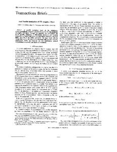
The best competitor to our LS1b section is the so-called MHNS filter. The worst-case sensitivity magnitude responses for the narrowband complex digital LS1b and MHNS filters are given in Fig. 5a. It is obvious that the sensitivity of the LS1b complex section is hundreds of times lower than that of the MHNS complex section [18]. In Fig. 5b, the worst-case sensitivity of the complex LS2 filter is compared to two other well-known second-order complex structures: the direct-form (DF) and the minimumnorm-based (MN) for the same pole position near the unit cycle providing narrowband realization. It is evident that the LS2 filter exhibits approximately 10 times lower worst-case sensitivity compared to the MN-based, and about 50 times lower than DF-based. In addition, the LS2 section worst-case sensitivity is a smooth curve. The rivals’ worst-case sensitivities are visibly uneven and vary within a large interval of values, making the filters applicable only in a few narrowband frequency areas where the sensitivity is reasonably low.
Fig. 6 Magnitude responses of variable complex BP. a LS1b and b LS2 filter sections for different word length
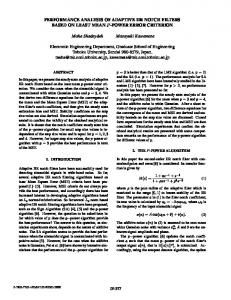
The lower coefficient sensitivity ensures higher accuracy of the tuning process, thus permitting shorter multiplier coefficient word-length for a desired accuracy. As a result, computations and updating of the tunable filter coefficients become faster. Due to the very low coefficient sensitivity of the initial sections, the LS1b (Fig. 6a) and LS2 (Fig. 6b) VCF sections behave very well even when the coefficients are quantized to a very short word-length without excessively affecting the filter characteristics [18]. In Fig. 7a, it is shown how the central frequency of the narrowband LS1b section is tuned by trimming of θ, while the BW tuning by changing of β is shown in Fig. 7b [19]. The corresponding graphics for the transfer function (Eq. 12) of LS2 VCF are shown in Fig. 8a for the central frequency and in Fig. 8b for the BW tuning, respectively. It is seen that for both LS filters, the BW is tuned without a problem over a wide frequency range and the shape of the magnitude is not degraded throughout the tuning process.
123
SIViP
(a) 100
θ=π/10
-1
θ=π/2
θ=3π/10
θ=7π/10
θ=9π/10
MAGNITUDE
10
-2
10
-3
10
0
0.1
0.2
0.3
0.4
0.5
0.6
0.7
0.8
0.9
1
NORMALIZED FREQUENCY
(b)
Fig. 7 Magnitude responses of variable BP complex LS1b filter for different values of a θ and b β
Fig. 8 Magnitude responses of variable BP complex LS2 filter for different values of a θ and b β ADAPTIVE ALGORITHM
3 Adaptive complex system
+
xR(n)
3.1 Development of the adaptive complex system
xI(n)
In Fig. 9, a block-diagram of a BP/BS adaptive complex system is shown. The variable LS filter sections from Sect. 2 are used and the least mean squares (LMS) algorithm is applied to adapt the central frequency. Furthermore, only the input/output relations for the BP/BS variable complex LS1b filters only are considered [19]. The adaptive process for the LS2 filters can be mathematically described by analogy [20]. For the BP LS1b filter we have the following real output
eR(n) yR(n
VARIABLE COMPLEX FILTER
yI(n) +
eI(n)
ADAPTIVE COMPLEX SYSTEM Fig. 9 Block-diagram of a BP/BS adaptive complex system
where y R1 (n)
= −2(2β − 1) cos θ (n)y R1 (n − 1) −(2β − 1)2 y R1 (n − 2) + 2βx R (n) + 4β 2 cos θ (n)x R (n − 1)
y R (n) = y R1 (n) + y R2 (n)
123
(16)
+ 2β(2β − 1)x R (n − 2)
(17)
SIViP
y R2 (n) = − 2(2β − 1) cos θ (n)y R2 (n − 1) − (2β − 1) y R2 (n − 2) 2
− 4β(1 − β) sin θ (n)x I (n − 1)
(18)
The imaginary BP output is given by the following equation y I (n) = y I 1 (n) + y I 2 (n)
(19)
where y I 1 (n) = −2(2β − 1) cos θ (n)y I 1 (n − 1) − (2β − 1)2 y I 1 (n − 2) + 4β(1 − β) sin θ (n)x R (n − 1)
In order to ensure the stability of the adaptive algorithm the range of the step size µ is set in accordance with the results reported in [15] 0 0.
123
SIViP
DSP module
I A/D RF
Q
LPF
IIR Adaptive Complex Filter
FFT LPF
A/D
IF control
D E M A P
IF Generator
Fig. 15 OFDM receiver with noise cancellation
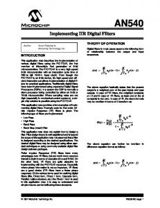
4.2 Noise cancellation in OFDM receivers The idea of an OFDM system for noise cancellation using a narrowband ACF for such wireless applications is depicted in Fig. 15 [20]. The signal from the antenna, after filtering and amplification by a LNA in the RF module, is demodulated in two channels—inphase and quadrature. They correspond to the real and complex parts of the signal from the IFFT at the transmitter and after ADC are fed to the inputs of the narrowband ACF for noise cancellation. Conversion to baseband is performed by IF demodulation and LPF. The complex multicarrier baseband signal is fed to the FFT circuit and after demapping is demodulated to n-QAM and binary form. A control IF signal from the filter is utilize to avoid any frequency mismatch of the IF frequency in the demodulation process. This control signal is a function of the coefficient θ responsible for the central frequency of the filter. As seen from Fig. 15, all signal operations after the RF module are performed digitally and could be implemented in one digital signal processing (DSP) circuit. A simulation model of the OFDM system was developed to evaluate the bit error rate (BER) as a function of the signal-to-noise ratio (SNR). For the purpose of comparison, the estimations of the BER/SNR curves were conducted relative to baseband in the cases with and without adaptive filtering. The results in Fig. 16 show that for low SNR a gain of up to 10 dB could be obtained for the scheme proposed in Fig. 15.
Fig. 16 BER versus SNR
the entire frequency band. The precision of tuning is very high and it is possible to use coefficients with shorter word length, thus decreasing the power consumption for adaptive filtering as well as for the coefficient-updating. The convergence of the adaptive algorithm for the developed VCF is investigated experimentally and the efficiency of the adaptation is unquestionably proven. Two applications of the ACF in OFDM systems are presented—for NBI in MB-OFDM systems and for noise cancellation in OFDM receivers. In both applications, one and the same narrowband ACF is used. Concerning the NBI cancellation one advantage is that the adaptive complex system is universal -realizing BP and BS outputs simultaneously. As well as being suppressed, the NBI can be also monitored and the ACF can be deactivated at the point where the interference vanishes or is reduced to an acceptable level. Experiments demonstrate that in both applications the performance of the OFDM systems is improved. Acknowledgments This work was supported by the Bulgarian National Science Fund–Grant No. 01-109/2008.
References 5 Conclusions In this article, an improved method of design of very low sensitivity variable complex BP/BS filter sections with accurate and completely independent tuning of the BW and central frequency is presented. The method permits the BW to be tuned in a much wider frequency range compared to other well-known methods and without any frequency limitations imposed by the design procedure restrictions. The transformation factor θ adaptively tunes the central frequency over
123
1. Giorgetti, A., Chiani, M., Win, M.Z.: The effect of narrowband interference on wideband wireless communication systems. IEEE Trans. Commun. 53(12), 2139–2149 (2005) 2. Jiang, H., Nishimura, S., Hinamoto, T.: Steady-state analysis of complex adaptive IIR notch filter and its application to QPSK communication systems. IEICE Trans. Fundam. E85-A(5), 1088– 1095 (2002) 3. Rauschmayer, D.: ADSL/VDSL Principles. Macmillan, New York (1999) 4. Starr, T., Cioffi, J., Silverman, P.: Understanding Digital Subscriber Line Technology. Prentice-Hall, Englewood Cliffs (1999) 5. Starr, T., Sorbara, M., Cioffi, J., Silverman, P.: DSL Advances. Prentice-Hall, Englewood Cliffs (2003)
SIViP 6. Yaohui, L., Laakso, T.I., Diniz, P.S.R.: Adaptive RFI cancellation in VDSL systems. ECCTD’01- European Conference on Circuit Theory and Design, Espoo, Finland, 28–31 August 2001 7. Carlemalm, C., Poor, H.V., Logothetis, A.: Suppression of multiple narrowband interferers in a spread-spectrum communication system. IEEE J. Select. Areas Commun. 3(5), 1431–1436 (2004) 8. Pei, S.C., Tseng, C.C.: Complex adaptive IIR notch filter algorithm and its applications. IEEE Trans. Circuits Syst. II 41(10), 158– 163 (1994) 9. Hara, S., Matsuda, T., Ishikura, K., Morinaga, N.: Coexistence problem of TDMA and DS-CDMA systems-application of complex multirate filter bank. In: Proceedings of GLOBECOM’96 Communications, The Key to Global Prosperity, vol. 2, pp. 1281– 1285, London (1996) 10. Baccareli, E., Baggi, M., Tagilione, L.: A novel approach to inband interference mitigation in ultra wide band radio systems. IEEE Conference on Ultra Wide Band Systems and Technologies (2002) 11. Dias, V.: Complex signal sigma-delta modulators for quadrature bandpass A/D conversion. Microelectron. J. 27, 505–524 (1996) 12. Stoyanov, G., Nikolova, Z.: Improved Method Of Design Of Complex Coefficients Variable Iir Digital Filters, vol. 2, pp. 40–46. TELECOM’99, Varna (1999) 13. Mitra, S.K., Neuvo, Y., Roivainen, H.: Design of recursive digital filters with variable characteristics. Int. J. Circuit Theory Appl. 18, 107–119 (1990) 14. Murakoshi, N., Nishihara, A., Watanabe, E.: Synthesis of variable filters with complex coefficients. Electron. Commun. Japan, Part 3. 77(5), 46–57 (1994) 15. Watanabe, E., Nishihara, A.: A Synthesis of a class of complex digital filters based on circuitry transformations. IEICE Trans. E-74(11), 3622–3624 (1991)
16. Topalov, I., Stoyanov, G.: Low-sensitivity first-order digital filter sections without limit cycles. Electron. Lett. 26, 25–26 (1990) 17. Topalov, I., Stoyanov, G.: A systematic approach to the design of low-sensitivity limit-cycle-free universal bilinear and biquadratic digital filter sections. In: Proceedings of 10th European Conference on Circuit Theory and Design, vol.1, pp. 213–222, Copenhagen (1989) 18. Stoyanov, G., Kawamata, M., Valkova, Z.: New first and secondorder very low-sensitivity bandpass/ bandstop complex digital filter sections. In: Proceedings of IEEE 1997 Region 10th Annual Conference “TENCON’97”, vol. 1, pp. 61–64, Brisbane, 2–4 December 1997 19. Iliev, G., Nikolova, Z., Stoyanov, G., Egiazarian, K.: Efficient design of adaptive complex narrowband IIR filters. In: Proceedings of XII European Signal Processing Conference, EUSIPCO 2004, pp. 1597–1600, Vienna, 6–10 September 2004 20. Iliev, G, Nikolova, Z., Poulkov, V., Stoyanov, G.: Noise cancellation in OFDM systems using adaptive complex narrowband IIR filtering. IEEE International Conference on Communications (ICC-2006), pp. 2859- 2863, Istanbul, Turkey, 11–15 June 2006 21. Nikolova, Z., Iliev, G., Stoyanov, G., Egiazarian, K.: Design of adaptive complex IIR notch filter bank for detection of multiple complex sinusoids. In: Proceedings of 2nd International Workshop on Spectral Methods and Multirate Signal Processing (SMMSP’2002), pp. 155–158, Toulouse, 7–8 September 2002 22. Nikolova, Z., Poulkov, V., Iliev, G., Stoyanov, G.: Narrowband interference cancellation in multiband OFDM systems. Third Cost 289 Workshop Enabling Technologies for B3G Systems, Aveiro, Portugal, 12–13 July 2006
123