audio coding continues to occur since further bitrate reduc- tion is desirable ... cluded Discrete Wavelet Transform (DWT) ltering meth- ods [2]-[5]. In [2] ..... bitrates using the a signal adaptive switched lter- bank", Proc. ... Acoustic Guitar. 64. 23.
NEW RESULTS IN LOW BITRATE AUDIO CODING USING A COMBINED HARMONIC-WAVELET REPRESENTATION Simon Boland Mohamed Deriche Signal Processing Research Centre School of Electrical and Electronic Systems Engineering Queensland University of Technology GPO Box 2434 Brisbane Qld 4001
ABSTRACT
In this paper, we propose a new combined harmonic-wavelet representation for audio where a harmonic analysis-synthesis scheme is used, rst, to approximate each audio frame as a sum of several sinusoids. Then, the di�erence between the original signal and the reconstructed harmonic signal is analyzed using a wavelet ltering scheme. After each step (harmonic analysis & wavelet ltering), parameters are quantized and encoded. Compared to previously proposed methods, our audio coder uses di�erent harmonic analysis-synthesis and wavelet ltering schemes. We use the Total Least Squares (TLS)-Prony algorithm for the harmonic analysis-scheme, and an M-band wavelet transform for analyzing the residual. Altogether, our proposed coder is capable of delivering excellent audio signal quality at encoder bitrates of 60-70 kb/s.
1. INTRODUCTION
Uncompressed audio signals are typically sampled at 44.1 kHz and encoded with 16 bits/sample PCM, resulting in the large bitrate of 705 kb/s per channel. So far, some sophisticated audio coding schemes, such as the ISO/IEC MPEG [1], have been successful in reducing this bitrate to approximately 64 kb/s per channel with near transparent coded signal quality. Ongoing research in low bitrate high quality audio coding continues to occur since further bitrate reduction is desirable for numerous applications. These include Digital Audio Broadcasting (DAB), ISDN, Internet audio, and HDTV, to mention a few. Among the previous schemes proposed, a number have included Discrete Wavelet Transform (DWT) ltering methods [2]-[5]. In [2], a Wavelet Packet Transform with Cascaded Conjugate Quadrature Filters (CCQF) was investigated. This lter bank contains frequency divisions approximating the critical bands, however, large sidelobes are present in the frequency response of the subband lters. In general, most lter bank designs based on cascade schemes have poor channel separation. Thus compared to traditional ltering schemes such as the Modi ed Discrete Cosine Transform (MDCT), audio compression methods based solely on CCQF perform poorly at low bitrates for tonal-like audio signals, e.g. violin and clarinet [4]. 0 This work is supported by grants from the Australian Telecommunications and Electronics Research Board (ATERB) and the ARC small grant scheme.
In contrast to the MDCT, the Wavelet Transform provides a nonuniform time resolution. In wavelet ltering, the impulse response of high frequency lters are short while low frequency lters have a long impulse response. Hence the high frequency energy of the signal is localized to a smaller portion of time. This is useful for preserving the \transient-like" segments in audio signals. In cases where this does not happen, quantization noise produced in the frequency domain is transferred to the time domain. This is referred to, in the time domain, as pre-echo noise [6], and is believed to become audible when the lter bank time resolution is much larger than the auditory pre-masking time of approximately a few milliseconds. Recently, two audio coding schemes which incorporate wavelet ltering into an overall audio coding scheme have been investigated [5], [4]. Although the two schemes are di�erent, the basic philosophy of each approach is to use a wavelet ltering technique for coding non-stationary segments or components. Included in each design is a separate or combined transform with superior frequency selectivity which is used for coding tonal-like segments or components. Thus the Wavelet Transform is mainly included for the purpose of limiting the spread of the high frequency pre-echo noise in the time domain. In this paper, we propose a low bitrate audio coding scheme similar to that investigated in [4]. Each audio signal is rstly expressed as a sum of several sinusoids. The di�erence or residual between the original signal and the reconstructed harmonic signal is analyzed using a wavelet ltering scheme. Here, we propose an alternative method to [4] for the harmonic analysis-synthesis and wavelet ltering scheme. In section 2, each scheme (harmonic & wavelet) is explained, while the quantization of the respective parameters is detailed in section 3. In section 4, audio coding results are presented, and from which conclusions are drawn in section 5.
2. COMBINED HARMONIC-WAVELET REPRESENTATION
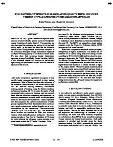
The overall block diagram of the proposed audio encoding and decoding scheme is illustrated in gure 1. The time signal is processed using frame sizes of 512 samples or 12 ms for 44.1 kHz sampled audio signals. A rectangular window is applied to each frame and no overlapping of frames is used here. The encoder starts by performing a harmonic analysis on the input signal frame, s, using the Total Least Squares (TLS)-Prony algorithm (described below). The outputs of
this algorithm are the frequencies, amplitudes and phases of the major harmonic components which are respectively denoted by fk , Ak and �k in gure 1. A masking model scheme based on the MPEG psychoacoustic model 2 implementation, [1], is then called. The tonality estimate of the masking model is ignored since information about the tonal and noise components of the input signal s is available from the harmonic analysis scheme. The frequencies, amplitudes and phases of the unmasked harmonics are then quantized and encoded, while the masked harmonic components are ignored. Side information about the number of harmonics must be sent to the decoder. The quantization techniques used here are described in section 3. A harmonic-like signal, h, is then reconstructed from the quantized parameters. This is subtracted from the input signal to give the residual signal, r. An M-band Discrete Wavelet Transform (DWT) described in section 4, is then used to decompose the residual signal into several subbands. In parallel with the DWT, a noise masking model is performed. The output of the noise masking threshold is used as input to a bit allocation algorithm which distributes bits to the DWT subbands. The bit allocation algorithm is similar to the MPEG bit allocation algorithm, [1]. The DWT subbands are then quantized using the number of bits determined from the bit allocation algorithm. The encoded DWT subbands and the bit allocation side information is sent to the encoded signal bitstream. The decoder then unpacks the encoded harmonic parameters, DWT subbands and the respective side information. The harmonic signal, h, is reconstructed from the quantized frequencies, amplitudes and phases of the harmonics. Likewise, an approximate residual signal, r^, is reconstructed from the inverse DWT. The two signals, h^ and r^ are summed to form the reconstructed time signal, s^.
2.1. TLS Prony Algorithm
Prony's method is a technique for modelling sampled data as a linear combination of exponentials. Given N complex data samples, x [1] ; :::; x [N ], expressed mathematically as, [7],
x^ [n] =
X A exp [(� + j2�f )(n p
k=1
k
k
k
1)T + j�k ]
(1)
where p is the number of complex exponentials in the model, T is the sample interval in seconds, Ak is the amplitude of the complex exponential, �k is the damping factor in seconds 1, fk is the sinusoidal frequency in Hz and �k is the sinusoidal initial phase in radians. For the case of real data samples the complex exponentials must occur in complex conjugate pairs of equal amplitude. For the proposed coder, an undamped sinusoidal model was selected for the harmonic representation, i.e. �k = 0; k = 1; :::; p=2. Thus for a given model order, p, the frequencies, amplitudes and phases need to be computed. For N = 2p, the original sequence x [n] can be represented exactly using a p-th model order as, [7],
x^ [n] =
Xh z p
k=1
k kn
1
(2)
where
hk = Ak exp(j�k ) zk = exp [(�k + j 2�fk )(n 1)T ]
However, in practice an overdetermined case exists where N > 2p and the data sequence can only be approximated. The solution of the overdetermined case is performed by constructing a set of Linear Prediction (LP) equations i.e.
X a [m] x [n p
m=1
where
X(z p
m=0
m] = e [n]
zk ) = �pk=1 (z zk )
(3) (4)
The am parameters can be estimated using an Least Squares (LS) algorithm. The frequencies, zk , can then be derived from the roots of the characteristic equation in equation (4). Then, a Vandermonde matrix of time-index z elements can be formed and used to solve for the unknown hk parameters using equation (2), and thus giving the amplitudes and phases of the complex sinusoids. This form of Prony's method degrades for signals containing large amounts of noise or for signals containing closely spaced sinusoids. A slightly di�erent method for solving the LP equations is to use the Total Least Squares (TLS) approach [8]. When this approach is applied to solve the LP equations for frequency estimation [9], the method is generally referred to as the TLS-Prony method. TLS is an extension of the basic LS approach where both the data matrix and observation vector are simultaneously assumed to contain noise. For spectral estimation the TLS-Prony method provides a more accurate estimate of the complex sinusoidal frequencies. In this paper, the method in [9] is used to determine the frequencies. Then, the original approach in equation (2) is performed to determine the amplitudes and phases.
2.2. Wavelet ltering scheme
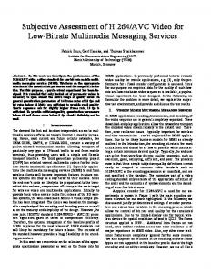
The residual signal is analyzed using the 4-band Wavelet Transform in gure 2. This con guration was chosen since it roughly approximates the critical band divisions. We use the technique presented in [10] for the design and construction of the Perfect Reconstruction (PR) 4-band lter banks. The lter coe�cients selected for the 4-band lters are 32-taps each and have a regularity of K = 3. In [10], the impulse response of the 4 lters are designed to be numerically identical except for a shu�ing operation on the positions of the coe�cients. Overall, we have identi ed a number of key advantages with the proposed lter bank over the CCQF implementation in [2]. These include : � Low computational complexity in 4-band ltering operations [10]. � The delay in subband ltering is small since only three stages are used. � The subband lters are linear phase.
3. QUANTIZATION 3.1. Harmonic Coding A. Frequencies
Since the harmonics are complex conjugates, p=2 harmonic frequencies only need to be encoded where p is the model order. The approach taken for encoding the frequencies was to break the 0-22 kHz range into three frequency regions The three regions 0-2.2, 2.2-5.5 and 5.5-22 kHz were selected because of the decreasing frequency resolution of human hearing as the frequency increases. Then, for each frequency region, the harmonic frequencies are uniformly quantized using 8 bits. Hence the frequencies in the lower region are e�ectively quantized more accurately then the frequencies in the middle region and so forth.
B. Amplitudes and Phases
Like the harmonic frequencies, only p=2 amplitudes and phases need to be encoded. The harmonic amplitudes are rst encoded using a gain value. The gain is computed by nding the power of two which is just greater than the maximum of the absolute value of the amplitude vector. The gain is quantized by computing log2 (gain). We found that 5 bits were necessary to fully represent the dynamic range of log2 (gain). Each amplitude is then normalized by dividing by the gain. The normalized amplitudes are then uniformly quantized with 6 bits. Similarly, the phases are uniformly quantized with 6 bits. Further rate reduction is obtained by Hu�man coding the quantized normalized amplitudes.
3.2. Wavelet Coding
The technique for encoding the Wavelet Transform coe�cients is similar to the MPEG codec [1]. For each subband a scalefactor is extracted. Here, the scalefactor is computed in the same manner as the harmonic amplitude gain. Similarly, 5 bits are su�cient to represent the dynamic range of each scalefactor. Each subband is then divided by its respective scalefactor. The normalized coe�cients are uniformly quantized using the number of bits determined from the bit allocation algorithm. Again, further rate reduction is obtained by Hu�man coding the quantized scalefactors and normalized coe�cients.
4. AUDIO CODING RESULTS
Comparisons to original source material were made for signals encoded and decoded with the proposed coder at encoding bitrates ranging from 60-70 kb/s. Listed in table 1 are twelve source signals from the European Broadcasting Union SQAM CD that were selected for testing. For each audio signal, the nominal encoding bitrate and the segmental Signal-to-Noise Ratio (SNR) are also given in table 1. In general, higher mean segmental SNRs were recorded for the \tonal-like" signals ( e.g. piano and ute), while smaller values were recorded for broadband and transient like signals (e.g. castenets and eddie rabbit). As well as segmental SNRs, informal listening tests were performed by using an A-B-C-A test sequence. In this sequence, A is original source, while one of B and C is the coded signal and the other is a reference signal. In each test, the reference signal was the MPEG layer III encoded/decoded signal (with an encoding bitrate of 64 kb/s). Six people were selected for listening tests and each test was
conducted with headphones in a quiet o�ce environment. For each test signal, the listener was asked to compare the quality of the two coded signals, B and C. Impairments were not noticeable for the acoustic guitar, eddie rabbit, castenets and the female speech after encoding-decoding with the proposed coder. For these signals, the proposed coder delivered similar quality to the MPEG layer III coder. Slight impairments were identi ed for the remainder of the test signals and in each case the MPEG layer III coder delivered a slightly better coded signal quality.
5. DISCUSSION
In this paper, we have investigated combined harmonicwavelet coding of audio signals at low bitrates. Compared to previously proposed methods, di�erent harmonic analysis-synthesis and wavelet ltering schemes have been used here. The proposed coder is capable of delivering excellent signal quality for some of the signals tested at low bitrates (especially \tonal-like" signals). To obtain a more improved coded signal quality for all signals, we believe further research is necessary in identifying the optimum number of bits on a frame-by-frame basis for the harmonic and wavelet coding, the optimum wavelet ltering con guration (i.e. number of subbands) and the lter coe�cients.
REFERENCES
[1] K. Brandenburg and G. Stoll, \The ISO/MPEG-Audio Codec: A generic standard for coding of high quality digital audio", Presented at 92nd AES Convention, Vienna, Austria, March 1992. [2] D. Sinha and A. Tew k, \Low bit rate transparent audio compression using adapted wavelets", IEEE Trans. on Signal Processing, 1993, 41(12):3464-3479. [3] S. Boland and M. Deriche, \Audio coding using the Wavelet Packet Transform and a combined scalarvector quantization", Proc. ICASSP, pp. 1041-1044, Atlanta, GA, May 1996. [4] K. Hamdy, M. Ali and A. Tew k, \Low bit rate high quality audio coding with combined harmonic and wavelet representations", Proc. ICASSP, pp. 10451048, Atlanta, GA, May 1996. [5] D. Sinha and J. Johnston, \Audio compression at low bitrates using the a signal adaptive switched lterbank", Proc. ICASSP, pp. 1053-1056, Atlanta, GA, May 1996. [6] P. Noll, \Wideband Speech and Audio Coding", IEEE Commun. Magazine, 1993, 31(11):34-44. [7] S. L. Marple, Digital Spectral Analysis with Applications, Prentice Hall, Englewood Cli�s, New Jersey, 1987. [8] G. H. Golub and V. Loan, Matrix Computations, Baltimore, MD, John Hopkins University Press, 1983. [9] MD. Anisur Rahman and Kai-bor Yu, \Total Least Squares Approach for Frequency Estimation using Linear Prediction", IEEE Trans. ASSP, 35(10):1440-1454, October 1987. [10] O. Alkin and H. Calgar, \Design of E�cient M-Band Coders with Linear-Phase and Perfect-Reconstruction Properties", IEEE Trans. Signal Processing, 1995, 43(7):1579-1589.
Harmonic Side Information
Masking Model f Time Signal Frame (s) (512 samples)
k
Harmonic Analysis
{f k, A k,
k
}
Quantizer Encoder Bitstream Noise Masking Model
Harmonic Reconstruction
-
Bit Allocation Algorithm
h
+
Wavelet
r
Quantizer
Transform
Figure 1. Proposed Audio Encoder
RESIDUAL SIGNAL (0-22000 Hz)
16500 - 22000 Hz 11000 -16500 Hz 5500 - 11000 Hz
4-channel
4125 - 5500 Hz 2750 - 4125 Hz 1375 - 2750 Hz
4-channel
4-channel
Figure 2. Proposed wavelet ltering scheme
Audio Signal Bitrate (kb/s) Segmental SNR (dB) Eddie Rabbit 67 18 Castenets 70 12 Bass Vocal 60 24 Acoustic Guitar 64 23 Female Speech 66 19 Glockenspiel 63 26 Male Speech 65 19 Piano 65 38 Triangle 65 27 Violin 65 25 Flute 64 34 Gong 63 31 Table 1. Nominal Encoding Bitrate and Segmental SNR for each test signal.
1031 - 1375 Hz 688 - 1031 Hz 344 - 688 Hz 0- 344 Hz