Nimrod/K: Towards Massively Parallel Dynamic Grid Workflows § David Abramson, § Colin Enticott and † Ilkay Altinas {david.abramson, colin.enticott}@infotech.monash.edu.au,
[email protected] § Faculty of Information Technology, Monash University, Clayton, 3800, Victoria, Australia
Abstract A challenge for Grid computing is the difficulty in developing software that is parallel, distributed and highly dynamic. Whilst there have been many general purpose mechanisms developed over the years, Grid programming still remains a low level, error prone task. Scientific workflow engines can double as programming environments, and allow a user to compose ‘virtual’ Grid applications from pre-existing components. Whilst existing workflow engines can specify arbitrary parallel programs, (where components use message passing) they are typically not effective with large and variable parallelism. Here we discuss dynamic dataflow, originally developed for parallel tagged dataflow architectures (TDAs), and show that these can be used for implementing Grid workflows. TDAs spawn parallel threads dynamically without additional programming. We have added TDAs to Kepler, and show that the system can orchestrate workflows that have large amounts of variable parallelism. We demonstrate the system using case studies in chemistry and in cardiac modelling.
1
Introduction
Grid computing has been proposed as the next generation of infrastructure to support distributed applications in science, engineering and business [13][14][20]. The Grid provides mechanisms that harness computational resources, databases, high-speed networks and scientific instruments, allowing users to build innovative virtual applications. Such virtual applications are synthesized by combining multiple different components on multiple computational resources. A significant challenge for Grid computing is the difficulty in developing software that is concurrent, distributed and highly dynamic. There have been many mechanisms developed over the years for building such systems, ranging from remote procedure calls, general IPC mechanisms like TCP/IP sockets, parallel computing techniques based on message passing, through to recent work in Web services. However,
† San Diego Supercomputer Center, 9500 Gilman Drive, MC 0505 La Jolla, CA 92093-0505, USA. programming still remains a low level and error prone task. Recently, a number of different groups have developed scientific workflow engines that can double as programming environments for the Grid. These Grid Workflow systems [17][23][5][4][19][11][18][27] [10][12] [24][31][32][33][34] allow a user to compose a complex virtual application based on pre-existing, in some case, legacy components. In this model, components typically take input and produce output as part of a pipeline. The workflow system schedules the computations on the most appropriate (or selected) resource only when the inputs are available. Likewise, when the output is produced, it is forwarded to the next computation in the pipeline. Grid Workflows have been applied to diverse fields such as Computational Chemistry [5], Ecology [4] and Bioinformatics [19]. However powerful, current workflow engines are remarkably static – that is, the workflows themselves do not typically change at run time. Importantly, parallelism is typically specified statically when the underlying workflow graph is generated. Because of this, there are usually only two ways to specify parallel activity in a workflow: 1. Build a graph with multiple independent subgraphs; or 2. Create a graph that contains logic to spawn parallel activities. The first of these means that the amount of parallelism cannot change once the graph has started execution, which is restrictive. Further, if there is a lot of parallelism, the graph can become very large and difficult to manage. For example, a workflow that wishes to process the contents of a database, in parallel, must be replicated many times to allow them to run in parallel. The underlying graph can become very large, but it also contains a high degree of redundancy since the same operations are applied to each database element. This is the approach taken with tools like APST [8]. The second approach can support dynamic parallelism, but requires the user to write a very complex graph. For example, users must explicitly code for parallel execution, and incorporate loops that process the contents of the database, provide
Permission to make digital or hard copies of all or part of this work for personal or classroom use is granted without fee provided that copies are not made or distributed for profit or commercial advantage and that copies bear this notice and the full citation on the first page. To copy otherwise, to republish, to post on servers or to redistribute to lists, requires prior specific permission and/or a fee. SC2008 November 2008, Austin, Texas, USA 978-1-4244-2835-9/08 $25.00 ©2008 IEEE
mechanisms that spawn independent calculations and then synchronize the results. This process significantly complicates the task of writing a workflow. In spite of this, the approach is typical of systems like Kepler [17] [23] and Taverna [19], for example. Over the years we have developed expertise in massively parallel parameter sweep workflows, using the Nimrod family of tools [3]. Nimrod is a system that makes it very easy to build parameter sweep and search applications. Users can run an arbitrary executable image, varying a number of parameters. Nimrod contains tools that perform a complete parameter sweep across all possible combinations (Nimrod/G), or search using non-linear optimization algorithms (Nimrod/O) [1] or experimental design techniques (Nimrod/E) [25]. Importantly, the number of jobs, and thus the parallelism, can be varied at run time, and the Nimrod scheduler places tasks on the available resources at run time. However, Nimrod was not designed to execute arbitrary workflows of the type discussed above. Thus, it is difficult to run sweeps over workflows, and workflows containing sweeps. Likewise, as illustrated, most workflow systems do not support the parallel execution of tasks that is supported in Nimrod, and are not well suited to parameter sweeps and searches. In this paper, we discuss an approach that allows workflows to spawn parallel threads dynamically without additional programming. Users write the simplest possible workflow that captures their business logic, and the underlying system provides mechanisms to replicate it, at run time, as required. This approach makes it possible to use the same workflow with one or a million data values, regardless of the nature of the logic. It allows a user to mix sweeps over workflows and workflows that contain sweeps. We have implemented a prototype tool called Nimrod/K that demonstrates the new mechanisms. Nimrod/K is built on Kepler’s runtime engine (Ptolemy) [18]. It uses a dataflow execution model that was originally developed for highly parallel dataflow computers in the 1980’s, and this provides an extremely rich execution mechanism. It leverages a number of the techniques developed in the earlier Nimrod tools for distributing tasks to the Grid. The paper begins with a discussion of existing workflow engines, and in particular, discusses Kepler (as a typical one). We then discuss the tagged dataflow architecture, independently proposed by groups at MIT [6] and Manchester [16], and show how this provides an ideal mechanism for executing dynamic workflows. We then discuss our prototype implementation, followed by a few case studies.
2
Grid Programming in Kepler
Kepler is typical of many modern Grid workflow systems. It allows scientists from multiple domains to design and execute scientific workflows. Scientific workflows can be used to combine data integration, analysis, and visualization steps into larger, automated "scientific process pipelines" and "Grid workflows" [23][5]. Kepler builds upon the Ptolemy II framework [18] developed at the University of California, Berkeley. Ptolemy II is a Java-based software framework with a graphical user interface called Vergil. The Ptolemy II project studies modeling, simulation, and design of concurrent, real-time, embedded systems. The focus is on assembly of concurrent components. The focus of the Ptolemy II system is to build models of systems based on the assembly of predesigned components. These components are called actors: “An actor is an encapsulation of parameterized actions performed on input data to produce output data. An actor may be state-less or state-full, depending on whether it has internal state. Input and output data are communicated through well-defined ports. Ports and parameters are the interfaces of an actor. A port, unlike methods in Object-Oriented designs, does not have to have call-return semantics. The behaviors of a set of actors are not well-defined without a coordination model. A framework is an environment that actors reside in, and defines the interaction among actors.” [18]. The interaction styles of actors are captured by Models of Computation (MoC). A MoC defines the communication semantics among ports and the flow of control and data among actors. “Directors” are responsible for implementing particular MoCs, and thus they define the “orchestration semantics” of the workflow. Simply by changing the director of a workflow, one can change the scheduling and overall execution semantics of a workflow, without changing any of the components or the network topology of the workflow graph. Two directors that are commonly used for Grid programming are the Process Networks (PN) and the Synchronous Data Flow (SDF) directors, which are based on Kahn Process Networks. A Process Network is a directed graph, comprising a set of nodes (processes) connected by a set of directed arcs (representing FIFO queues). Each process executes as a standalone sequential program and is wrapped as a Ptolemy II actor. The one-way FIFO channels are used for the communication of processes and each channel can carry a possibly infinite sequence (a stream) of atomic data objects (tokens). Since channels have, in principle, unbounded capacity, writes
to channels are non-blocking, while reads are blocking [18]. The SDF domain is a dataflow-based execution model in which a sequential execution order of actors can be statically determined prior to execution. This results in execution with minimal overhead, as well as bounded memory usage and a guarantee that deadlock will never occur. Kepler extends PtolemyII with a significant number of actors aimed particularly at scientific applications, e.g., for remote data and metadata access, data transformations, data analysis, interfacing with legacy applications, web service invocation and deployment, provenance tracking, etc. Kepler also inherits from Ptolemy the actor-oriented modeling paradigm. In spite of its significant power, Kepler, and many other current workflow systems, do not support dynamic parallel execution. Thus, as discussed in the introduction, users must explicitly code a workflow to cause it to execute elements in parallel – either by replicating the workflow statically, or adding looping constructs that scatter and gather threads. Both of these techniques significantly complicate the workflow and obscure the underlying business logic. In the next section we discuss a tagged dataflow architecture, and show that it provides a much richer execution environment for parallel workflows.
3
The Tagged Dataflow Architecture
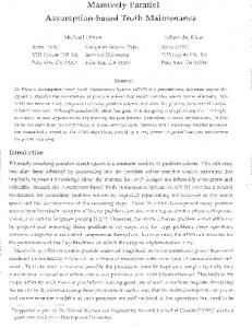
Arvind and Nikhil, at MIT, and separately Gurd and Watson at Manchester, proposed a multiprocessing architecture that supports parallel execution of instruction streams. Both of these architectures execute programs as “graphs” that represent a machine instruction sequence for a given program. The underlying model assumes that an instruction can ‘fire’ when it has its operands, unlike the conventional VonNeumann model in which an instruction fires when selected by the program counter. In a dataflow machine, multiple instructions can fire concurrently, and provided they are scheduled to different processing elements, the program can be executed in parallel. A number of dataflow machines were produced, however, the additional hardware complexity made them uncompetitive with Von Neumann machines of the time. Figure 1 illustrates the basic principles of a dataflow machine. Here, the node of graph represents an arbitrary instruction, and tokens contain the value of each operand. Instructions, or nodes, consume and generate tokens. In step (a) a token arrives on one input of an instruction. In step (b) a token arrives on the other input. In step (c) the instruction fires, consuming the tokens on the inputs, and generating token on the
output. When connected together, these instructions can be used to implement arbitrary complex programs.
Figure 1 – instruction sequencing in a dataflow machine In tagged token machines, tokens contain both a data field and a special tag field – or “colour”, which is used to separate threads of execution. Importantly, an instruction fires when it has a token on each of its inputs that have the same colour values. Parallelism is implemented simply by creating tokens with different colours. Figure 2 shows an example. Here three tokens are stored on the left input of the instruction, each with a different colour. When tokens of the same colour arrive on the other input, the node fires. However, because each token has a different colour, three instances of the node execute in parallel. The output tokens are coloured the same as the inputs, and thus, as long as the colours remain distinct, the graph executes in parallel. It is worth noting that the machines include a number of colour manipulation instructions, and this makes it possible to both change the amount of parallelism dynamically, but also to change it in different parts of the graph. For example, it is not uncommon to spawn a number of concurrent threads for, say, parallel loops, and then collect the outputs back into a sequential instruction steam.
Figure 2 – instruction sequencing in a tagged dataflow machine It is not possible to give a full description and all of the complexities of the instruction sets of the Manchester and MIT machines here. What is important is the idea of distinguishing concurrent threads of execution by colouring the tokens that flow through the graph. The architecture used in this work builds on a generalisation of the tagged architecture, and was proposed by Abramson and Egan [2]. This
generalisation allows tokens with the same colour to form a queue, and thus the model allows both queued (sequential) and tagged (parallel) execution. As it turned out these techniques were not particularly successful for scheduling individual instructions at the machine code level, because the hardware and software overheads are substantially more than the cost of executing a single instruction. Thus, dataflow machines never achieved acceptance as a viable parallel architecture. However, the tagged dataflow idea can be used to support the type of dynamic parallelism discussed in this paper where the computations are much more significant than individual instructions, and thus the overhead is minimal. In the next section we will describe how we have used these ideas in the Nimrod/K tool set.
4
Design of Nimrod/K
In Section 2 we introduced the way Kepler (and the underlying Ptolemy) supports the use of different execution models with the same workflow. One of the reasons we have based our implementation on Kepler is that this important separation of concerns makes it possible to introduce a new execution mechanism based on the tagged dataflow execution model whilst leveraging the existing infrastructure. Accordingly, we have implemented a new Director called the Tagged Dataflow Architecture (TDA). The TDA builds on the existing SDF and PN directors but tags (or colours) tokens to distinguish different threads of execution. We envisage the idea could be added to other workflow engines with an ability to add new execution mechanisms. The TDA director supports existing ‘legacy’ actors in the PtolemyII project and the newer actors developed for Kepler, making a diverse range of actors available. In the TDA, threads are identified by adding a unique tag to each token. These tag values are manipulated by a set of special tag manipulation actors, although the tag flow implementation is usually hidden from workflow designers. Even though some of Ptolemy II data types can be large complex structures, the implementation minimises memory usage by using pointers to the structure containing each token in the thread. This means the implementation scales well as the number of threads increases. Underlying the SDF and PN directors are FIFO queues located on each of the inputs on an actor. Normally, when multiple tokens arrive on an input port, they are queued and can be processed when the actor is available. The TDA director follows the same procedure, but with a separate queue for tokens with different tags. This means that multiple tokens with the same tag value queue up, whereas tokens with
different tag values can be consumed in parallel. Multiple actors cannot read from the same queue because they only read from queues with the same tag value assigned to them, and no two actors are given the same tag value. This gives the ability to copy actors (PtolemyII calls this cloning) and invoke them using different tags simultaneously. Importantly, this approach requires no changes to existing actors, which are usually unaware that they have been cloned. We offer three methods to assign and modify tags within a workflow. The first two are aimed at the workflow creator who wishes to parallelize execution of a workflow. The third is aimed at the actor developer who wishes to develop new actors that support parallel threads. The first method is transparent to workflow designers, and involves a number of new actors that generate and consume tagged tokens. For example, the Parameter Sweep actor shown in Figure 3 generates tokens that are already tagged. One could imagine a small set of such actors, such as reduction operators, etc. Clearly, this method is preferred because the parallelism is implicit in the workflow specification, and no explicit tag manipulation is required. Thus, this method makes it possible to take existing workflows and parallelise them without modification to the core logic. The second method provides a special tagging actor that adds a tag to a given token. This actor has two inputs, one of which takes a tag and the other takes an arbitrary token. The output of the actor is a token with its tag set. The third method, which is directed at actor developers, provides an API that allows tagging, retagging or removing the tag of a token. This means that a developer can write complex actors that abstract tag management from the workflow creator, but still expose sophisticated thread management techniques. Likewise, we have provided two methods to access the values assigned to the tag from both the workflow design and from within an actor’s code. First, when an actor is invoked, the tag value of its input tokens is added to the actor’s parameter scope making it available in the actor’s parameter options for a workflow creator to use. Second, we provide API functions so that actor developers can also access this information.
Figure 3 – a simple Kepler workflow Figure 3, shows a simple parameter sweep experiment executing over an application called “My
program”. In this example, the parameter sweep actor produces a number of tokens, each containing one of the parameter combinations (stored in a record). When using the TDA director, these tokens are also tagged with the value of the record. For example, if the value of the record is “X=1, Y=1”, then the value of the tag is “X=1, Y=1”. The “My program” actor accepts one token and produces one token as output, whilst the Display actor displays any tokens it receives. We will now compare the different behaviour of the SDF, PN and TDA directors as they orchestrate this simple workflow. The SDF director [22] is a fully synchronised and pre-scheduling MoC. It executes its actors in turn until every actor reports it is unable to execute. The PN director, on the other hand, [22] activates every actor simultaneously and blocks an actor when there are no tokens available. Therefore, when executing the workflow in Figure 3 under the PN director, all actors are activated simultaneously and the “My program” and the Display actors are blocked immediately. As the parameter sweep actor produces tokens, the “My program” actor proceeds to process the tokens one at a time. Likewise the Display actor displays the tokens as they arrive. As it turns out, both the SDF and the PN directors behave in similar ways for this simple workflow.
Figure 4 – The TDA director executing the simple workflow Whilst the TDA director uses the same requesting technique as SDF, it also has the ability to create new threads for each of the tokens that it generates. In this example, the TDA director creates a single thread for the parameter sweep actor, which sequentially sends tokens to the “My program” actor. However, since each output token from the parameter sweep actor is tagged with a different value, multiple copies of “My program” execute in parallel. Importantly, the output of the “My Program” actor is tagged with the same
value as its input, and thus, each “My program” thread communicates with a different Display actor thread. The effect of this is that the TDA director creates a separate thread for each of the parameter combinations and, as shown in Figure 4, they each display in parallel. It is important to highlight that Figure 4 depicts the run-time behaviour of the workflow, whereas, Figure 3 shows the workflow as designed. A more complex workflow would probably gather or reduce the outputs of “My Program” together into a single thread, possibly reordering them into a single queue based on their tag values. This is analogous to a scatter-gather operation in a vector processor or a parallel loop instruction in a programming environment, and achieves the same sort of parallel execution. Comparing directors shows the concurrency benefit of using the TDA director and how actors remain unmodified in all environments. Many of the Grid actors in Kepler do not provide information on the consumption and firing rate of tokens. In the example given in Figure 3, it may not be clear how many tokens the “My program” actor needs to consume nor how many tokens it will eject for each firing and if these numbers remain consistent. As discussed in [22], the SDF director determines a schedule for a workflow at the start of the execution. Because of this, it is unable to handle non-deterministic actors that change their token usage behaviour during the execution while the PN director adapts to the changing state. In this sense, the TDA director is similar to the PN as its schedule is not fixed. State fullness is another attribute of an actor that needs to be considered. State fullness is where an actor holds information from a previous firing making the order of tokens entering the actor important. This can also happen indirectly through shared resources. These types of actors are safe using the SDF and PN directors as there is only one copy of the actor on the workflow. These actors are supported with the TDA director, but may be of limited value as they may not be able to be cloned because of concurrency issues, and thus, should be used with caution. The TDA environment allows both the actor developers and the workflow designers to specify if and when an actor can be cloned. Issues relating to state and parallelism will be discussed in further work.
5
Implementation Details
Figure 5 shows the structure of our prototype director implementation. There are three main components: the token scheduler, the actor manager and the director. The token scheduler’s role is to decide which tag an actor should process next. The actor manager is
responsible for the execution of an actor, and for maintaining all of its copies. Like all directors in PtolemyII and Kepler, the TDA director maintains the execution of the workflow and reports to the workflow’s calling function. The token scheduler is responsible for deciding the actor firing order and the assignment of tokens to actor clones. The scheduler is notified of all token, movements and is responsible for deciding the number of actor copies that should be cloned at any time. This dynamic scheduling is different from the static scheduler used by the SDF director and the blocking method used in the PN director. We have also added a actor base class with an API that allows the scheduler to query the actor’s resource requirements. A scheduler needs to consider resource availability to improve its scheduling even when using local resources. For example, a workflow may run a CPU intensive simulation package such as MATLAB which might be executed on a multi-processor. In this scenario, it is important for the scheduler to know how many MATLAB computations it can execute concurrently. Further to this, MATLAB might appear more than once in the workflow which needs consideration when scheduling these computations concurrently. It is the scheduler’s responsibility to coordinate shared resources across the workflow. TDA Director
Token Scheduler
Actor Manager Nimrod Actor Manager Original Nimrod Actor Manager Actor
Token Queues
Actor Copies
Figure 5 - Object associations The prototype token scheduler is based on a simple outstanding request queue where an entry is added when a token arrives on any actors’ input ports. The entry holds a reference to the actor and a reference to the token’s tag’s value, and ensures that all outstanding requests are processed before terminating the workflow. Storing references to these objects does not create inconsistency issues because actors are never
changed during execution and tags are immutable in this environment. Only one outstanding request is kept per actor and tag combination to avoid unneeded multiple requests that will increase the queue size. This has the most noticeable effect when an actor requires more than one token to fire, but will only need a single firing request. Storing requests this way reduces the memory requirement of the queue because the actor only needs to be flagged once to execute. When an actor finishes firing and reports that it can fire again, the token scheduler decides whether to requeue this actor and tag combination by checking if there are any outstanding tokens. The only exception are actors that are defined as “source” actors which always generate a new request after a successful fire until the actor reports it is no longer able to fire. Our prototype token scheduler currently clones as many actors as required to consume all outstanding tokens at that time. However, this strategy may generate a large demand on resources including memory, in both the number actors and the number of active tokens, and on shared resources. Similar issues have been addressed in the past with the k-bounded loops work of Culler [9] and we plan to integrate some of these ideas in the near future. Actor managers are responsible for maintaining the actors on the workflow. There is one actor manager for each actor on the workflow. They provide all the functions required to maintain an actor, including functions that manage actor cloning, token inputs and outputs, initialisation and cleaning up. Importantly, actors do not require modification to work under the TDA director because the actor manager performs all the functions required. These functions include the interface for a scheduler to query an actor’s resource needs. The actor manager adds the tag’s content (assigned by the token scheduler) to the actor’s parameter scope and it ensures outgoing tokens have the correct tag for the actors that do not manage the tag itself. The TDA director is invoked in the same way SDF and PN directors. Importantly, it is built on the same director interface as SDF and PN, and this allows it to interact seamlessly with the Ptolemy environment. It also has the functions to maintain synchronisation betweens the threads in its environment. An important design feature of Kepler (and Ptolemy) is the use of multiple directors on the same workflow by using a hierarchical layout. This is implemented using special “Composite Actors” that supports nesting of directors. Just as PN directors allow an SDF controlled sub-graph actor in its workflow, a TDA controlled sub-graph can also be part of a PN controlled workflow. Further to this, it is possible to have an SDF sub-graph inside a TDA
workflow. There are rules governing which directors can be nested as a sub-graph on a workflow, which are explained in [15]. The TDA director closely resembles PN director on which combinations are possible with one exception, it is possible to have TDA controlled sub-graph as part of an SDF controlled workflow. This is because the TDA director does not block on reads and can release control back to the SDF director when no internal actor is active. To complicate the issue, placing a PN director inside a TDA controlled workflow blocks the TDA director from releasing control back to an outlying SDF controlled workflow. This is because PN directors do not relinquishing execution until it is told there are no more tokens at which point it terminates completely. We are currently exploring the semantics of nesting TDA with other directors and will produce a set of templates with clearly defined semantics for workflow developers.
6
Case Studies
In this section we demonstrate the effectiveness of our work using two case studies in theoretical chemistry and cardiac cell modelling. We have deliberately chosen fairly simple workflows as demonstrators in this paper to avoid complicating the description of the problem domains and the workflows. However, the same techniques have been applied to more complex examples in quantum chemistry, and will be reported in the future.
6.1
our previous work we used Nimrod/G to schedule and execute the calculations. The workflow shown in Figure 6 depicts the computation, which involves the execution of the GAMESS quantum chemistry package [26][21] a number of times, across a search space defined by 4 parameters (A, B, C and D). Here parameters A, B, C and D are to be determined that will provide the best fit between the real atomic system and target properties of the pseudo atom. The experiment used the results of the very large sweep over the A, B, C, D parameter space.
Case study 1 – Quantum Chemical Calculations
The first experiment concerns quantum chemical models – based on the Schrödinger equation – of assemblies of atoms as found in large biomolecules. To date, it has been impossible to use quantum methods on such large molecules because the computational time becomes prohibitive. This work involves a set of approximations that replace large multi-atom systems with a single “pseudo” atom that has special theoretical properties that make it an analogue for the larger system. The solution involves computing a potential surface for the pseudo atom, called a pseudo-potential, and using this in the quantum calculations. A pseudo-potential does not describe a real chemical system, but can be used to approximate, and replace, a much larger molecular system. The result is that the quantum chemical calculations are much simpler, and faster, than if the original molecule had been used, opening the possibility of using quantum methods on very large systems. The details can be found in [28][29][30]. In
Figure 6 – GAMESS Workflow The workflow shows 4 separate executions of GAMESS for each parameter set. The Parameter Sweep actor computes all combinations of the A, B, C and D, and builds a record for each of these combinations. They are used as inputs to the GAMESS actors, and the outputs are sent into an actor that computes the Root Mean Square error of the cost function. This is a measure of how well a particular pseudo potential surface fits calculations of a real molecule. The results are re-ordered and plotted using a Graph actor. Figure 7 shows the results across two of the parameters. The remaining parameter can be varied to produce multiple images, which can then be composed into a movie. In the experiment we executed the workflow with three different Directors – SDF, PN and TDA. We highlight the simplicity of changing the execution semantics – all we had to do to change them was to swap out one director on the Vergil canvass and replace it with another one. Figure 8 shows the performance of the workflow under each of the Directors running on the testbed shown in Table 1. All compute resources have little communication latency (


![FREE [DOWNLOAD] PROGRAMMING MASSIVELY PARALLEL ...](https://m.moam.info/img/260x300/free-download-programming-massively-parallel-_64789e54097c4744708d088f.jpg)