WSN model using coronas concentric to the sink. (a) Uniform distribution, (b) Non-uniform distribution. first [8], resulting in holes in the WSN. This uneven energy.
Non-Uniform Sensor Deployment in Mobile Wireless Sensor Networks Mihaela Cardei, Yinying Yang, and Jie Wu Department of Computer Science and Engineering Florida Atlantic University Boca Raton, FL 33431 Email: {mihaela@cse., yyang4@, jie@cse.}fau.edu
Abstract—In wireless sensor networks (WSNs), good sensor deployment is vital to the coverage of the monitored area and to the network lifetime. To improve the initial deployment, one possible method is to use mobile sensors, thus allowing sensors to relocate. In order to prolong network lifetime and achieve balanced energy consumption, one approach is to place sensors in different densities which vary with the distance to the sink. Since sensors located closer to the sink are involved in more data forwarding, sensors in this region should have a higher density. Movement-assisted sensor deployment involves moving sensors with the purpose of meeting the density requirements according to their distance to the sink. The additional requirement of coverage is also discussed. In this paper, we address the problem of Movement-assisted Sensor Positioning (MSP) to increase network lifetime with the objective to achieve the theoretical sensor densities while minimizing sensor movement. We propose three solutions to the MSP problem: an IntegerProgramming formulation, a localized matching method, and a distributed corona-radius scanning algorithm. Simulation results are presented to verify the effectiveness of the proposed solutions.
I. I NTRODUCTION A wireless sensor network (WSN) consists of a large number of sensor nodes that are densely deployed either inside the phenomenon or very close to it [1]. Sensor nodes measure various parameters of the environment and transmit data collected to one or more sinks using hop-by-hop communication. Once a sink receives sensed data, it processes and forwards it to the users. In mobile sensor networks, sensors can selfpropel, can move using wheels [4], springs [2], or they can be attached to transporters such as robots [4] and vehicles [6]. A large number of sensors can be distributed in mass by scattering them from airplanes, rockets, or missiles [1]. The initial deployment is hard to control using such deployment mechanisms. However, a good deployment is vital in order to improve coverage, achieve load balance, and prolong the network lifetime. In general, there are two methods used to improve the initial deployment: by deploying additional sensors [5] or by movement-assisted sensor positioning mechanisms [2], [11], [13], [14]. In a WSN, sensors closer to the sink tend to consume more energy than those farther away from the sink. This is mainly because, besides transmitting their own packets, they forward packets on behalf of other sensors that are located farther away. If sensors in the network are uniformly distributed, then the sensors closer to the sink will deplete their energy resources
d
C3
C2
C1
ρ3 0000 1111 1111 0000 0000 1111 0000 1111
ρ2
ρ1
0000 1111 0000 1111 1111 0000 0000 1111
Message Transmission Path
(a)
(b)
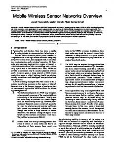
Fig. 1. WSN model using coronas concentric to the sink. (a) Uniform
distribution, (b) Non-uniform distribution.
first [8], resulting in holes in the WSN. This uneven energy consumption will reduce network lifetime. In [8], Olariu et al. consider a uniform sensor deployment and divide the monitored area in coronas as illustrated in Figure 1a. A message transmitted from corona Ci is forwarded by sensor nodes in coronas Ci−1 , Ci−2 , and so on until it reaches corona C1 from where it is transmitted to the sink. Corona width is chosen such that a message is forwarded by only one sensor in each corona. Assuming that each sensor is equally likely to be the source of a path to the sink, sensors suffer an uneven energy depletion, with sensors in the first corona being the first to die. This may result in network partitioning, with other sensors being unable to report their data to the sink. Many papers covering the topic of sensor repositioning do not consider the issue of uneven energy depletion with distance to a predetermined sink; they are mainly concerned with uniformly distributing the sensors to provide load balancing and area coverage. In this paper, we consider a sink located in the center of the monitored area and propose algorithms to create a sensor movement plan that (1) achieves the desired sensor densities for uniform energy depletion (see Figure 1b), and (2) minimizes the distance that the sensors move. The rest of this paper is organized as follows. Section II presents related works on sensor redeployment mechanisms. Section III shows the non-uniform sensor density computation and introduces the MSP problem definition. We continue in Section IV with three solutions for the MSP problem and their performance evaluation is presented in Section V. We conclude
2
TABLE I PARTITIONING THE MONITORED AREA IN CORONAS , NOTATIONS . Ci ρi A T d n N Ni Rc Rs
The ith corona The computed, ideal density of corona Ci Area of the whole monitored area Data reporting interval Width of each corona Number of coronas Total number of sensors Number of sensors in corona Ci Communication range of a sensor Sensing range of a sensor
our paper in Section VI. II. R ELATED W ORKS The sensor placement issue has been widely studied recently [3], [7]. There are recent research works focusing on improving the initial deployment of WSNs using sensors’ mobile ability [2], [11], [13]. Some research works (e.g. [2], [14]) provide centralized sensor deployment mechanisms, while others (e.g. [11], [13]) present distributed protocols. In [2], Chellappan et al. study the flip-based deployment mechanism to achieve the maximum coverage. They assume the sensor can only flip once, and divide the whole network into multiple square regions. The centralized algorithm maximizes the number of regions that are covered by at least one sensor node with the minimum moving cost. Wu and Yang introduce SMART [13], a scan-based distributed protocol with the goal of uniformly distributing sensors via sensor relocation. A scanning mechanism is used to balance the number of sensors first for each row of clusters and then for each column of clusters. In [11], Wang et al. present VEC, VOR, and Minimax algorithms. To maximize the coverage, in VEC, sensors that are too close to each other will be pushed away by the virtual force. In VOR, when a node senses the coverage hole, it is moved towards the farthest vertex in the Voronoi polygon. The Minimax algorithm is similar to VOR; the virtual force will pull sensors to sparser areas. In [12], the authors proposed a grid-quorum solution to quickly locate the closest redundant sensors to the target area, where a sensor failure occurs. In [14], Yang and Cardei use a partitioning of the monitoring area in coronas, and consider a one-time sensor flip mobility model to reposition sensors to prolong network lifetime while ensuring area coverage. The centralized sensor movement plan is computed by the sink using a max-flow min-cost approach. Similar to [2], [11], [13], [14], we use sensor mobility to relocate them after the initial deployment. However, the goals in [2], [11], [13] involve improving the coverage and achieving load balance with uniform sensor densities. In [14], the goal is to achieve non-uniform sensor densities using a centralized algorithm when sensors can move by flipping at most once. In this paper, we consider a general sensor movement model and propose both centralized and localized approaches that reposition sensors according to the computed non-uniform sen-
sor densities. Using non-uniform sensor densities will prolong network lifetime by balancing sensors’ energy depletion. III. N ON - UNIFORM S ENSOR D ENSITY C OMPUTATION AND P ROBLEM F ORMULATION In this paper, we consider a general architecture where sensors send their measurements to a sink located centrally, as illustrated in Figure 1a. A WSN consisting of a large number of sensor nodes is deployed for periodic data reporting, where one data message per unit of area is transmitted each datareporting-interval T . We consider a monitored area that is virtually divided in coronas, where the width of corona d equals the sensor communication range Rc . In this way, a message originating in corona Ci is forwarded by sensor nodes in coronas Ci−1 , Ci−2 , and so on until it reaches corona C1 from where it is transmitted to the sink. Table I shows the parameter notations used in corona partitioning. We assume that sensor energy consumption is proportional to the number of messages transmitted, and that sensors are uniformly deployed in the same corona. Intuitively, to balance energy consumption, we will deploy the fewest sensors in the last corona Cn and the largest number of sensors closest to the sink, in corona C1 . We define ρi to be the sensor density in the corona Ci , thus ρ1 ≥ ρ2 ≥ · · · ≥ ρn . Our objective is to compute the sensor density of each corona so that all sensors deplete their energy at the same rate. This will balance the energy consumption. For this, we require that each sensor transmits the same number of messages in the time interval T . We model the data gathering as a periodic data reporting process, where one data message is generated from each unit of area during the time interval T . Based on this assumption, a sensor in corona Cn will generate 1/ρn messages each time-interval T . Also note that sensors in Cn do not forward messages on behalf of other sensors. Let us compute the number of messages T otalN umi transmitted by a sensor in corona Ci in time T . The sensor generates 1/ρi messages with its own measurements and participates in forwarding the messages generated by coronas Ci+1 , P Ci+2 , . . . , Cn . Using notations in Table I, we have Pthe n n N = i=1 Ni and A = i=1 Ai . The number of messages generated by all the sensors in corona Ci is Ni /ρi . Thus, the number of messages transmitted by a sensor in corona Ci in T time is: T otalN umi =
1 + ρi
Ni+1 ρi+1
+
Ni+2 ρi+2
n + ... N ρn
Ni
=
Ai+1 + Ai+2 ... + An A − (A1 + A2 + ... + Ai−1 ) 1 + = ρi Ai · ρi Ai · ρi
To balance the energy consumption, we require that sensors in different coronas consume the same energy, which means all sensors send the same number of messages in time T : T otalN umi = T otalN umn A − (A1 + A2 + ... + Ai−1 ) 1 = Ai · ρi ρn
3
d
ρi = ρn ·
A − (A1 + A2 + ... + Ai−1 ) Ai
(1)
Value ρn can be computed based on the total number of sensors N and the coronas areas, as follows: ρ1 · A1 + ρ2 · A2 + ... + ρn · An = A A − A1 ρn · · A1 + ρn · · A2 + ... A1 A2 A − A1 − A2 − ...An−1 · An = +ρn · An ⇒ ρn =
(2)
Combining equations (1) and (2), we can express the density ρi as a function of the total number of sensors, monitoring area, and coronas areas: P A − i−1 N j=1 Aj (3) ρi = P n · Ai j=1 j · Aj Considering n circular coronas P of width d (see Figure 1a), n 2 Ai = π · d2 (2 · i − 1) and A = i=1 Ai = π(nd) . After simple computations, equations (1) and (2) reduce to: N 6n and ρn = · A 4n2 + 3n − 1
6n n2 − (i − 1)2 N · 2 · (4) A 4n + 3n − 1 2·i − 1 Next, we compute the improvement in network lifetime when using non-uniform densities versus the case of uniform sensor deployment. The case of uniform sensor deployment has been addressed in [8] and this work shows that the sensors in the first corona die first, thus limiting network lifetime. Let us consider a uniform sensor distribution with density ρ. The total number of messages T otalN um′1 transmitted by a sensor in corona C1 in time T is: ρi =
T otalN um′1
1 = + ρ
N2 ρ
+
N3 ρ
+ . . . Nρn
N1
=
0000 1111 0000 1111 1111 0000 0000 1111
A 2 ·n N
0011 11 0011 0011 0011 0011 00 11 00 00 11 0011 11 00 0011 11 0011 00 00 11 00 11 00 11 00 11 00 11 00 11 00 11 00 11 00 00 11 00 11 00 11 00 00 00 11 00 0011 11 0011 11 0011 11 00 11 0011 11 0011 11 00 11 00 11 00 00 11 00 00 0011 11 0011 11 0011 11 0011 11 0011 11 0011 11 0011 11 00 11 00 11 00 00 00 00 00 00 11 00 11 1100 00 1100 1100 1100 1100 1100 1100 11 1111 00 0011 11 00 00 00 11 00 11 11 00 00 11 0011 11 0011 0011 0011 0011 00
(b)
B △y=4
A △x=2
(c)
Fig. 2. Division of monitored area in r×r square regions. (a) Division of monitored area in coronas, (b) Division of monitored area in r × r square regions. (c) Manhattan distance between regions A and B.
N
N N = Pn A1 + 2 · A2 ... + n · An i=1 i · Ai
2
C1
(a)
It follows that:
n2 − (i − 1) ρi = ρn · 2·i − 1 It follows that:
C2
N
N n · A − (n − 1) · A1 − (n − 2) · A2 ... − An−1
ρn =
C3
11 00 11 00 11 00 11 00 11 00 11 00 11 00 11 00 11 00 11 00 11 00 11 00 11 00 11 00 11 00 11 00 11 00 11 00 11 00 11 00 11 00 11 00 11 00 11 00 11 00 11 00 11 00 11 00 11 00 11 00 11 00 11 00 11 00 11 00 11 00 11 00 11 00 11 00 11 00 11 00 11 00 11 00 11 00 11 00 11 00 11 00 11 00 11 00 11 00 11 00 11 00 11 00 11 00 11 00 11 00 11 00 11 00 11 00 00 11 00 11 00 11 00 11 00 11 00 11 00 11 00 11 00 11 00 11 00 11 00 11 00 11 00 11 00 11 00 11 11 00 11 00 11 00 11 00 11 00 11 00 11 00 11 00 11 00 11 00 11 00 11 00 11 00 11 00 00 11 00 11 00 11 00 11 00 11 00 11 00 11 00 11 00 11 00 11 00 11 00 11 00 11 00 11 00 11 00 11 00 11 00 11 00 11 00 11 00 11 00 11 00 11 00 11 00 11 00 11 00 11 00 11 00 11 00 11 00 11 00 11 00 11 00 11 00 11 00 11 00 11 00 11 00 11 00 11 00 11 00 11 00 11 00 11 00 11 00 11 00 11 00 11 00 11 00 11 00 11 00 11 00 11 00 11 00 11 00 11 00 11 00 11 00 11 00 11 00 11 00 11 00 11 00 11 00 11 00 11 00 11 00 11 00 11 00 11 00 11 00 11 00 11 00 11 00 11 00 11 00 11 00 11 00 11 00 11 00 11 00 11 00 11 00 11 00 11 00 11 00 11 00 11 00 11 00 11 00 11 00 11 00 11 00 11 00 11 00 11 00 11 00 11 00 11 00 11 00 11 00 11 00 11 00 11 00 11 00 11 00 11 00 11 00 11 00 11 00 11 00 11 00 11 00 11 00 11 00 11 00 11 00 11 00 11 00 11 11 00 00 11 00 11 00 11 00 11 00 11 00 11 00 11 00 11 00 11 00 11 00 11 00 11 00 11 00 11 00 11 00 11 00 11 00 11 00 11 00 11 00 11 00 11 00 11 00 11 00 11 00 11 00 11 00 11 00 11 00 11 00 11 00 11 00 11 00 11 00 11 00 11 00 11 00 11 00 11 00 11 00 11 00 11 00 11 00 11 00 11 00 11 00 11 00 11 00 11 00 11 00 11 00 11 00 11 00 11 00 11 00 11 00 11 00 11 00 11 00 11 00 11 00 11 00 11 00 11 00 11 00 11 00 11 00 11 00 11 00 11 00 11 00 11 00 11 00 11 00 11 00 11 00 11 00 11 00 11 00 11 00 11 00 11 00 11 00 11 00 11 00 11 00 11 00 11 00 11 00 11 00 11 00 11 00 11 00 11 00 11 00 11 00 11 00 11 00 11 00 11 00 11 00 11 00 11 00 11 00 11 00 11 00 11 00 11 00 11 00 11 00 11 00 11 00 11 00 11 00 11 00 11 00 11 00 11 00 11 00 11 00 11 00 11 00 11 00 11 00 11 00 11 00 11 00 11 00 11 00 11 00 11 00 11 00 11 00 11 00 11 00 11 00 11 11 00 11 00 11 00 11 00 11 00 11 00 11 00 11 00 11 00 11 00 11 00 11 00 11 00 11 00 11 00 11 00 11 00 11 00 11 00 11 00 11 00 11 00 11 00 11 00 11 00 11 00 11 00 11 00 11 00 11 00 11 00 11 00 11 00 11 00 11 00 11 00 11 00 11 00 11 00 11 00 11 00 11 00 11 00 11 00 11 00 11 00 11 00 11 00 11 00 11 00 11 00 11 00 11 00 11 00 11 00 11 00 11 00 11 00 11 00 11 00 11 00 11 00 11 00 11 00 00 11 00 11 00 11 00 11 00 11 00 11 00 11 00 11 11 00 11 00 11 00 11 00 11 00 11 00 11 00 11 00 00 11 00 11 00 11 00 11 00 11 00 11 00 11 00 11 00 11 00 11 00 11 00 11 00 11 00 11 00 11 00 11 00 11 00 11 00 11 00 11 00 11 00 11 00 11 00 11 00 11 00 11 00 11 00 11 00 11 00 11 00 11 00 11 00 11 00 11 00 11 00 11 00 11 00 11 00 11 00 11 00 11 00 11 00 11 00 11 00 11 00 11 00 11 00 11 00 11 00 11 00 11 00 11 00 11 00 11 00 11 00 11 00 11 00 11 00 11 00 11 00 11 00 11 00 11 00 11 00 11 00 11 00 11 00 11 00 11 00 11 00 11 00 11 00 11 00 11 00 11 00 11 00 11 00 11 00 11 00 11 00 11 00 11 00 11 00 11 00 11 00 11 00 11 00 11 00 11 00 11 00 11 00 11 00 11 00 11 00 11 00 11 00 11 00 11 00 11 00 11 00 11 00 11 00 11 00 11 00 11 00 11 00 11 00 11 00 11 00 11 00 11 00 11 00 11 00 11 00 11 00 11 00 11 00 11 00 11 00 11 00 11 00 11 00 11 00 11 00 11 00 11 00 11 00 11 00 11 00 11 00 11 00 11 00 11 00 11 00 11 00 11 00 11 00 11 00 11 00 11 00 11 00 11 00 11 00 11 00 11 00 11 00 11 00 11 00 11 00 11 00 11 00 11 00 11 00 11 00 11 00 11 00 11 00 11 00 11 00 11 00 11 00 11 00 11 00 11 00 11 00 11 00 11 00 11 00 11 00 11 00 11 00 11 00 11 00 11 00 11 00 11 00 11 00 11 00 11 00 11 00 11 00 11 00 11 00 11 00 11 00 11 00 11 00 11 00 11 00 11 00 11 00 11 00 11 00 11 00 11 00 11 00 11 00 11 00 11 00 11 11 00 11 00 11 00 11 00 11 00 11 00 11 00 11 00 11 00 11 00 11 00 11 00 11 00 11 00 11 00 11 00 11 00 11 00 11 00 11 00 11 00 11 00 11 00 11 00 11 00 11 00 11 00 11 00 11 00 11 00 11 00 11 00 11 00 11 00 11 00 11 00 11 00 11 00 11 00 11 00 11 00 11 00 11 00 11 00 11 00 11 00 11 00 11 00 11 00 11 00 11 00 11 00 11 00 11 00 00 11 00 11 00 11 00 11 00 11 00 11 00 11 00 11 00 11 00 11 00 11 00 11 00 11 00 11 00 11 00 11 00 11 00 11 11 00 11 00 11 00 11 00 11 00 11 00 11 00 11 00 11 00 11 00 11 00 11 00 00 11 00 11 00 11 00 11 00 11 00 11 00 11 00 11 00 11 00 11 00 11 00 11 00 11 00 11 00 11 00 11 00 11 00 11 00 11 00 11 00 11 00 11 00 11 00 11 00 11 00 11 00 11 00 11 00 11 00 11 00 11 00 11 00 11 00 11 00 11 00 11 00 11 00 11 00 11 00 11 00 11 00 11 00 11 00 11 00 11 00 11 00 11 00 11 00 11 00 11 00 11 00 11 00 11 00 11 00 11 00 11 00 11 00 11 00 11 00 11 00 11 00 11 00 11 00 11 00 11 00 11 00 11 00 11 00 11 00 11 00 11 00 11 00 11 00 11 00 11 00 11 00 11 00 11 00 11 00 11 00 11 00 11 00 11 00 11 00 11 00 11 00 11 00 11 00 11 00 11 00 11 00 11 00 11 00 11 00 11 00 11 00 11 00 11 00 11 00 11 00 11 00 11 00 11 00 11 00 11 00 11 00 11 00 11 00 11 00 11 00 11 00 11 00 11 00 11 00 11 00 11 00 11 00 11 00 11 00 11 00 11 00 11 00 11 00 11 00 11 00 11 00 11 00 11 00 11 00 11 00 11 00 11 00 11 00 11 00 11 00 11 00 11 00 11 00 11 00 11 00 11 00 11 00 11 00 11 00 11 00 11 00 11 00 11 00 11 00 11 00 11 00 11 00 11 00 11 00 11 00 11 00 11 00 11 00 11 00 11 00 11 00 11 00 11 00 11 00 11 00 11 00 11 00 11 00 11 00 11 00 11 00 11 00 11 00 11 00 11 00 11 00 11 00 11 00 11 00 11 00 11 00 11 00 11 00 11 00 11 00 11 00 11 00 11 00 11 00 11
(5)
The improvement in network lifetime for a non-uniform sensor distribution compared to an uniform sensor distribution is: 6n3 T otalN um′1 = ≥n (6) T otalN umn 4n2 + 3n − 1 Equation (6) shows that by using a non-uniform sensor distribution we obtain a significant improvement in network lifetime, of at least n times. Based on these computations, since the initial sensor deployment is random, our objective is to reposition sensors according to the densities computed in equation (3) while minimizing sensor movement. This will ensure a uniform
energy depletion by the sensors in the network, maximizing the network lifetime. The sensor repositioning algorithm will be executed after the network deployment and before the data gathering protocol starts. The problem of Movement-assisted Sensor Positioning (MSP) is formalized as follows: Given a WSN with N sensors randomly deployed for periodical monitoring of an area A centered to a sink, determine a sensor movement plan that will achieve sensor distribution in the monitored area according to equation (3), while minimizing the total sensor movement. IV. S OLUTIONS
FOR THE
MSP P ROBLEM
In this section, we present three algorithms: a centralized Integer-Programming approach in Section IV-A, a localized matching algorithm in Section IV-B, and a distributed scanbased approach in Section IV-C. A discussion on providing the area coverage is presented in the Section IV-D. A. Centralized Integer-Programming Approach In modeling our problem, we divide the monitoring area into a grid of regions, where each region is an r × r square. Then, we divide the area in coronas, as represented in Figure 2b. For each region, let l be the smallest distance between a point in the region and the sink. Then the region belongs to corona Ci for i = ⌊l/d⌋. In this case the division in coronas is not circular, but it follows the regions’ contour. When the region’s granularity is very small (r → 0) the division in coronas is similar to the one in Figure 2a, where coronas are circular. In this partitioning, we select d and r such that any node in corona Ci can √ directly reach corona Ci−1 . This is satisfied if Rc ≥ d + r 2. Our objective is to reposition sensors in order to achieve the desired density ρi in each corona Ci , according to the equation (3). This reduces to ensuring that each region in corona Ci achieves density ρi . Note that the equation (3) does not rely on circular corona partitioning, thus it applies to grid partitioning as well. This section proposes a centralized approach. One solution is when the sink executes this algorithm. We consider that each region has a representative sensor which communicates with all the sensors in the region and with the sink. The representative determines the number of sensors in the region and transmits this information to the sink along with the region
4
coordinates. The sink thus has a map of all the regions and the initial number of sensors in each region. The sink computes the desired number of sensors in each region depending on the corona where the region resides. The desired number of sensors of a region in corona Ci is computed as Nir = ρi · r2 . Note that Nir is a real number which is truncated to an integer ⌊Nir ⌋. The MSP problem is formulated as an Integer Programming (IP) that optimally determines the movement plan. A region in some corona Ci (i = 1 . . . n) can be a source, hole, or neutral region depending on whether the current number of sensors is greater than, less than, or equal to Nir . A bipartite graph G = (V, U, E) is constructed where V , U are two node sets and E is the edge set. Source regions (hole regions) are represented as nodes in the set V (set U ). Each node v has associated a weight w(v), corresponding to the amount of sensor overload (if v ∈ V ) or sensor underload (if v ∈ U ). We add edges between any two nodes in V and U . The weight of an edge is defined as the Manhattan distance between the corresponding source region and hole region. For example, in Figure 2c, the Manhattan distance between the regions A and B is ∆x + ∆y = 2 + 4 = 6. We reduce the MSP problem to the problem of obtaining the desired densities Nir in each region using minimum sensor movement distance. Since the number of overloaded sensors is greater than or equal to the number of underloaded sensors (due to the rounding of the Nir values), this problem reduces to matching all underloaded regions such that the sum of the weights of the selected edges is minimized. We define xij where i = 1 . . . |U |, j = 1 . . . |V |, and xij ∈ {0, 1, . . . , min(w(vi ), w(uj ))} as the number of sensors that will move from the source region vi to the hole region uj . We denote cij as the weight of the edge (vi , uj ). The optimal solution is defined using IP-formulation: Minimize
P
subject to
P|V |
ij cij xij
j=1
P|U|
i=1
xij ≤ w(vi ) for all i = 1 . . . |U | xij = w(uj ) for all j = 1 . . . |V |
Remarks: • The objective function asks to minimize the total sensor moving distance. • The first constraint requires that the number of sensors that leave the source region vi be upperbounded by w(vi ), which is the overload of that region. • The second constraint requires that the number of sensors that enter a hole region uj be w(uj ), which is the underload of that region. The sink uses an IP-solver to compute the sensor movement plan (given by the xij values) and forwards it to the region representatives which coordinate the senor movement inside that region. The IP has a large running time for a large number
of variables. We reduce the IP to the assignment problem, also known as the Hungarian method [9], which can be solved on O(m3 ) time for m variables. We transform the bipartite graph G to a bipartite graph G′ = (V ′ , U ′ , E ′ ) as follows. V ′ contains the overloaded sensors from all the source regions, and U ′ the underloaded sensors from all the hole regions. Since |V ′ | ≥ |U ′ |, we add |V ′ |−|U ′ | virtual nodes u∗ in U ′ . Set E ′ contains an edge between any two nodes in V ′ and U ′ with weight defined as the Manhattan distance between the regions of the two sensors. Edges joining a node u∗ have weight 0. We define xij = 1 if edge (vi , uj ) is selected in the matching and xij = 0 otherwise. cij denotes the weight of the edge (vi , uj ). Then the 0-1 IP respects the general form of the assignment problem: Minimize
P
subject to
P|V ′ |
ij
cij xij
j=1
P|U ′ | i=1
xij = 1 for all i = 1 . . . |U ′ | xij = 1 for all j = 1 . . . |V ′ |
This assignment problem is solvable [9] in O(m3 ) time for m = |V ′ |2 variables. Note that the virtual nodes u∗ do not participate in the movement plan and they contribute a cost of 0 to the objective function. We use CPLEX solver to implement the IP. Simulation results are presented in Section V. B. Localized Matching Method In this section, we extend the solution from Section IV-A to a localized approach. Similar to Section IV-A, we consider a division of the monitored area in an r × r grid of square regions, see Figure 2b. To ensure that a sensor in a region can directly communicate with any sensor in an adjacent region √ (left, right, top, or bottom), we choose r such that r ≤ Rc / 5. Each region selects a representative in charge of communication with the neighbor regions’ representatives and with organizing the movement inside the region. This corresponds to a movement model where sensors in a region can move only to the neighbor regions: left, right, top, and bottom. Thus, the movement distance between two regions is computed as the Manhattan distance. According to the classification in Section IV-A, a region in corona Ci can be a source, hole, or neutral region depending on whether the current number of sensors is greater than, less than, or equal to Nir . Let us denote ∆+ as the number of overloaded sensors in a source region and ∆− as the number of underloaded sensors in a hole region. The movement protocol is initiated by the hole regions and is a three-way message exchange protocol. Since the total number of overloaded sensors is greater than or equal to the number of underloaded sensors, all hole region requirements will be satisfied when the algorithm completes. The main steps of the algorithm executed by the source and hole regions are summarized using pseudo-code.
5
Algorithm 1 Localized Matching Method - Hole Region
2
1: determine the underloaded value ∆− and wait a random delay 2: broadcast Request message including ∆− ; use TTL to limit the
4
5: 6: 7: 8: 9: 10: 11: 12: 13:
be moved from each source; give priority to the closer sources. broadcast MovementPlan using TTL mechanism to limit the number of hops end if after the movement phase, update ∆− if ∆− > 0 then TTL ← TTL + δ goto line 2 else if ∆− = 0 then change status to neutral region end if
Algorithm 2 Localized Matching Method - Source Region 1: determine the overload value ∆+ 2: if Request message received then 3: reserve min(∆+ , ∆− ) sensors for some specific time 4: send back Reply message with the number of sensors 5: 6: 7: 8: 9: 10: 11: 12:
min(∆+ , ∆− ) allocated for this request end if if MovementPlan message received that requests n∗ sensors from this source then move n∗ sensors to the hole region update ∆+ ← ∆+ − n∗ if ∆+ = 0 then change status to neutral region end if end if
A hole region waits for a random amount of time and then broadcasts a Request message including the underload ∆− and a TTL (Time-To-Live). All intermediate regions that receive the message for the first time decrease the TTL by 1 and forward the message. The TTL is used to control the number of hops that a message is forwarded. Besides participating in data forwarding, a source region receiving a Request message sends back a Reply message containing the number of sensors min(∆− , ∆+ ) it allocates and reserves for this request. This is a unicast message transmitted back to the hole region that initiated the request. Once the hole region receives the Reply messages, it computes the movement plan, specifying, for each source region, the number of sensors it has to move. If the number of sensors reserved by the sources is less than or equal to ∆− , then all of them are included in the movement plan. If the number of sensors reserved by the sources is greater than ∆− , then the sensors from the closer source regions are added in the movement plan first. This selection criteria helps to minimize the sensors movement distance. The hole then broadcasts a message MovementPlan with the same TTL value used in the Request message. All intermediate regions that receive the message for the first time decrease the TTL by 1 and forward the message. The actual sensor movement takes place when a source
7 1
4 7
2
2nd Sweep 1st Sweep Radius Scan
4
4 7
3
number of hops 3: if Reply messages received then 4: compute movement plan including the number of sensors to
Corona Scan 1st Sweep 2nd Sweep
3
θ
1
8
2
2
d’
d
6
1 1
1 3
4
5 2
2
4 2
4
5 2
2 4
2
2 2
2
2
6
4
3
3
3
3
3
3
4 2 2
2 3 2 2 2 3 3 5 2 3 4
5
3
3
3
3
2 3
(c)
5 4
3
4
3
3 5
4 2 2
2 2
3
3
4
5 3
2
3
1
2
1
3 6
2
1
1
6
(b)
4
4
2
7
(a)
3
4
3 2
5
5
3
5
3
3
(d)
Fig. 3. An example for the scan-based approach (a) Partitioning of the
monitored area in 4 rings and 8 sectors, (b) Initial sensor deployment, (c) Sensor deployment after the corona scan, (d) Sensor deployment after the radius scan.
region receives a MovementPlan message. After the sensor movement, the source region updates ∆+ . There may be cases when not all of the underloaded sensors are filled in the first iteration. In this event, the process is repeated using an expanding ring search mechanism. Thus, in the next iteration the search is performed using T T L = T T L + δ, where δ is a predefined constant. The whole matching process terminates when all of the hole regions have filled out their underload values and thus have become neutral regions. C. Scan-based Approach In this section, we present a distributed approach using a corona-radius scanning mechanism. We consider the network to be virtually partitioned in coronas and sectors, as represented in Figure 3a. Initially, we consider a virtual division of the monitoring area in coronas (see Figure 1a) with width d. To further control the sensor distribution and to ensure communication to adjacent regions, we consider a partitioning into thinner coronas (or rings) of width d′ (where d′ = d/ξ, for some integer ξ) and sectors with angle θ as shown in Figure 3a. Angle θ is chosen such that sensors in a region can communicate with sensors in the left and right regions in the same coronas. Values θ and ξ determine the region granularity and◦ therefore the total monitoring area is divided regions. into n · dd′ · 360 θ The desired density of a region depends on the corona where that region belongs and is computed according to equation (3). Figures 3b and 3d show an example with the number of sensors in each region after the initial deployment and the desired number of sensors in each region, respectively.
6
We assume that sensors are densely deployed such that each region has at least one sensor. Each region i has a representative in charge of communication with the adjacent regions’ representatives, and has the following information: (1) region i’s position in the currently processed corona/sector, and (2) the number of sensors wi in the region. Two scans are used in sequence: corona scans followed by radius scans. A corona scan will balance the number of sensors per corona and at the end of this scan, regions in the same corona will have the same number of sensors, see Figure 3c. In the second scan (radius scan), sensors are redistributed on segments according to the desired sensor densities, see Figure 3d. Each scan has two sweeps, which are described next. Corona Scan. The first◦ sweep scans the regions from region 1 to region t = 360 numbered as in Figure 3a, and θ the second sweep in the reverse direction, from region t to region 1. During the first sweep, each region i determines the number of sensors wi in the region, computes the prefix sum vi = vi−1 + wi , and forwards vi to the next region. The last region computes vt and w = ⌊vt /t⌋ and initiates the second sweep by propagating back w. As a result of the second sweep, all regions have at least w sensors. Some regions might have more sensors since vt /t is a real number truncated to an integer. The second sweep is illustrated using pseudo-code. During the second sweep, the representative of each region i receives w from the region i + 1 and computes v i = ⌊i · w⌋. The representative of each region i, for 1 < i < t, receives one message (Balanced, RequestSensors, or M oveSensors) from the upstream region i + 1 and sends one message (Balanced, RequestSensors, or M oveSensors) to the downstream region i−1. Exceptions are the region t (which is the initiator of the sweep and thus it does not receive a message), and region 1 (which ends the sweep process and thus does not issue any message). A region i updates (see lines 1 . . . 10) the values wi and vi depending on the type of message received from the region i + 1 and sends region i − 1 one of the three messages as follows: • •
•
If wi = w, then the state of this region is neutral, and thus it does not have to receive/send any sensors. If wi > w, then this is a source region. The region sends sensors to region i − 1 only if the downstream regions need additional sensors, that means v i−1 > vi−1 which is equivalent to wi −w > vi −v i . In this case, the number of sensors to be sent to region i−1 is v i−1 −vi−1 = wi − w − (vi − v i ), and a message MoveSensors is transmitted. Otherwise the region representative transmits a Balanced message, used to propagate the value w. If wi > w, then this is a hole region. The representative of this region requires additional w − wi sensors from the region i − 1 using RequestSensors message.
Note that in lines 6 and 19, sensor movement takes place when sensors become available in that region. There are cases when the region has to receive sensors before forwarding. At the end of this scan, regions in the same corona ring have at
Algorithm 3 Corona Scan - Second Sweep (region i) if i = t OR Balanced(w) message received then go to line 11 else if RequestSensors(w, m) message received then wi ← wi − m vi ← vi − m move m sensors to region (i + 1) else if M oveSensors(w, m) message received then wi ← wi + m vi ← vi + m end if if i = 1 then return vi ← i · w if wi = w then send Balanced(w) message to region (i − 1) else if wi > w then if wi − w > vi − v i then m ← wi − w − (vi − v i ) send M oveSensors(w, m) message to region (i − 1) move m sensors to region (i − 1) else send Balanced(w) message to region (i − 1) end if else if wi < w then send RequestSensors(w − wi ) message to region (i − 1) 25: end if
1: 2: 3: 4: 5: 6: 7: 8: 9: 10: 11: 12: 13: 14: 15: 16: 17: 18: 19: 20: 21: 22: 23: 24:
least w sensors (which is the average value taken over all the sensors in the same ring). There may be regions with more sensors since the average value vt /t was truncated to an integer. If vt /t is an integer, then all regions will have the same number of sensors, see Figure 3c. Radius Scan. Let us denote the regions in a sector from 1 to p, where p = n · dd′ , with region 1 being the region closest to the sink, see the notations in Figure 3a. Two sweeps take place, one from region 1 to region p and another in the reverse direction from region p to region 1. We denote wi as the number of sensors in region i. During the first sweep, each region i computes the prefix sum vi = vi−1 + wi and forwards vi to the next region. The last region computes vp and initiates the second sweep by propagating back vp . Compared to corona scanning, sensor distribution is not uniform; it has different densities depending on the distance to the sink. In the second sweep, the representative of each region i computes the area of region i, Areai = d′2 (2i − 1) 2θ . The desired (or target) number of sensors of region i is computed as ti = ⌊ρk · Areai ⌋, where ρk is the density of the corona ′ k = ⌈i · dd ⌉. The density ρk is computed using equation ◦ ◦ and A = Areasector · 360 (3) with N = vp · 360 θ θ , where Areasector = (nd)2 · θ/2. In addition, the representative of region i computes Pi the desired number of sensors t1 , t2 , . . . , ti−1 and v i = j=1 tj . The second sweep is illustrated using pseudo-code and its description is similar to that of the corona sweep. As a result of executing the second sweep, each region i will have at least ti sensors. Some regions might result in more sensors since ti was truncated to an integer. Figure 3 shows an example for the scan-based approach.
7
Algorithm 4 Radius Scan - Second Sweep (region i) if i = t OR Balanced(vp ) message received then go to line 11 else if RequestSensors(vp , m) message received then wi ← wi − m vi ← vi − m move m sensors to region (i + 1) else if M oveSensors(vp , m) message received then wi ← wi + m vi ← vi + m end if if i = 1 then return compute ti , v i if wi = ti then send Balanced(vp ) to region (i − 1) else if wi > ti then if wi − ti > vi − v i then m ← wi − ti − (vi − v i ) send M oveSensors(vp , m) message to region (i − 1) move m sensors to region (i − 1) else send Balanced(vp ) to region (i − 1) end if else if wi < ti then send RequestSensors(ti − wi ) to region (i − 1) 25: end if 1: 2: 3: 4: 5: 6: 7: 8: 9: 10: 11: 12: 13: 14: 15: 16: 17: 18: 19: 20: 21: 22: 23: 24:
In Figure 3a, the monitored area with the sink in the center is divided in 8 sectors and each corona (illustrated with continuous circles) is divided in 2 rings. In the corona scan, the regions in the same ring are labeled from 1 to 8 in the counterclockwise direction. In the radius scan, the regions in the same sector are labeled from 1 to 4 starting with the inner region as shown in Figure 3a. Figure 3b shows an initial deployment of 100 sensors. The number in each region shows the initial number of sensors. Figures 3c and 3d show the number of sensors in each region after the corona scan and the radius scan, respectively. After both scans, each region gets the desired number of sensors according to their different density requirements. D. Discussion on the Area Coverage The main design criteria considered in this paper is improving network lifetime using sensor repositioning. Another important objective in many applications is ensuring area coverage. In all three of the solutions proposed, the monitored area is divided into smaller regions. In the first two algorithms, we use an r × r grid partition. Assuming the area covered by a sensor to be a disk with radius Rs , area √ coverage can be guaranteed if we select r such that Rs ≥ r 2. Then the existence of a sensor in a region ensures the coverage of that region. In the scanning-based algorithm we use a different area partitioning, and similarly we can ensure area coverage if we choose the parameters d′ and θ such that any region is covered by a sensor with sensing range Rs . When the region size is larger and it cannot be covered by only a sensor in the region, a hierarchical approach can be developed. First, one of the three proposed algorithms
is used to position sensors in regions to satisfy the density requirements from the equation (3). Second, a region can be partitioned in smaller regions such that a sensor in a smaller region guarantees its coverage. Algorithms that uniformly balance the number of sensors among smaller regions have been proposed in literature [13]. V. S IMULATION R ESULTS In this section, we present simulation results of our solutions to the MSP problem: Integer Programming (IP), localized matching method, and scan-based approach. A. Simulation environment Metrics in the simulation are used to measure the deployment quality and the cost of the algorithms. Deployment quality is represented by the network lifetime. The total moving distance and the overhead are used to measure the cost of the algorithms. The number of iterations is also examined for the localized matching method. Network lifetime is defined as the number of rounds the network lasts before the first sensor runs out of energy. Each unit of area generates one message every round. In our simulations, we account the energy consumed for message transmissions and consider that e represents the energy consumed per message, where e = 1 unit. Each sensor has the total energy E = 5000 units. The total number of rounds for each sensor i is calculated as MEi i· e , where Mi is the total number of messages sensor i transmits. Network lifetime is computed as the minimum number of rounds. P The total moving distance is defined as ij cij xij , where xij is the number of sensors that have moved from source region i to hole region j. In the IP and the localized matching methods, cij is the Manhattan distance between regions i and j. In the scan-based approach, cij is the average distance between regions i and j. In CoronaScan, the average dis2 · π · (i− 12 ) · ringW idth tance in ring i is computed as , where sectorN um ringW idth is the width of the ring and sectorN um is the number of sectors. In RadiusScan, the average distance is always the width of the ring. The overhead of the algorithm is defined as the total number of messages exchanged between source regions and hole regions. Since the localized matching method is conducted iteratively, the number of iterations is also taken into account. We conduct the simulation on a custom discrete event simulator, which generates the random initial sensor deployment. All the tests are repeated 200 times. In the simulation, we use the following variable parameters: • The diameter of the monitored area disk is 360 units. • The total number of sensors in the network varies from 1500 to 2500. • The corona width is 60 units. • The region size varies from 15 to 60 units. • Three expansion speeds of TTL (∆T T L). These are ∆T T L = 1 means TTL increases linearly with step 1, then TTL = 1, 2, 3, etc. ∆T T L = 3 means TTL increases linearly with step 3, then TTL = 1, 4, 7, etc. ∆T T L = 0
(a)
2300
2500
11 10 Overhead (x100)
55 IP 50 Localized matching 45 Scan-based approach Uniform distribution 40 35 30 25 20 15 10 5 1500 1700 1900 2100 Number of nodes
Total moving distance (x10000)
Network lifetime (rounds)
8
9 8 7 6
IP Localized matching Scan-based approach
5 4 1500
1700
1900 2100 Number of nodes
(b)
2300
2500
10 Localized matching 9 Scan-based approach 8 7 6 5 4 3 2 1 0 1500 1700 1900 2100 Number of nodes
2300
2500
(c)
Comparison among IP approach, localized matching method and scan-based approach. (a) Network lifetime comparison, (b) Total moving distance comparison, (c) Overhead comparison.
Fig. 4.
• •
means TTL increases exponentially with base 3, TTL = 1, 3, 9, etc. The number of sectors varies from 8 to 32. The width of the ring varies from 20 to 60 units.
B. Simulation results In Figure 4, the region size in the IP and the localized matching methods is 30×30 units. In the scan-based approach, the width of the ring is 30 units and the number of sectors is 8. Figure 4a compares the network lifetime among the distributions after executing our three algorithms and the uniform distribution. IP and localized matching methods have similar performance and they are better than the distribution achieved by the scan-based approach and uniform distribution. There are three coronas in the monitored area and the network lifetime achieved by the localized matching method is more than three times larger than that achieved by the uniform distribution. This is coherent with the analysis in Section III. Network lifetime achieved by the scan-based approach is smaller than that achieved by the localized matching method for the following reason. In the scan-based approach, when conducting the CoronaScan, the actual average number of sensors in each region is rounded into the floor of the exact average real number, and then during the RadiusScan, the target number in each region is computed according to the actual number vp in this sector. When we use equation (3) to ◦ compute the target density of a corona with N = vp · 360 θ , N is less than the actual total number of sensors in the monitored area. Therefore, some regions may have fewer sensors and consequently they become the bottleneck, which leads to a shorter network lifetime. Figure 4b compares the total moving distance. The localized matching method gets close results to that of the IP approach, which is the optimal solution. There are two reasons that the total moving distance of the scan-based approach is larger than that in the localized matching method. First, the sensor movement in the CoronaScan might not be optimal. Consider the worst case when there is only one source region t and one hole region 1. Then according to our approach, sensors move through regions t, t − 1, t − 2, . . . , 1, when the optimal way is to move them directly from region t to region 1. Second, CoronaScan introduces an additional step that moves sensors
to balance the number of sensors in coronas. Some of this sensors movement might be avoided in an optimal movement plan. Figure 4c shows the overhead of the localized matching method and the scan-based approach. The localized matching method is executed iteratively and it involves three-way message exchange in each iteration. Thus, although it gets shorter moving distance, it suffers from higher overhead compared to the scan-based approach. A trade-off between the total moving distance and the overhead exists when comparing these two algorithms. Figure 5 studies the influence of region sizes and TTL expansion speeds on the performance of the localized matching method. Figure 5a shows the total moving distances under different region sizes when ∆T T L = 1. When region sizes are 15 × 15 and 60 × 60, the method has a greater moving distance. This is because as the region size decreases, the number of movements increases. As the region size increases, the number of movements decreases but the distance between two regions is larger. In our simulation environment, a region size of 20 × 20 achieves the shortest total moving distance. In Figures 5b, 5c, and 5d, the region size is 20 × 20. In Figure 5b, ∆T T L = 0 has the largest moving distance. This is because when TTL has a fast increase, source regions reserve sensors first for hole regions with a shorter initial waiting times. Increasing the TTL dramatically may cause more suboptimal matches, which means hole regions match with source regions farther away. In Figures 5c and 5d, we compare the number of iterations and the overhead for various TTL expansion speeds. Our simulation results show that using ∆T T L = 1 requires more iterations but produces less overhead. When ∆T T L = 0, the number of iterations and overhead are larger than the two other TTL cases. This is because when TTL increases linearly, the matched pairs of source and hole regions are usually resolved for smaller ranges. When the TTL increases exponentially, a hole region with the smallest delay may reserve sensors in many source regions, causing other hole regions to unfulfill their requirements and thus to have to wait for matching in the following iterations. Thus the number of iterations increases in this case.
7 6 RegionSize 15x15 RegionSize 20x20 RegionSize 30x30 RegionSize 60x60
5 4 1500
1700
1900 2100 Number of nodes
2300
2500
∆TTL=0 ∆TTL=1 ∆TTL=3
8 7 6 5 4 1500
1700
(a)
2500
10 5
1900 2100 Number of nodes
6 1500
1700
1900 2100 Number of nodes
2300
2500
RingWidth=15 RingWidth=30 RingWidth=60
25 20 15 10 5 1500
1700
1900 2100 Number of nodes
2300
2500
(b)
Comparison for the scan-based approach.
45 40
∆TTL=0 ∆TTL=1 ∆TTL=3
35 30 25 20
2300
2500
10 1500
(c) Fig. 5.
7
Fig. 6.
15 1700
8
30
50
15
0 1500
9
35
(a)
55
∆TTL=0 ∆TTL=1 ∆TTL=3
20
2300
10
NumberofSectors=8 NumberofSectors=16 NumberofSectors=32
(b)
Overhead (x100)
Number of iterations
25
1900 2100 Number of nodes
11
Total moving distance (x10000)
8
9
Total moving distance (x10000)
9
Total moving distance (x10000)
Total moving distance (x10000)
9
1700
1900 2100 Number of nodes
2300
2500
(d)
Comparison for the localized matching method.
In Figure 5d, ∆T T L = 0 produces more overhead than the two other cases since it uses more iterations. ∆T T L = 3 produces more overhead than ∆T T L = 1 since with a larger increase in the TTL more source regions receive Request messages sent by hole regions and then send back Reply messages, sometimes resulting in more reservations than the actual number of sensors requested. Figure 6 shows the effect of the number of sectors and rings on the total moving distance in the Scan-based approach. In the Figure 6a, the ring width is 60 units and the shortest moving distance is obtained when the number of sectors is 8. This is because with the increase in the number of regions, the number of movements increases too, resulting in the increase of the total moving distance. In Figure 6b, the number of sectors is 8 and the shortest moving distance is obtained when the ring width is 60 units. With the increase of the number of rings, the number of movements in the CoronaScan is increased, resulting in a larger total moving distance. Simulation results can be summarized as follows: (1) Using the localized matching method and the scan-based approach, the network lifetime is effectively prolonged compared with the uniform distribution, (2) The localized matching method has shorter total moving distance but larger overhead compared to the scan-based approach, (3) Region size must be selected carefully since it affects the algorithm performance, (4) Linear expansion speed of TTL has better effect on the performance of the localized matching method. VI. C ONCLUSIONS
AND
F UTURE W ORK
In this paper we focus on sensor redeployment that will prolong network lifetime while minimizing sensor movement. With the observation that sensors closer to the sink tend to consume more energy than those farther away from the sink, we compute the desired non-uniform sensor densities based
on the distance to the sink. We propose three algorithms to reposition sensors according to these densities: an IP-based mechanism that produces the optimal solution, a localized matching algorithm which is scalable with large WSNs, and a low-overhead distributed scanning-based mechanism. In our future work, we plan to study sensor distribution and repositioning for other data gathering models such as eventbased data gathering. ACKNOWLEDGMENTS This work was supported in part by NSF grants CCF 0545488, CNS 0422762, CNS 521410, CCR 0329741, CNS 0434533, CNS 0531410, and CNS 0626240. R EFERENCES [1] I. Akyildiz, W. Su, Y. Sankarasubramaniam, and E. Cayirci, Wireless sensor networks: a survey, Computer Networks, 38(4), pp. 393-422, 2002. [2] S. Chellappan, X. Bai, B. Ma, D. Xuan, and C. Xu, Mobility Limited Flip-Based Sensor Networks Deployment, IEEE Transactions of Parallel and Distributed Systems, 18(2), pp. 199-211, 2007. [3] T. Clouqueur, V. Phipatanasuphorn, and K. K. Saluja, Sensor deployment strategy for target detection, WSNA, 2002. [4] K. Dantu, M. H. Rahimi, H. Shah, S. Babel, A. Dhariwal, G. S. Sukhatme, Robomote: enabling mobility in sensor networks, IPSN 2005, pp. 404-409, 2005. [5] A. Howard, M. J. Mataric, and G. S. Sukhatme, An incremental self deployment algorithm for mobile sensor networks, Autonomous Robots, Special Issue on Intelligent Embedded Systems, Sept. 2002. [6] U. Lee, E.O. Magistretti, B.O. Zhou, M. Gerla, P. Bellavista, and A. Corradi, Efficient data harvesting in mobile sensor Platforms, PerCom Workshops, pp. 352-356, 2006. [7] S. Meguerdichian, F. Koushanfar, G. Qu, and M. Potkonjak, Exposure in wireless ad-hoc sensor networks, Mobicom, 2002. [8] S. Olariu and I. Stojmenovic, Design guidelines for maximizing lifetime and avoiding energy holes in sensor networks with uniform distribution and uniform reporting, IEEE INFOCOM, 2006. [9] C. H. Papadimitriou and K. Steiglitz, Combinatorial optimization, algorithms, and complexity, Dover publications, INC, 1998. [10] J. Tan, O. M. Lozano, N. Xi, and W. Sheng, Multiple Vehicle Systems for Sensor Network Area Coverage, 5th World Congress on Intelligent Control and Automation, 2004. [11] G. Wang, G. Cao, and T. F. LaPorta, Movement-assisted sensor deployment, IEEE Transactions on Mobile Computing, 5(6), pp. 640-652, 2006. [12] G. Wang, G. Cao, T. F. LaPorta, and W. Zhang, Sensor relocation in mobile sensor networks, INFOCOM’05, 2005. [13] J. Wu and S. Yang, SMART: a scan-based movement-assisted sensor deployment method in wireless sensor networks, INFOCOM’05, pp. 2313-2324, 2005. [14] Y. Yang and M. Cardei, Movement-Assisted Sensor Redeployment Scheme for Network Lifetime Increase, MSWIM’07, Oct. 2007.