North Finding System Using a MEMS Gyroscope Lucian Ioan Iozan1, Martti Kirkko-Jaakkola2, Jussi Collin2, Jarmo Takala2, and Corneliu Rusu1 1 Technical University of Cluj-Napoca, Romania e-mail:
[email protected];
[email protected] 2 Tampere University of Technology, Finland e-mail:
[email protected];
[email protected];
[email protected]
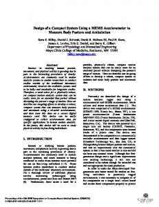
BIOGRAPHY
ABSTRACT
In this paper, we have implemented an experimental gyrocompass device based on a low-cost MicroElectro-Mechanical System (MEMS) gyroscope sensor. With the proposed system we have achieved an accuracy of approximately 1 with respect to the true North orientation. For achieving this level of accuracy, many relatively small errors needed to be accounted for and eliminated. In this paper, we describe the procedures used to compensate for these errors. The high level of Martti Kirkko-Jaakkola received his M.Sc. degree accuracy obtained in these experiments suggests in 2008 from Tampere University of Technology that new MEMS gyroscopes may be suitable for (TUT), Finland. He is currently working as a applications where, until recently, only more researcher at TUT; his research interests include expensive gyroscopes, e.g., ring laser gyros, have precise satellite positioning and low-cost navigation been used. systems. Keywords – MEMS gyroscope; gyrocompass; Jussi Collin is a research fellow at TUT. He bias compensation received his Dr. Tech. degree from TUT in 2006. His research interests are in statistical signal I. INTRODUCTION processing, specializing in sensor aided positioning Accurate orientation is a key factor in many location and navigation. systems and is typically obtained by using a digital magnetic compass (DMC). These devices are Jarmo Takala received his M.Sc. and Dr. Tech. compact low-cost instruments capable of achieving degrees from TUT, Finland in 1987 and 1999, a heading accuracy of several milliradians [1]. This respectively. Currently he is Professor at TUT and is suitable for applications such as targeting, his research interests include digital signal pointing and personal navigation. However, the processing and programmable parallel architectures heading accuracy of a DMC can be very easily for DSP. degraded by nearby ferrous materials or by electromagnetic interference. For these reasons, Corneliu Rusu received his PhD degree at DMCs are not very reliable inside buildings. In Technical University of Cluj-Napoca (TUCN) in 1996 contrast, inertial gyrocompasses can easily and his Doctor of Technology degree from Tampere overcome these problems and still maintain a high University of Technology (TUT) in 2000. Currently level of accuracy. These devices often use highhe is Professor at TUCN and his research interests quality (navigation-grade) gyroscopes for include signal reconstruction, adaptive filtering and determining the true North orientation. However, this computer aided analysis of and synthesis of circuits. technology is expensive, which makes it unpractical Lucian Ioan Iozan received his B.Sc. degree in 2008 from Technical University of Cluj-Napoca (TUCN), Romania, majoring in Electronics. Since 2008, he is studying towards M.Sc. degree and PhD studies in the Faculty of Electronics, Telecommunications and Information Technology at TUCN, majoring in Microelectronics and Electromagnetic Compatibility and also in sensor based location systems.
for most location systems that are on the market at weak signals requires precise error analysis and this time. Our goal was to implement a low-cost but filter design. A good measure for characterizing high-accuracy North finding system. these errors is the Allan variance. This paper describes a method for finding the North direction using a low-cost Micro-Electro-Mechanical System (MEMS) gyroscope. In long-term measurements, angular rate random walk and temperature variations are some of the errors that influence the bias instability of the sensor. Longterm measurement errors and temperature effects were reduced by frequently changing the sensor orientation. For this purpose, a step motor was used to switch between different orientations. Temperature effects were restricted by keeping the unit at room temperature and letting the sensor warm up prior to the experiments. Finally, an extended Kalman filter (EKF) was implemented for controlling the rotations of the turntable. In the last couple of years, several authors have reported progress in the development of highaccuracy MEMS gyroscopes with North seeking capabilities [2–4]. In [3, 4] the errors from the gyroscope sensor were compensated for by carouseling, so that the bias errors were almost entirely eliminated from the heading measurements. By using this compensation the accuracy of the gyrocompass increased considerably. In our approach we have used an extended Kalman filter combined with a sequence of rotations for compensating the main sources of errors that affect the measurement data of the gyroscope.
A. Allan variance The “Allan variance” was named after Dr. David Allan who worked out a method of characterizing noise and stability in clock systems [6]. It is a method which analyzes a time sequence and pulls out the intrinsic clock noise from a system, as a function of the averaging time. The Allan variance was developed for clocks, but it can easily be adapted for any other type of output [7]. The computation of Allan variance starts by taking a long sequence of data and dividing it into bins based on an averaging time . The Allan variance can be computed as
AVAR 2
1 2 n 1
y
i 1
y
2 i
(1)
i
where
AVAR 2
is the Allan variance as a function of the averaging time ;
yi
is the average value of the measurements in bin i ; is the total number of bins.
n
For short averaging times, the Allan variance is dominated by the uncorrelated noise in the sensor output. There is a direct correlation between the standard deviation of the output versus time with the slope of the Allan Variance at small [7]. In the beginning, the Allan Variance decreases as the The paper is organized as follows. At the beginning, averaging time gets longer; then, as the averaging the theoretical background of this paper is time increases, the Allan variance typically levels off presented. The measurement setup is described in due to 1 f noise [8]. The power of 1 f noise is Section 3 while Section 4 analyses the results of our commonly used to define the bias instability [9]; thus, research. Finally, we conclude in Section 5. the minimum value of Allan variance can be used as a measure of bias instability. II. THEORETICAL BACKGROUND This paper describes a method for determining the At some point, the Allan Variance starts to increase true North orientation, by measuring the magnitude again. This is due to bias drift or angular rate of the Earth’s rotation rate, which according to the random walk error in the sensor output, a process World Geodetic System 1984 (WGS84) is which is clearly non-stationary. The Allan variance is a very helpful tool in MEMS-based navigation error 7292115 10 11 rad s [5]. The input range of e analysis because 1 f and random walk noise a MEMS gyroscope is typically in the order components are typically very strong. For example, of 100 s while the magnitude of the signal that consider a problem where the gyroscope bias needs needs to be detected is approximately 0.004 s . to be estimated from the gyroscope output. As long Under these conditions it is clear that tracking such as the sensitivity axis of the gyroscope remains
aligned with the East-West direction, it is known that the actual input is zero. To estimate the bias, one can then obtain a sequence of measurements and take the average. This estimate of the constant bias is not necessarily the optimal estimate, as the error process is correlated in time [10], but is sufficient for our purpose. B. Measuring the Earth’s rotation rate As shown in [11], in order to measure the magnitude of the Earth’s rotation rate, the external factors that affect the output data of the gyroscope sensor must be carefully compensated for. One of these factors is the gravitational force which has a large effect over the gyroscope data. The solution for compensating this force came from fixing the sensitive axis of the gyroscope parallel to the local horizontal plane. By doing this, the g-sensitivity is the same in all the measurement positions and can be easily compensated for. Furthermore, to compensate for the gyroscope bias, the setup was rotated 180 after each measurement position. The measurement models are b bg cos (2) position e cos
measurements corresponding to (4). However, since the opposite angular rate measurements (2) and (3) cannot be made simultaneously, the gyroscope bias b may have changed between the measurements—particularly if the ambient temperature has changed. Therefore, we will have a bivariate state vector
x
(5)
b
where b denotes the change in gyroscope bias. We will model the offset angle as a constant with deterministic changes due to turntable rotations. In contrast, b is modelled as random walk plus linear correlation with the ambient temperature; in our tests, we used the empirical temperature coefficient 8°/(h K). Our measurements are the differenced angular rate (4) and the average sensor temperature difference between the measurements, yielding the Jacobian matrix
H
sin
~ e
0
cos
1 3600 / 8
.
(6)
It should be noted that the offset angle obtained using (2) and (3) has a 180° ambiguity. Thus, the (3) position 180 quadrant of must be resolved when the initial where b is the gyro bias, is the latitude, and bg is state vector and covariance are determined for the the g-sensitivity which is taken into account as an EKF. This can be done, e.g., by rotating 360° at a unknown but constant term. denotes the angle certain spacing and fitting a sine curve on the between the sensing axis and North direction; for measurements. example, when the sensing axis is parallel to the East—West direction, Earth rotation is not sensed at III. MEASUREMENT SETUP all. For each measurement orientation, the ~ magnitude of the Earth’s rotation rate e can be As the gyroscope, we used a prototype version of the SCC1300-D02 MEMS sensor [13]. The package estimated using (2) and (3) as follows: of the sensor is depicted in Figure 1, while the ~ position position 180 (4) experimental setup is shown in Figure 2. cos cos
b
cos e cos
e
bg
2
Now, if the latitude and Earth rate are known, the offset angle can be estimated, enabling seeking the North direction based on gyro measurements only by means of Kalman filtering. C. Extended Kalman filtering The EKF solves the state-space filtering problem where the state transition and measurement functions are nonlinear but measurement noise is zero-mean white Gaussian [12]. In this work, we apply the EKF for estimating the offset angle from
Figure 1. The SCC1300-D02 sensor package.
Figure 2. Measurement setup used for finding the true North orientation.
Our test setup consisted of the following hardware: SCC1300-D02
SPI interface
Turntable
Voltage regulator
Power supply
Hewlett-Packard E3611A, DC power supply, 0-20 V and 1.5 A; A laptop was used for reading (and saving) the data from the SCC1300-D02 sensor and for controlling the turntable.
A combined 3-axis accelerometer and a singleLaptop axis gyroscope sensor with an SPI interface for transferring the data. The sensor was manufactured by VTI Technologies and released at the beginning of this year [13]; A block diagram depicting the connections between We used the National the system’s main components is presented in Instruments NI-8451 USB Figure 3. device that provides I2C, SMBus and SPI communication interfaces with 8 chip select lines [14]; A Velmex B5990TS turntable was used to position the sensor in different orientations throughout the measurements; This component was selfmanufactured. It stabilizes the input voltage at 5V & 3.3V dc; Figure 3. Block diagram of the measurement setup.
TABLE I. GYROSCOPE SENSOR SPECIFICATIONS [13] Parameter Operating range Noise (RMS) Sensitivity Offset short term instability Quantization SPI clock rate
Typical values ± 100 /s 0,06 /s 50 LSB/( /s) < 1 /h 0,05 /s 0,1 – 8 MHz
Table I summarizes the technical specifications of the gyroscope sensor. It can be seen that the resolution of the gyroscope meets the requirements for measuring the Earth’s rotation. However, it has been shown that if the errors that affect the output data of the gyroscope sensor are properly compensated for, it is possible to estimate the angular rate using enough samples and still achieve a high accuracy level in detecting the Earth’s rotation rate [11]. Based on these results, we are confident that our North finding system can determine the true North orientation with a high accuracy.
instability. The raw data collected in the experiment is presented as a function of time in Figure 4, while the corresponding Allan variance plot is presented in Figure 5.
Figure 4. Raw data as a function of time.
IV. EXPERIMENTAL RESULTS All the measurements from this paper were conducted in Tampere (Finland) at latitude 61 .44 N . Throughout these experiments, the sampling frequency of the gyroscope sensor was approximately 1 kHz, determined by the NI–8451 USB device which was the slowest device in the setup. If a higher sampling rate is required, another device that has an SPI hardware which supports 16/32 bit transfer must be used. For processing the gyroscope data and also for controlling the turntable rotations we used the MATLAB R2008a software. Figure 5. Allan deviation of the gyroscope sensor.
A. Bias instability of the gyroscope sensor Bias instability is a major source of errors in the output data of the gyroscope sensor. In order to properly compensate for these errors, we need to determine their effect on the gyroscope data. For this purpose we have collected a long sequence of data with the sensor fixed on floor level. During the measurement, the sensitive axis of the gyroscope sensor was parallel to the local horizontal plane. The entire experiment spanned approximately 61 hours. Despite the fact that the test was performed in an office environment where natural temperature fluctuations can possibly cause some deterioration of the measurements, we expect that the experiment will yield at least a rough estimate of the bias
From the Allan variance plot it can be seen that the bias instability is approximately 0.00034 /s, which equals about 1.2 /h. In conclusion, the noise level of the new SCC1300-D02 gyroscope sensor is low enough to theoretically measure the angular velocity of the Earth, making it possible to find the true North direction. B. North finding system Our work from [11] represented the starting point in the development of this MEMS gyro compassing system. Basically, for determining the North direction, the system needs to measure the magnitude of the Earth’s rotation rate with high
accuracy. In order to do that, many relatively small errors need to be accounted for and eliminated. One of these errors is the g-sensitivity which was compensated by fixing the sensitive axis of the gyroscope parallel with the local horizontal plane, as shown in Section 2. However, since the latitude of our measurement location is 61.44 N , only half of the Earth’s rotation rate can be detected by the gyroscope sensor. Even so, the magnitude of the remaining rotation rate can be measured without problems [11]. Figure 2 shows the experimental setup used for finding the true North orientation as described in Section 3. For the first experiment conducted with our North finding system, we decided to collect a set of measurements for a 450 rotation of the turntable. The experiment lasted approximately 7.5 hours, and it consisted in 45 measurement positions. Each position was sampled for approximately 10 minutes. The purpose of this experiment was to determine which orientation (North, South, East or West) is the most suitable to be detected. The results are presented in Figure 6.
slope of the measurement is steeper, making the detection process more accurate. Based on this result we have implemented a control loop for the Velmex turntable. The algorithm consists in two steps. First the magnitude of the Earth’s rotation rate is measured according to Equation (4). Then, based on the computed value, the control loop rotates the measurement setup towards East or West. The process is repeated 30 times. Figure 7 presents three separate measurement sequences.
Figure 6. 450° rotation spaced by 10° with ten minutes of sampling at each measurement position.
For each measurement position, the last 5 minutes of data ( position 180 ) were collected after the experimental setup was rotated with 180 . This was done in order to compensate for the bias and the effect of the gravitational force from the first 5 minutes of data ( position ). Finally, each point from the graphic was obtained according to Equation (4), representing the average value of one measurement Figure 7. The results obtained by using deterministic control position. The result obtained in Figure 6 shows that sequences. In a), b) and c) the setup was at 90 from reaching East. East and West directions are easier to be detect than North and South. This is due to the fact that the From Figure 7 it can be seen that the estimation error varies between ±7 from reaching the East
direction. Furthermore, the time needed for the system to converge to one of these directions (East or West) is high. Basically, these drawbacks are caused by the fact that the control loop is using only the current measurement data for determining the next angle of rotation. So, for our next measurements we decided to use an extended Kalman filter as described in Section 2. For testing the filter we used the same data as in Figure 6. Figure 8 presents the response of the filter according to the input data.
Figure 8. Kalman filter response to the training data.
As it can be seen from Figure 8, the output of the filter is almost overlapping the theoretical values of the Earth’s rotation rate. Based on this result we decided to modify the control loop to include the proposed filter. Figure 9 and Figure 10 shows the results obtained using the new implementation.
Figure 10. Both results were obtained using the same EKF. In i) the setup was at 90 from reaching East while in ii) the setup was at 60 from reaching the same orientation.
From these measurements (see Figure 9 and Figure 10) it can be seen that the accuracy of the system was improved by using the Kalman filter approach. For example, in Figure 9 after approximately 2 hours the system reaches East direction for several times while in the last measurement position it stops at 0.9 from the same orientation. Finally, after one of the two directions (East or West) is known, then is quite simple to determine the true North orientation. V. CONCLUSIONS
Figure 9. The result was obtained by using the proposed EKF while the measurement setup was at 90 from reaching East.
This paper presents the hardware implementation of a low-cost North finding system and some experimental results. The main contributions consist in compensating the non-stationary bias errors via a sequence of rotations and also in implementing a control loop for the turntable using an extended Kalman filter. The Kalman filter approach improved the accuracy and reduced the convergence time
Defense World Geodetic System 1984, Its when compared to deterministic control sequences. definition and relationships with local geodetic With the proposed system we achieved an accuracy of approximately 1 with respect to the true North systems”, 3rd ed. orientation. Future work will be focused on [6] D. W. Allan. The Allan variance [web page on decreasing the time needed for the system to reach the Internet], URL: http://www.allanstime.com the North direction and also on integrating the /AllanVariance/index.html [updated 2004 Feb proposed setup in a real navigation system. 07; cited 2010 Jul 01]. [7] Crossbow Technology. “Bias Stability Measurement: Allan Variance”. URL: http://www. ACKNOWLEDGMENT xbow.com/support/Support_pdf_files/Bias_Stabil The authors are thankful to VTI Technologies for ity_Measurement.pdf [cited 2010 Jul 01]. providing the samples of the new SCC1300-D02 [8] R. VOSS, “1/f (flicker) noise: A brief review”, MEMS-gyroscope. Proceedings of the 33rd Annual Symposium on Frequency Control, 1979. REFERENCES [9] IEEE Standard for Inertial Sensor Terminology, IEEE Std 528-2001. URL: http://ieeexplore.ieee. [1] Datasheet for Honeywell Point HMR3600 org/Xplore/guesthome.jsp digital magnetic compass, URL: http://www.ssec .honeywell.com/magnetic/datasheets/HMR3600. [10] Jan Beran, “Statistics for Long-Memory pdf, August, 2006. Processes”, ISBN 0-412-04901-5, 1994. [2] D. Lapadatu, B. Blixhavn, R. Holm, T. Kvisteroy, [11] L. I. Iozan, J. Collin, O. Pekkalin, J. Hautamäki, “SAR500 - A High-Precision High-Stability J. Takala, C. Rusu, „Measuring the Earth’s Butterfly Gyroscope with North Seeking Rotation Rate Using a Low-Cost MEMS Capability,” IEEE/ION Position Location and Gyroscope“, Symposium Gyro Technology Navigation Symposium, Palm Springs, CA, May 2010, Karlsruhe, Germany, September 2010. 3-6, 2010. [12] M. S. Grewal and A. P. Andrews. Kalman [3] Burgess R. Johnson, Eugen Cabuz, Howard B. filtering: theory and practice. Prentice Hall, French, Ryan Supino, “Development of a MEMS 1993. Gyroscope for North finding Applications”, [13] VTI Technologies. Data sheet, “SCC1300–D02 IEEE/ION Position Location and Navigation combined gyroscope and 3-axis accelerometer Symposium, Palm Springs, CA, May 3-6, 2010. with digital SPI interfaces”, Rev. 1.0, Doc. Nr. 82 [4] B. M. Renkoski, “The effect of carouseling on 1130 00 A. URL: http://www. MEMS IMU performance for gyrocompassing vti.fi/midcom-serveattachmentguid9b979204cde applications,” Thesis (S.M.), Massachusetts c11deae646bd1612964dc64dc/scc1300_d02_ Institute of Technology, Dept. of Aeronautics datasheet_v1.0.pdf and Astronautics, June 2008. [14] NI USB – 8451 device from National [5] National Imagery and Mapping Agency. Instruments. URL: http://sine.ni.com/psp/app/ Technical Report TR8350.2, “Department of doc/p/id/psp-318/lang/en