INTERNATIONAL JOURNAL OF INNOVATIVE RESEARCH EXPLORER ISSN NO: 2347-6060
Numerical Investigation on behavior of cold formed built up steel columns S.Vigneshkannan1, J.Abdul Bari2 1
P.G Student, Department of Civil Engineering, K.S.Rangasamy College of Technology, Tiruchengode-637211. Associate Professor, Department of Civil Engineering, K.S.Rangasamy College of Technology, Tiruchengode-637211.
2
[email protected] [email protected]
Abstract— The modern construction world to be satisfied in two different categories are economic and serviceability. This paper discuss about the load carrying capacity and design of cold formed built up steel sections by numerical (Indian Standard and Direct Strength) methods. A total of eight compressive specimens (short and long built up steel column sections) were fabricated which is pinned end condition and are connected front to front with web intermediate stiffener to form built up column sections. The material properties are determined by conducting the coupon test. The chosen cross section profiles are satisfied with all possible mode of failure under the axial compression elements. The section properties were arrived from the CUFSM. Finally, the load carrying capacity was evaluated by using numerical methods and they are compared with each other. Keywords— cold formed built up steel sections, web intermediate stiffener, load carrying capacity, pinned end condition, short and long column.
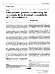
I. INTRODUCTION Cold formed steel is basically the opposite of hot formed, or better, hot-rolled steel in terms of method of production. Hotrolled steel is prepared by pressing steel into thin sheets under tremendous pressure and very high temperatures, cold-formed steel happens to be produced at relatively colder temperature, rolled or pressed, mostly at the room temperature of the production area. Cold rolled steel is generally used for the manufacturing of appliances, structural members, automobiles, etc. One of the biggest advantages of cold formed steel over normal structural steel is that it can be molded into a huge variety of shapes without significantly affecting its strength, unlike that of hot-rolled steel. Though being slightly less ductile than its counterpart, cold formed steel is quite cheaper and light in weight, thus making it easier to deal with at construction sites. The Direct Strength Method (DSM), adopted by American Iron and Steel Institute (AISI) as an alternative design procedure (NAS 2004), uses the entire cross-section in the elastic buckling determination and offers specific provisions for local, distortional and global buckling strength without effective width calculations and iteration. However, DSM, regarded as the next generation design method, is still under development towards a comprehensive design procedure. Furthermore advanced numerical analysis tools such as finite strip or finite element software are generally required for determining the elastic buckling behavior of crosssections. The effective width concept based design procedures of NAS (2001) is still widely utilized by today’s engineers.(Cheng Yu and Trevor Lokie,2006).The cross section of the light gauge steel members varies with its application. The theoretical investigations of channel section have high bending strength, high load caring capacity, minimum deflection and minimum local buckling & distortional buckling compare to the built up channel section by same cross sectional area.(Jayaraman et al, 2015) The design of Cold – Formed steel section is done by using I.S. 801-1975. This results in uneconomic design because in W.S.M. full section is not utilized. So to utilize the full cross – section of the section and to maintain economy, it is required to revise Indian Standard Code and also in S.I. System.(Kakade et al, 2014) The construction field to be going on facing the building materials (such as Fine aggregate, binder materials, etc.,) demand condition. So, the alternative solution can be adopted for usage steel structure construction. The compression member can accompanying a major role in the building. This paper study the cold formed built up compression member, because it carrying the high strength, high load carrying capacity, minimum buckling. This study shows that determination of the load carrying capacity of two methods (Indian Standard and Direct Strength methods) then compared the results of them. II. MATERIAL PROPERTY The material properties of the test specimen are determined by tensile coupon test (Fig 1 (a) and (b)).Tensile coupons are formed and tested according to IS 1608 – 5, determine the parameters are yield stress, ultimate stress, young’s modulus and percentage of elongation as shown in Table I.
VOLUME 5, ISSUE 4, APRIL/2018
16
http://ijire.org/
INTERNATIONAL JOURNAL OF INNOVATIVE RESEARCH EXPLORER ISSN NO: 2347-6060
TABLE I TEST RESULTS FOR COUPON TENSILE TEST
Sl.N o.
Yield Stress (N/mm2)
1
275
Young’s Modulus (N/mm2)
Ultimate Stress (N/mm2)
2.02x10⁵
All dimensions are in “mm”. Test sample
345
Elongation (%)
12.5
Test set up (b)
(a) Fig. 1 Coupon Test
150
III. SECTION PROFILE All Details of specimens and physical properties of the section are discussed in this chapter. All the specimen are designed from 1.5 mm thick cold-rolled sheets. To minimize the local buckling and distortional buckling for all the specimens are arrived based on the North American Specification for cold-formed steel section. The selected cross section profiles and dimension are shown in Figure 2 (a) USC (Uniform Steel Section), (b) SC-V (Steel Section with V Stiffener, (c) SC-U (Steel Section with U Stiffener) and (d) SC-∑ - Steel Section with ∑ Stiffener.
(a) USC
(b) SC V
(c) SC U
(d) SC ∑
Fig.2 Section Geometries with Dimensions
IV. SECTION PROPERTY The built up column sectional properties of cold formed steel section (given in Table II). Thus the properties are arrived from using CUFSM software.
VOLUME 5, ISSUE 4, APRIL/2018
17
http://ijire.org/
INTERNATIONAL JOURNAL OF INNOVATIVE RESEARCH EXPLORER ISSN NO: 2347-6060 TABLE III SECTIONAL PROPERTIES FOR SELECTED SECTIONS
Description / Specimen ID Area, A in (mm) Sectional modulus, Z in (mm3) Moment of inertia xx direction, IXX in (mm4) Radius of gyration, r in (mm)
USC 907.6
SC V 907.6
SC U 907.6
SC ∑ 907.6
152.25
150.32
149.76
145.24
3.494 x 10⁶ 62.05
3.514 x 10⁶ 63.56
3.598 x 10⁶ 64.13
4.015 x 10⁶ 65.20
V. NUMERICAL EVALUATION A. Indian Standard (I.S) Method Based on the specification Indian Standard (IS) Method for cold formed steel design, the capacity of member in axial compression (PIS). The load carrying capacity for long and short built up column by indian standard method (as given in Table III). Effective width: 𝑓 = 0.6𝑓𝑦 = 165 N/mm2
Basic compressive strength,
𝑤
478
𝑡
√𝑓
( )lim =
= 63.98
𝑤
( ) = 94.67 > 63.98 𝑡
𝑏 658 130 = [1 − 𝑤 ] 𝑡 √𝑓 ( ) √𝑓 𝑡 𝑏 = 45.75 𝑡 b = 45.75 X 1.5 = 68.63mm Aeff = 419.38mm2
Effective area: Form factor:
Q=
𝐴𝑒𝑓𝑓 𝐴
= 0.462
Slenderness Ratio: 𝐿
𝐶𝑐
𝑟
√𝑄
( )lim =
= 177.16
𝐿
Actual ( ) = 18.05 < 177.16 𝑟
Allowable stress and load: 𝑓𝑎𝑙 =
12 3 𝑄𝑓𝑦 2 𝑘𝑙 2 𝑄𝑓𝑦 − ( 2 ) (( ) ) 23 23 𝜋 𝐸 𝑟 𝑓𝑎𝑙 = 66.02 N/mm2 𝑓𝑎
VOLUME 5, ISSUE 4, APRIL/2018
= 60.1 kN
18
http://ijire.org/
INTERNATIONAL JOURNAL OF INNOVATIVE RESEARCH EXPLORER ISSN NO: 2347-6060 TABLE IIIII LOAD CARRYING CAPACITY RESULTS BY I.S METHOD
Sl.No.
1 2 3 4
Specimen ID
Load carrying capacity (kN) Short built up long built up steel steel column column section
USC SC- V SC-U SC-∑
60.1 85.24 96.35 104.23
48.55 69.76 80.48 87.44
B. Direct Strength Method Based on the specification Direct Strength Method (DSM) for cold formed steel design , the capacity of member in axial compression (Pn.DSM) shall be minimum of local buckling (Pnl), distorsional buckling (Pnd) and flexural torsional buckling(P ne). The load carrying capacity for long and short built up column by direct strength method (as given in Table IV). (0.658)λ𝑐 2 𝑃𝑦 , for λc ≤ 1.50 Pne = { 0.877 Pne = 89.93kN ( ) 𝑃𝑦 , for λc > 1.50 𝜆𝑐2 Py = Afy, Py is a squash load 𝛌c = √
𝑃𝑦 𝑃𝑐𝑟𝑐
The nominal axial strength (Pnl) for local buckling, 𝑃𝑛𝑒 , for λ1 ≤ 0.776 Pnl = { Pnl = 89.02kN Pcrd Pcrl (1 - 0.15( )^0.6 ( )^0.6) Py, for λ1 > 0.776 𝑃𝑛𝑒
𝑃𝑛𝑒
𝛌1 = √
𝑃𝑛𝑒 𝑃𝑐𝑟𝑙
The nominal axial strength (Pnd) for distorsional buckling, 𝑃𝑦 , for λd ≤ 0.561 Pnd = { Pnd = 88.73kN Pcrd Pcrd (1 - 0.25( )^0.6 ( )^0.6) Py, for λd > 0.561 𝑃𝑦
𝑃𝑦
𝛌1 = √
𝑃𝑦 𝑃𝑐𝑟𝑑
Whichever is lesser, i.e., Axial Strength, (Pn.DSM) = 88.73kN TABLE IVV LOAD CARRYING CAPACITY RESULTS BY I.S METHOD
Sl.No.
1 2 3 4
Specimen ID
USC SC- V SC-U SC-∑
Load carrying capacity (kN) Short built up steel long built up steel column column section
88.73 98.46 125.12 146.88
57.09 75.76 91.48 100.44
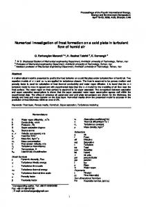
VI. RESULTS AND DISCUSSION A. Indian Standard Method Results From the Indian Standard method used to obtained the load carrying capacity values are short built up steel columns and long built up steel column sections (shows that Fig 3) for selected four different specimen ID respectively. I.S 801:1975 codal provisions refer to resolve this method.
VOLUME 5, ISSUE 4, APRIL/2018
19
http://ijire.org/
INTERNATIONAL JOURNAL OF INNOVATIVE RESEARCH EXPLORER ISSN NO: 2347-6060
LOAd (kN)
load carrying capacity 160 140 120 100 80 60 40 20 0
Load carrying capacity (kN) Short Column Load carrying capacity (kN) long Column USC SC- V SC-U SC-∑ Specimen ID
Fig. 3 load carrying capacity by I.S method
B. Direct Strength Method Results From the Direct Strength method used to obtained the load carrying capacity values are short built up steel columns and long built up steel column sections (shows that Fig 4) for selected four different specimen ID respectively. From CUFSM software results in modification factor value taken as input value for this method. Load carrying capacity 120
load (kn)
100 Load carrying capacity (kN) Short Column
80 60 40 20 0 USC SC- V SC-U SC-∑
Load carrying capacity (kN) long Column
specimen Id Fig. 4 load carrying capacity by Direct Strength method
C. Discussion The theoretical results are compared with Indian standard and direct strength method for short built up steel columns (Fig 5) and long built up steel column sections (Fig 6) respectively. In order to determined load values gradual increased direct strength method. 300 load carrying capacity for short column
Load (kN)
250
load carrying capacity for short column(kN) By Direct Strength method
200 150 100 50 0 USC
SC- V
SC-U
SC-∑
Specimen ID
load carrying capacity for short column(kN) By Indian Standard method
Fig. 5 comparison load results for short built up steel column
VOLUME 5, ISSUE 4, APRIL/2018
20
http://ijire.org/
load (kn)
INTERNATIONAL JOURNAL OF INNOVATIVE RESEARCH EXPLORER ISSN NO: 2347-6060
200 180 160 140 120 100 80 60 40 20 0
load carrying capacity for long column load carrying capacity for long column(kN) By Direct Strength method
USC
SC- V
SC-U
SC-∑
load carrying capacity for long column(kN) By Indian Standard method
specimen ID Fig. 6 comparison load results for long built up steel column
VII. CONCLUSIONS The numerical investigation of load carrying capacity for short built up steel column section and long built up steel column section to done by two methods (Indian standards and Direct strength methods). The material properties are determined by conducting a coupon test. The section properties can be evaluated with the help of CUFSM. The selected section profile can be optimized by using CUFSM. Thus the modification factor results were given the input for a direct strength method by obtain a load carrying capacity. Comparison of Indian standard method is 25% higher than short built up steel column section and 12% higher than long built up steel column section in direct strength method. REFERENCES [1] [2] [3] [4] [5] [6] [7]
[8]
A Jayaraman, V Senthilkumar and S Athibaranan3 (2014) “Behaviour and Design of Light gauge Cold Formed Steel Flexural Members (Comparison of Channel and Built up Channel Section)” International Journal of Scientific Engineering and Technology Research,Vol.03,Issue.19, pp.3941-3946. B. C. Punmia, A. K. Jain, and A. K. Jain, “Comprehensive Design of Steel Structures”, 2nd ed., 2008, Laxmi, New Delhi. Cheng Yu and Trevor Lokie (2006) “Effective Width Method Based Design for Distortional Buckling”, International Specialty Conference on ColdFormed Steel Structures, Orlando, Florida, U.S.A.pp.105-118. I.S. 801: 1975, “Indian Standard Code of Practice for Use of Cold-Formed Light Gauge Steel Structural Members in General Building Construction”, Bureau of Indian Standards, New Delhi. India. I.S. 811: 1987, “Indian Standard Specification for Cold- Formed Light Gauge Structural Steel Sections”, Bureau of Indian Standards, New Delhi. India. M. Meiyalagan , M.Anbarasu and Dr.S.Sukumar.(2010) “Investigation on Cold formed C section Long built up steel column section with Intermediate Stiffener & Corner Lips – Under Axial Compression.” International journal of applied engineering research, dindigul , Vol.1, No1,pp.122-129. R.B. Kulkarni and Shweta B.Khidrapure (2014) “Parametric study and comparison of Indian standard code with British standard code for the Design of Light gauge cold formed flexural members”,International Journal of Engineering and Technical Research (IJETR) ISSN: 2321-0869, Vol.-2, Issue-11, pp.325-332. S.A.Kakade, B.A.Bhandarkar, S.K. Sonar, A.D.Samare “ Study of various design methods for cold – formed light gauge steel sections for compresive strength” International Journal of Research in Engineering and Technology eISSN: 2319-1163, Vol.03, Special Issue: 09,pp.10-13.
VOLUME 5, ISSUE 4, APRIL/2018
21
http://ijire.org/