loadings [Aouameur, 1998, 1999]. The determination of the dynamic response is
made using the general finite element code CESAR-LCPC. This code allows to ...
0338
NON-LINEAR SEISMIC RESPONSE OF A RC BUILDING MOCK-UP: NUMERICAL MODELLING BY MULTILAYERED SHELL ELEMENTS Amel AOUAMEUR1, Jean-François SEMBLAT2 And Franz-Josef ULM3
SUMMARY The main purpose of this paper is the numerical analysis of the non-linear seismic response of a RC building mock-up. This study was part of the CAMUS International Benchmark. The mock-up is subjected to different synthetic horizontal seismic excitations. The model is only built considering both geometrical and mechanical features (determined from laboratory tests on concrete specimens) as well as the first three eigenmodes of the structure (estimated from low level random excitation). The numerical approach is based on a 3D-model involving multilayered shell elements. These elements are composed of several single-layer membranes with various eccentricities. Bending effects are included through these eccentricities. Basic equations are first written for a single membrane element with its own eccentricity and then generalised to the multilayered shell element by superposition (according to specific assumptions). There are many links between local and global scales. The multilayered shell is considered as a classical shell element : all informations about non-linear constitutive relations are investigated at the local scale of each layer, whereas balance and kinematics are checked afterwards at global scale. The non-linear dynamic response of the building is computed with Newmark algorithm. The numerical dynamic results are compared in the linear and non linear cases. Multilayered shell elements are found to be a promising tool for predictive computations of RC structures behaviour under 3D seismic loadings. INTRODUCTION The CAMUS international benchmark is a project aimed at comparing and validating the numerical tools commonly used for the load bearing walls. This project was supported by the Commissariat à l’Energie Atomique (CEA), Fédération Nationale du Bâtiment (FNB), Plan Génie Civil and Electicité De France (EDF). The experimental program took place in the CEA facilities in Saclay (France) and 11 international teams (Canada, Europe, Japan, USA) participated to the numerical benchmark [CEA, 1997, CEA, 1998]. A reducedscale model of the structure was considered and tested on the Azalée shaking table [Semblat, 1999]. In this study, the modelling and analysis of CAMUS structure are considered [CEA, 1997]. A three-dimensional model, based on a mutilayered shell element formulation, is used. This formulation allows to take into account material and geometrical non linear effects in the structural analysis of shell structures subject to various loadings [Aouameur, 1998, 1999]. The determination of the dynamic response is made using the general finite element code CESAR-LCPC. This code allows to model the behaviour of civil engineering structures. It includes a large library of constitutive laws and makes it possible to simulate many types of problems (linear, non linear, 2D, 3D, static, dynamic...). The linear response of the structure is firstly obtained using the modal superposition method. This response is compared to the one obtained in the non linear case using the multilayered shell element. 1 2 3
Eng. Modelling Dept, Laboratoire Central des Ponts et Chaussées, Paris, France Eng. Modelling Dept, Laboratoire Central des Ponts et Chaussées, Paris, France Massachusetts Institut of Technology, Cambridge, USA
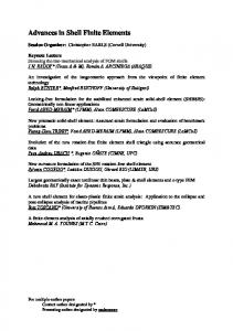
MULTILAYERED FINITE SHELL ELEMENT FORMULATION The multilayered shell element developed is composed of several single-layer membranes with various eccentricities and thicknesses (figure 1). Bending effects are included through these eccentricities. There are many links between local and global scales. All information about non-linear constitutive relations are investigated at the local scale of each layer, whereas balance and kinematics are checked afterwards at global scale.
Figure 1. Multilayered finite shell element. The main idea consists in establishing basic equations for a single membrane element with its own eccentricity and behaviour. These equations are then generalised to the multilayered shell element by superposition, according to specific assumptions.
� any vectorial fields of displacement and rotation, we make the assumption of small � and Ω Denoting U 0 0 perturbations. The local dynamic equilibrium, expressed as force and moment, of a shell of thickness h moved away from the reference surface S is leading to the following equations [Aouameur, 1998, 1999] :
(
)
∂ (BNα ) ∂ ( ANβ ) �� = 0 �� - ρ e h Ω + + AB q − ρ h U 0 0 ∂α ∂β
(1)
(
)
∂ ( B Mα ) ∂ ( A Mβ ) �� − ρ e h U �� = 0 + + AB n α ∧ Nα + nβ ∧ Nβ + m − I . Ω 0 0 ∂α ∂β
(2)
where q and m are respectively the force and moment applied by surface unit; nD and nE the local basis vectors of the shell; ND, NE, MD and ME the normal forces and global moments by length unit; U and e the mass density and eccentricity of the shell; A and B the Lamé parameters and I the dynamic moment of inertia defined by : I =
e+h /2
∫
ρ ζ 2 dζ .
e-h /2
Considering a material point Q at distance ] from the reference surface of the shell and P its orthogonal projection on this surface. Denoting no the normal to the mean surface, the position vector PQ can be expressed as PQ = e no. Assuming a constant stress state in the section of the moved single-layer shell, the generalized forces at point P are written as functions of the curvature radii of the shell, RD and R E, and of the stress tensor at point Q : eh N = ( σ. n ) h + R α
α
β
eh N = ( σ. n ) h + R β
α
h + 12 e M = n ∧ ( σ . n ) e h + 12 R 3
α
0
(3)
β
α
β
2
h
h + 12 e h M = n ∧ (σ . n ) e h + 12 R 3
β
0
2
β
(4)
α
2
0338
� (respectively), and after integration by parts of the result on S, � and Ω Multiplying equations (1) and (2) by U we obtain the weak formulation of the dynamic balance equations, (1) and (2), of a moved single-layer shell : 0
� � , ∀Ω ∀U 0
� � � � ∂U ∂U ∂Ω ∂Ω dS − ∫ A N . dS − ∫ B M . dS − ∫ A M . dS ∂α ∂β ∂α ∂β
− ∫ BN .
0
α
0
0
0
β
S
(
0
0
α
S
β
S
)
S
� dS + AB q . U� + m . Ω � dS + ∫ AB n ∧ N + n ∧ N . Ω ∫ S
α
α
β
β
0
0
0
(5)
S
�� . Ω � + ρe h U � + ρe hΩ �� . U� dS = 0 �� . U � +IΩ �� . Ω − ∫ AB ρ h U 0
0
0
0
0
0
0
0
S
This formulation is generalized to the multilayer case by superposition of n moved single-layer shells (compatibility of the shells displacements at global scale). For a multilayer shell element, this allows us to write the following incremental balance matricial equation : [M ]{�� ξ }+ n
∑ [K(C )] ep
k
k =1 , n
{∆ξ } = {F } − n
ext
∑ {F (σ )}
k =1 , n
int
(6)
k
where {∆ξn} is the vector of nodal parameters increase at the considered iteration. Equation (6) raises the need for the computation of the tangent stiffness matrix as well as the internal forces vector for all the layers (k = 1, n). It leads to the following expression :
∑ [K(C )] ep
k =1 , n
k
=
∑ h ∫ [B] [C ] [B] dS t
k =1, n
k
k
Sk
ep
k
k
k
∑ {F (σ )}
k =1 , n
int
k
=
∑ h ∫ [B] {σ} dS t
k =1 , n
k
k
k
k
(7)
Sk
[B]k being the matrix of the derivatives of the interpolation functions linking the nodal displacement vector of the multilayer shell element to the components of local strain tensor for layer k. Shell theory allows the use of plane stress assumption for the multilayer shell. This assumption states that the stress normal to the reference surface of the shell is zero. It is then necessary to fulfil this assumption in every single layer of the multilayer shell. A particular treatment of equations (7a) and (7b) is needed for the computation of stresses as well as the tangent behaviour matrix [Cep] at the local scale of each layer. For the integration of stresses, ones considers a local iterative scheme [Ortiz, 1986] allowing the use of various constitutive laws with internal variables. Whatever the constitutive law is, the computation of stresses is performed the same way [Aouameur, 1998, 1999]. For the calculation of the elastoplastic behaviour tensor, a numerical method proposed by De Borst is adopted [De Borst, 1991].
SEISMIC RESPONSE OF CAMUS STRUCTURE Description of the model The structure considered for the international benchmark CAMUS is composed of two parallel R/C walls without opening, linked by 6 square floors (including the floor connected to the footing) [CEA, 1997]. A heavily reinforced concrete footing allows the anchorage to a shaking table. The walls are loaded in their own plane. The stiffness and the strength in the perpendicular direction are increased by adding some lateral triangular bracing. This system reduces the risk of failure which might be induced by some parasite transversal motion or a nonsymetric failure of the structural walls. igure 2 shows the meshing of the complete three-dimensional model (structure + shaking table + springs). It is mainly composed of multilayered shell elements, tridimensional block and beam elements. The boundary condition concerns the centre of gravity which is fixed in the horizontal direction to avoid the free body motion of the structure. The total mass of each floor is calculated considering the self weight of the floor and 6 additional masses (above and under the floor) [Semblat, 1999]. These masses have been determined in order to impose a normal force to the walls compatible with the vertical stress values commonly found at the base of such structures (i.e scale factors of the reduced scale model).
3
0338
Figure 2. Mesh of the complete three-dimensional model. Linear case. Eigenmodes and Eigenfrequencies Table I shows the results of the modal analysis obtained with the complete three-dimensional model. The first experimental frequency of the mock-up was measured before the first tests equal to 7.24 Hz, the second one to around 33 Hz (in-plane bending) and the first vertical eigenmode has a natural frequency equal to 20 Hz. These frequencies were measured applying a low level random excitation to the specimen. In the computation, we have considered different values of K (stiffness of the table vertical springs). The numerical results obtained are satisfactory and close to the experimental ones (table I). For the value of K=3.0 108 N/m, eigenfrequencies have a little discrepancy and the corresponding percentages of error are small (5.6, 2.1 and 0.07 %). For the following numerical investigations, we have chosen the value of K such as K=3.0 108 N/m. Table I. Eigenfrequencies for different values of K for the complete three-dimensional model Values of K (N/m)
1st eigen frequency f1 (Hz)
2nd eigen frequency f2 (Hz)
3rd eigen frequency f3 (Hz)
error % for f1
4.0 108
7.81
21.69
34.28
7.8 %
8.4 %
3.8 %
3.0 108
7.65
19.58
33.25
5.6 %
2.1 %
0.07 %
2.5 108
7.52
18.26
32.40
3.8 %
8.7 %
1.8 %
error % error % for f2 for f3
The three first eigenmodes of the complete three-dimensional model (structure + shaking table) are given in figure 3. The first eigenmode corresponds to in-plane bending, the second one to pure vertical motion and the third one to another in-plane bending mode.
4
0338
Figure 3. Three first eigenmodes for the complete three-dimensional model.
Linear dynamic response of the structure The determination of the linear dynamic response of the structure is made using the modal superposition method. Two different acceleration signals are considered : CAMUS17 and CAMUS19. These signals are depicted in figure 4 and correspond to the horizontal acceleration applied to the shaking table. The loading of the structure is then equivalent to a rigid base motion. To apply this kind of excitation to the structure, we have considered a volumic density of force in the horizontal direction having the same variations in time than the applied acceleration. Inertial forces are then directly involved in the computation giving the response to horizontal rigid base motion. For the computation, 1200 time steps of ∆ t = 0.01 s are considered.
Figure 4. Acceleration signals CAMUS17 and 19. Different values of K were used for the computation [CEA, 1998]. After studing the graphs, we observed that the maximum displacement reached, depended on the corresponding K value. For the present computation, we have chosen K = 3.0 108 N/m. Figure 5 gives the horizontal displacement at the top of the structure obtained by modal superposition for the two acceleration signals : CAMUS17 and 19. It can be seen that this displacement increases with the signal magnitude. In fact, for CAMUS17, the maximum displacement is about 1.2 cm, whereas for CAMUS19, it is worth 5 cm. When considering the effective modal masses, two modes are mainly contributing to the dynamic response of the structure : the first and the third ones [Semblat, 1999].
5
0338
Figure 5. Horizontal top displacement of the structure (CAMUS17 and 19) for K=3.0 108N/m. Linear case.
Non linear dynamic response of the structure Figure 6 shows the meshing of the three-dimensional model used in the non linear analysis. It is composed of multilayered shell elements, tridimensional block and beam elements. Because of the symmetry, half of the structure is modelled. The same loadings which have been described in paragraph 3.3 (CAMUS17 and 19) are considered. A macroscopic model (the Willam-Warnke model with 3 parameters) coupling plasticity with damage is used for modelling the non-linear behaviour of concrete [Willam, 1973, Ulm, 1994]. For the computation, 6000 time steps of ∆ t = 0.002 s are considered.
Figure 6. Mesh of the complete three-dimensional model. Non linear case. Figure 7 gives the horizontal displacement at the top of the structure for the two acceleration signals : CAMUS17 and 19. The non linear dynamic response obtained is compared to the linear one [Semblat, 1999]. These responses coincide during the first time steps and there is afterwards a large discrepancy between the two responses when non linear effects due to concrete cracking appear. It shows the influence of local damage on the dynamic response of the whole structure. It leads to an increase of the period of vibration of the structure, that is a frequency drop [Ulm, 1993]. Figure 8 gives the plastic strain isovalues at time t = 11 s for the two acceleration signals : CAMUS17 and 19. These isovalues shows the increase of plastic strains with the signal magnitude. For the strongest accelerogram CAMUS19, the three first levels show high plastic damaging.
6
0338
Figure 7. Horizontal top displacement - linear and non-linear cases (CAMUS17 and 19). Non linear case.
Figure 8. Plastic strains at t=11s (CAMUS17 and 19).
CONCLUSION In the CAMUS project, the seismic response of a building was studied through shaking table tests on a reducedscale model [CEA, 1997]. The contribution of the LCPC to the numerical benchmark of the project has been made thanks to the finite element code CESAR-LCPC. Numerical results obtained in both linear and non linear cases clearly show the efficiency and accuracy of the proposed multilayered shell element formulation. This formulation allows the computation of the non linear dynamic response of complex three-dimensional structures under severe seismic loadings. Furthermore it is made in a general frame and one can choose any constitutive law for the different materials [Aouameur, 1998, 1999]. Comparisons between the numerical results obtained by the different participants were proposed by the CEA [CEA, 1998]. Detailed numerical results are also given in [Ragueneau, 1998 & 1999, Ile, 1998].
7
0338
REFERENCES Aouameur A. (1998), Non linear material and geometrical analysis of RC shell structures under static and dynamic loadings, Ph.D. thesis, ENPC, Paris. Aouameur A., Ulm F.J., Humbert P., Semblat J.F. (1999), Analyse non linéaire de structures par éléments finis de coque multicouche, Revue Française de Génie Civil, 3(5), 20 pages. CEA (1997), Mock-up and loading characteristics. Specifications for the participants report, « Camus » International Benchmark. CEA (1998), Synthesis of the participants reports, « Camus » International Workshop, 11th European Conference on Earthquake Engineering, AFPS-EAEE, Paris. De Borst R. (1991), The zero-normal-stress condition in plane-stress and shell elastoplasticity, Communication in Applied Numerical Methods, 7, pp.29-33. Humbert P. (1989), CESAR-LCPC : a general finite element code (in French), Bulletin de liaison des Laboratoires des Ponts & Chaussées, 160, pp.112-116. Ile N., Reynouard J.M., Merabet O. (1998), Seismic behaviour of slightly reinforced shear wall structures, 11th European Conference on Earthquake Engineering, Balkema ed, Paris. Ortiz M & Simo J.C. (1986), An analysis of a new class of integration algorithms for elastoplastic constitutive relations, Int. J. Numer. Meth. Eng., 23, pp.353-366. Ragueneau F., Mazars J. (1998), Damping and boundary conditions : two major points for the description of the seismic behaviour of R/C structures, 11th European Conference on Earthquake Engineering, Balkema ed, Paris. Ragueneau F. (1999), Fonctionnement dynamique des structures en béton - Influence des comportements hystérétiques locaux, Ph.D. thesis, ENS Cachan, Paris. Semblat J.F. (1997), Rheological interpretation of Rayleigh damping, Jal of Sound and Vibration, 206(5), pp.741-744. Semblat J.F., Aouameur A., Ulm F.J. & Mitani H. (1999), Comportement d’un bâtiment sous séisme (projet CAMUS), Bulletin des Laboratoires des Ponts et Chaussées, 219, pp.53-67. Ulm F.J., Clement J.L. & Argoul P. (1993), Coefficient de comportement : approche chute de fréquence, 3ème Colloque National en génie parasismique , pp.49-56, St-Rémy-lès-chevreuse. Ulm F.J. (1994), Modélisation élastoplastique avec endommagement du béton de structures, Ph.D. thesis, ENPC, Paris. Willam K.J., Warnke E.P. (1973), Constitutive model for the triaxial behavior of concrete, International Association of Bridge and Structural Engineers, Seminar on Concrete Structures subjected to triaxial stresses, paper III-1, Bergamo, Italy, IABSE Proc.19.
8
0338