Current Directions in Biomedical Engineering 2016; 2(1): 643–647
Open Access Josephine Mauck*, Jan Wieding, Daniel Kluess and Rainer Bader
Numerical simulation of mechanically stimulated bone remodelling DOI 10.1515/cdbme-2016-0141
Abstract: The numerical simulation of bone remodelling provides a great opportunity to improve the choice of therapy in particular for complex bone defects. Despite this fact, its use in clinical practice is not yet expedient because of several unresolved problems. In this paper a new bone remodelling algorithm based on standard computer tomography datasets and finite element analysis is introduced. Keywords: bone remodelling; computed tomography; finite-element analysis; numerical stimulation.
1 Introduction Numerical simulation of bone remodelling is a tool applied to investigate the fracture healing and the implant integration, in order to detect and quantify the secondary stability of the endoprosthetic implant as well as bone healing time and ingrowth of bone tissue into functionalized implant surfaces. A prognosis concerning changes in bone morphology under mechanical stress can be ventured using a time-step method based on standard computer tomography (CT) datasets and finite element analysis (FEA) [1–3]. Following this theory, the aim of our work was the development of a numerical algorithm to simulate the mechanically stimulated bone remodelling.
2 Method The basis for the simulation of bone remodelling is represented by a finite element (FE) model, whose geometry is
*Corresponding author: Josephine Mauck, Biomechanics and Implant Technology Research Laboratory (FORBIOMIT), Department of Orthopaedics, University Medicine Rostock, Doberaner Straße 142, D-18057 Rostock, E-mail:
[email protected] Jan Wieding, Daniel Kluess and Rainer Bader: Biomechanics and Implant Technology Research Laboratory (FORBIOMIT), Department of Orthopaedics, University Medicine Rostock, Doberaner Straße 142, D-18057 Rostock
reconstructed from a CT dataset. To create this numerical model the following software packages are used: – Segmentation: Amira 5.4.1 (FEI Company, Hillsboro, OR, USA) – CAD-Reconstruction: Geomagic Studio 2013 (3D Systems, Rock Hill, SC, USA) – Mapping of HU values: Abactmat (self-developed software, University Medicine Rostock, Germany) based on Python 2.6.2 (Python Software Foundation, Beaverton, OR, USA) – Pre-processor and Solver: Abaqus/CAE 6.12-2 (Dassault Systèmes, Providence, RI, USA) – Bone remodelling simulation software using time-step method: Remodel (self-developed software, University Medicine Rostock, Germany) based on Python 2.7.2 (Python Software Foundation, Beaverton, OR, USA) – Post-processor: Abaqus/Viewer 6.12-2 (Dassault Systèmes, Providence, RI, USA) The software tools could be used in the described process operation without any interface problems. The process operation steps, which are shown in Figure 1, are explained in detail in the following chapters.
2.1 Reconstruction of bone morphology The reconstruction of bone morphology is based on CT datasets containing the interesting bone structures. The CT images, which represent the attenuation of X-ray spectrum by the tissue measured in Hounsfield units (HU), are imported in Amira and the bone structures and the areas, in which bone formation is expected, are segmented layer by layer using the image segmentation editor. Once the segmentation is completed, the three-dimensional surface of the bone can be reconstructed automatically using triangular faces. The resulting surface model is committed to Geomagic via a STL interface in ASCII mode. In Geomagic the faceted polygon surface is smoothed and converted into a surface of analytical Non-Uniform Rational B-Spline surfaces (NURBS). For this purpose, the surface of the model is divided into quadrilateral patches providing that a decomposition of the bone in hexahedral bodies
© 2016 Josephine Mauck et al., licensee De Gruyter. This work is licensed under the Creative Commons Attribution-NonCommercial-NoDerivs 4.0 License.
Brought to you by | ReadCube/Labtiva Authenticated Download Date | 12/4/16 3:10 PM
644 | J. Mauck et al.: Numerical simulation of mechanically stimulated bone remodelling
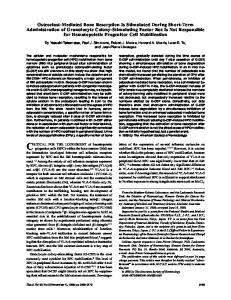
Figure 1: Reconstruction of a three-dimensional bone model from CT data by segmentation, surface conversion, meshing and HU value mapping according to [4].
is conceivable. Subsequently the model is covered with a grid, which is required to generate the NURBS surface. The model is transferred to the pre-processor via an IGES interface [4].
2.2 Preparation of the FE-model If the surface has no further gaps or holes, the surface model is converted into a solid model when the import in Abaqus/CAE is performed. Afterwards, the solid model is meshed automatically with tetrahedral finite elements. The mapping of the material data from the CT to the FE mesh is done node-wise. Employing the self-developed software Abactmat, each node gets an HU value from the CT data by using the corresponding node coordinates. The HU values are considered as temperatures, in order to simulate the inhomogeneous bone material properties in vivo by a linear-elastic temperature-dependent material model [5]. Correlations between HU and Young’s modulus or bone mineral density and Young’s modulus can be found in the literature [6]. The relationship between HU and bone mineral density can be determined through a bone mineral
density phantom, which should be CT-scanned together with the interesting bone structure [4]. In contrast, the application of the boundary conditions (forces, pressures, and displacements) in biomechanical FEA is mostly based on assumptions. Articular force measurements with specially instrumented implants such as OrthoLoad implants [7] or muscle force calculations based on inverse dynamics [8] cannot capture the entire spectrum of the constraints in vivo. Hence, the load, which is applied on the FE model, usually reposes on an available load from the literature like the maximum load during walking, sitting down or climbing stairs. The bearing of the bone model is performed in the articular centre points, while the articular forces and the muscle forces are applied on the model surface. All boundary conditions are implemented via reference points which are linked to the volume or surface through tie constraints. In order to avoid an excessive calculation time, the FEA can be performed with a static load and, if appropriate, carried out without nonlinearities. The interesting output parameters of the FEA have to be augmented by the node temperature and the output parameter, which should be acting as the basis of the mechanical stimulus. Through the output of the input file the FE model is made available for the bone remodelling simulation.
2.3 Bone remodelling The simulation of bone remodelling is implemented by the adaptation of the HU values to the FE-calculated mechanical stimulus. The aim is an optimally mineralized bone structure with high HU values in high stressed areas and low HU values in low stressed areas. In consequence, the stimulus in the whole bone structure gets more uniform. To adapt the HU values of the FE nodes, the local stimuli of the nodes are determined and compared with a reference stimulus, which represents the acceptable daily strain of the bone tissue. If the current stimulus is higher than the reference stimulus, the HU value of the node needs to be increased (bone formation). If the current stimulus is smaller, the HU value has to be reduced (bone resorption). Based on a mathematical function (Figure 2) the node-individual rate of bone turnover is calculated and a new HU value for the observed FE node is determined. Assuming that the current stimulus exceeds the maximum of bone formation, the overload leads to a necrotic bone resorption. If the current stimulus of the FE node is close to the reference stimulus, no adaptation of the HU value is required (equilibrium zone). To adapt the mathematical
Brought to you by | ReadCube/Labtiva Authenticated Download Date | 12/4/16 3:10 PM
J. Mauck et al.: Numerical simulation of mechanically stimulated bone remodelling | 645
Figure 2: Exemplary representation of the bone remodelling algorithm by Behrens [3], Field [2] (without necrosis) and Beaupre [1] (without maximum formation rate and necrosis).
function (Figure 2) to the desired bone model, the following parameters need to be defined: – Reference stimulus, – Magnitude of the equilibrium, – Zone of necrosis stimulus, – Rate of bone turnover and – Remodelling balance between formation and degradation. Moreover, the period of time represented by the FEA, and the weighting of different load cases (e.g. walking vs. climbing stairs) have to be clarified. By varying these input parameters, the bone remodelling rate can be changed and an increased bone formation or degradation is promoted. During the automatically proceeded optimization, FEA and HU-value adaptation are performed alternately, until a uniform strain or a previously defined termination criterion is reached. To start the process of bone remodelling simulation, the following steps are required: 1. The input parameters given above are entered in a pre-formatted text file (para.txt). 2. The temperature table, which contains the nodes and the current HU values to be remodelled, are exported from the input file (job.inp) into a new text file that is stored as HU file (job.huf). 3. Instead of the temperature table a cross-reference to the HU file is supplemented in the input file. 4. Python code (remodel.py), parameter text file (para.txt), input file of the FE model (job.inp), HU file (job.huf) and an environment file for Abaqus (abaqus.env) are placed in a separate file folder. Using a queue for the systematic processing of unsolved input files by the Abaqus solver, FEA and HU-value adaptation are performed automatically. After each FEA the
Figure 3: Interaction of the different file types during the bone remodelling: The process starts when the job.inp is detected by the FE queue. Regarding all input files the FE job is executed and the HU values are adapted. When the optimization process reaches the convergence or the termination criterion, the process is stopped [9].
HU-file is duplicated and edited to predetermine the new specific HU values for the following FEA. In which kind the files interact in detail is summarized in Figure 3 [9].
3 Results The result of the bone remodelling simulation is an output file (job.odb) for the Abaqus Viewer. This file contains the results of all FEA including the HU value distributions, which were used for the corresponding FEA cycles. In Figure 4 the results of a mechanically stimulated rat bone is shown exemplarily. The transcortical hole through the diaphysis of the femur is closed in vivo and in silico within a simulation time of 1 month postoperatively.
4 Discussion The relationship between morphology and mechanical stress in bones was already described in 1892 by Julius Wolff. Based on this theory, an organ-level strategy to simulate the load-driven remodelling in bones was developed.
Brought to you by | ReadCube/Labtiva Authenticated Download Date | 12/4/16 3:10 PM
646 | J. Mauck et al.: Numerical simulation of mechanically stimulated bone remodelling
Figure 4: Representation of the HU value distribution of the rat femur in the region of interest. Comparison of CT and FE images at different times: Using the bone remodelling algorithm by Beaupre [1] the results of the animal experiments could be simulated in a comparable time frame.
The aim was to predict the distribution of bone tissue and trabecular bone density with numerical bone models stimulated by stress or strain parameters [10]. Since these stimulation parameters have been questioned, new strategies driven by the removal of microdamages [11], regulated by biological parameters [12] and multiscale approaches were developed [10, 13]. Our presented bone remodelling algorithm is a loaddriven strategy, which is based on high-resolution CT data including the mineral density of bone. Thus, the patient-specific bone structure and the inhomogeneous material are considered. As the presented results show, the algorithm provides a realistically remodelled bone structure comparable to the result from the animal study. Nevertheless, an exact adjustment of the input parameters is necessary to obtain the correct reconstruction velocity and the desired degree of bone volume. For a reliable prediction of bone remodelling, the implementation of sensitivity analyses and experimental validations is essential. Summarized, our method represents a mechanically focused approach to analyse the macromorphology of bone under altered mechanical conditions or in combination with different implant designs and materials. Despite the fact that the proposed bone remodelling strategy provides a great opportunity to improve the choice of therapy in particular for complex bone defects, its use in clinical practice is not yet expedient. Besides the limitations of FE simulations related to bone structures like the complexity of the FE model creation, the lack of an assured bone material definition and the insufficient
knowledge concerning the load situation of different bone types, the question how to validate the method of bone remodelling simulation impairs the targeted application [11]. Today, validations using patient-specific data are not ethically acceptable because the patient would be exposed to an increased X-ray exposure due to frequent CT scans. Alternatively, a verification on an animal model can be performed, even if the healing process is affected through X-radiation and the transferability of the results to humans is difficult to prove because of restrictions due to different bone structures, surgical procedures and implant systems [11]. In the future a verification of the bone remodelling algorithm on human subjects might be realized if high resolution MRI scans can be used instead of CT scans. For this purpose, the development of a sufficiently hedged material definition of the bone tissue in vivo with respect to MRI specific metrics would be required in order to offer a method for bone remodelling simulation, which could meet the challenges of patient-specific modelling in later clinical use. Acknowledgment: We would like to thank Professor Annelie Weinberg and Ms. Elisabeth Martinelli, University Hospital Graz, for providing the animal CT scan.
Author’s Statement Research funding: The author state no funding involved. Conflict of interest: Authors state no conflict of interest. Material and Methods: Informed consent: Informed consent is not applicable. Ethical approval: The conducted research is not related to either human or animal use.
References [1] Beaupré GS, Orr TE, Carter DR. An approach for timedependent bone modeling and remodeling-application: a preliminary remodeling simulation. J Orthop Res. 1990;8:662–70. [2] Field C, Li Q, Li W, Thompson M, Swain M. Prediction of mandibular bone remodelling in-duced by fixed partial dentures. J Biomech. 2010;43:1771–9. [3] Behrens BA, Nolte I, Wefstaedt P, Stukenborg-Colsman C, Bouguecha A. Numerical investigations on the strain-adaptive bone remodelling in the periprosthetic femur: Influence of the boundary conditions. Biomed Eng Online. 2009;8:7. [4] Kluess D, Souffrant R, Mittelmeier W, Wree A, Schmitz KP, Bader R. A convenient approach for finite-element-analyses of orthopaedic implants in bone contact: Modeling and experimental validation. Comput Methods Programs Biomed. 2009;95:23–30.
Brought to you by | ReadCube/Labtiva Authenticated Download Date | 12/4/16 3:10 PM
J. Mauck et al.: Numerical simulation of mechanically stimulated bone remodelling | 647
[5] Zacharias T. Präoperative biomechanische Berechnung von Femur-Hüftendoprothese-Systemen zur Ermittlung der individuellen Primärstabilität nach Roboterimplantation. Aachen: Shaker Verlag; 2001. [6] Helgason B, Perilli E, Schileo E, Taddei F, Brynjólfsson S, Viceconti M. Mathematical relationship between bone density and mechanical properties: a literature review. Clin Biomech. 2008;23:135–46. [7] OrthoLoad [http://www.orthoload.com]. [8] Erdemir A, McLean S, Herzog W, van den Bogert AJ. Modelbased estimation of muscle forces exerted during movements. Clin Biomech. 2007;22:131–54. [9] Jonas R. Erarbeitung und Integration eines Algorithmus zum Bone-Remodeling für den Abaqus FE-Solver und Konstruktion einer Versuchsvorrichtung zur zellbiologischen Parameterbestimmung. University of Rostock: diploma thesis.
[10] Webster D, Müller R. In silico models of bone remodeling from macro to nano - from organ to cell. John Wiley & Sons. 2011;3:241–51. [11] Martínez-Reina J, Reina I, Domínguez J, García-Aznar JM. A bone remodelling model including the effect of damage on the steering of BMUs. J Mech Behav Biomed Mater. 2014;32:99–112. [12] Defranoux NA, Stokes CL, Young DL, Kahn AJ. In silico modeling and simulation of bone biology: a proposal. J Bone Miner Res. 2005;20:1079–84. [13] Hambli R. Connecting mechanics and bone cell activities in the bone remodeling process: an integrated finite element modeling. Front Bioeng Biotechnol. 2014;2:1–12. [14] Zadpoor AA, Weinans H. Patient-specific bone modeling and analysis: the role of integration and automation in clinical adoption. J Biomech. 2015;48:750–60.
Brought to you by | ReadCube/Labtiva Authenticated Download Date | 12/4/16 3:10 PM