Useful for object oriented design Java features are pack- ... of C or C++ [Nikishkov et al (2003)]. ..... making it comparable to performance of the analogous C.
c 2006 Tech Science Press Copyright �
CMES, vol.11, no.2, pp.81-90, 2006
Object Oriented Design of a Finite Element Code in Java G.P. Nikishkov 1
Abstract: This paper presents the object oriented approach to programming the finite element method using the Java language. The developed finite element code consists of ten Java packages. Three main methods are related to generation of finite element models, solution of elastic and elastic-plastic boundary value problems, and visualization of models and solution results. Objectoriented model of the code is described. It is demonstrated that Java 1.5 new features are useful in development of the finite element code. Java 3D is used for visualization of models and results.
gramming including creation of interactive codes with graphical user interface. Extensive bibliographical information on the object oriented approach in FEM and BEM is given by Mackerle (2004).
Mostly, object oriented finite element codes have been implemented in C++ programming language. It was shown that object oriented approach with C++ programming language could be used without sacrificing computational efficiency [Dubois-Pelerin and Zimmermann (1993)] in comparison to Fortran. A paper of Akin et al. (2002) advocates employing Fortran 90 for object oriented development of finite element codes since the keyword: Object oriented approach, Java, Java 3D, Fi- authors consider Fortran execution faster than C++. nite element method, Elastic, Elastic-plastic, VisualizaJava language introduced by Sun Microsystems postion. sesses features, which make it attractive for using in computational modeling. Java is a simple language (sim1 Introduction pler than C++). It has rich collection of libraries impleThe finite element method is used for computational menting various APIs (Application Programming Intermodeling in its original form [Bathe (1996)] for several faces). With Java it is easy to create Graphical User Indecades. Recently the method has been developed further terfaces and to communicate with other computers over in meshless form [Atluri and Shen (2002); Atluri(2004)]. a network. Java has built-in garbage collector preventing Finite element codes were traditionally developed in For- memory leaks. Another advantage of Java is its portatran and C languages, which support procedural pro- bility. Java Virtual Machines (JVM) are developed for gramming. During last fifteen years, finite element de- all major computer systems. JVM is embedded in most velopment is gradually shifting towards an object ori- popular Web browsers. Java applets can be downloaded ented approach. Forte et al (1990) in one of the first through the internet and executed within Web browser. publications on the object oriented approach to the fi- Useful for object oriented design Java features are packnite element development, presented essential finite el- ages for organizing classes and prohibition of class mulement classes such as elements, nodes, displacement and tiple inheritance. This allows cleaner object-oriented deforce boundary conditions, vectors and matrices. Sev- sign in comparison to C++. Despite its attractive feaeral authors described detailed finite element architec- tures, Java is rarely used in finite element analysis. Just ture using the object oriented approach. Zimmermann few publications can be found on object oriented Java fiet al. (1992) and Commend et al. (2001) proposed basics nite element codes [Eyheramendy and Guibert (2004)]. of object oriented class structures for elastic and elastic- Previously, Java had a reputation of relatively slow lanplastic structural problems. A flexible object oriented ap- guage because Java bytecode is interpreted by the JVM proach which isolates numerical modules from a struc- during execution. Modern just-in-time compilers used in tural model is presented by Archer et al. (1999). Macki the JVM make efficiency of Java code comparable to that devoted numerous papers and a book [Mackie (2001)] to of C or C++ [Nikishkov et al (2003)]. various aspects of the finite element object oriented pro- In this paper we present our variant of an object oriented design of the finite element code. The design is 1 University
of Aizu, Aizu-Wakamatsu 965-8580, Japan.
82
c 2006 Tech Science Press Copyright �
CMES, vol.11, no.2, pp.81-90, 2006
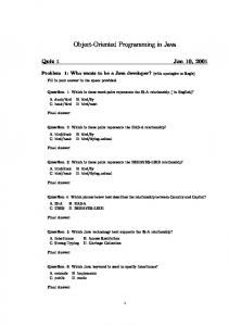
Our Jfea finite element system is organized into ten class packages as shown in Fig. 1:
fea model gener genutil
fea - main classes for mesh generation (Jmgen), problem solution (Jfem) and for visualization (Jvis);
util
elem
material
model - finite element model and loading; visual
util - utility classes; geom
elem - finite elements; gener - mesh generators;
Mesh generation
solver
Visualization
Problem solution Figure 1 : Packages of the finite element Java code.
genutil - utility classes for mesh generation; material - constitutive relations for materials; solver - assembly and solution of global finite element equation systems; visual - visualization of models and results;
fairly straightforward. We believe that the use of large amount of small objects can make the code too complicated for understanding and support. In addition it might lead to considerable time and space overhead. So, our approach is characterized by using larger objects and by using primitive types in computationally intensive parts of the code. The object oriented code consists of Java packages and implements three stages of the finite element analysis: mesh generation, problem solution and visualization of models and results. Next section presents general structure of the code. Then object models for finite element processor, mesh generator and visualizer are described in further sections. 2 General structure Finite element analysis is usually consists of three stages or three tasks: preprocessing (finite element model generation), processing (problem solution) and postprocessing (results visualization). In some programming languages like Fortran these three tasks are implemented in three separate computer codes. Since tasks have many common data and methods then three codes contain duplicated or similar code fragments. Code duplication makes more difficult code support and modification. In the Java language it is possible to have several main methods. The code (classes) can be organized into packages. A package is a named collection of classes providing package level of data protection. This eliminates necessity of code duplication and provides means for easy code reuse.
geom - geometry classes for visualization. Classes from four packages fea, model, util and elem are employed for all three tasks of finite element analysis - mesh generation, problem solution and visualization. Other packages contain specific classes for tasks. Packages gener and genutil are used for mesh generation. Packages material and solver are specific for problem solution. Packages visual and geom are designed for visualization stage of the finite element analysis. In the next sections we present the finite element processor, which obtains the solution of the boundary value problem. Later the object structure of the mesh generator and the visualizer are described. 3 Finite element processor 3.1 Class structure The finite element processor obtains the solution of the boundary value problem. It is the main part of the finite element analysis. The finite element processor uses classes form the following packages: fea, model, util, element, material and solver. Major classes of the finite element processor are shown in Fig. 2 Main class Jfem contains main method of the finite element processor. Typical finite element solution flow is composed of data input, assembly of the global equation system, solution of the equation system, computing stresses and results output. Constructor Jfem creates four objects responsible for performing computational procedure:
83
Finite Element Code in Java
Jfem (main) FeData
FeModel
Node
Solver
Element
Material
Element Quad2D
Element Quad3D
Elastic Material
Shape Quad2D
Shape Quad3D
Gauss Rule
Solver LDU
Solver PCG
ElasticPlastic Material
FeLoad
FeStress
ElemLoad
Elem FaceLoad
Figure 2 : Class diagram of the finite element processor. FeModel - finite element model, data input;
of the code. Object creation and destruction are expenSolver - assembly of the global stiffness matrix from el- sive operations. The use of large amount of small objects ement contributions, solution of the global equation can lead to considerable time and space overhead. Thus, we tried to find a compromise between using objects and system; providing computational efficiency. A possible way to FeLoad - load case, assembly of the global load vector; increase computing performance is using primitive types in place of objects. That is why information on the finite element model is mostly stored as scalar and arrays. FeStress - stress increment, results output. 3.2 Finite element model Main purposes of class FeModel are to read information on the finite element model, to store this information and to provide it to other classes. Class FeModel extends class FeData (Fig. 2). Class FeData contains scalars, arrays and objects used for description of the finite element model: Scalars: number of elements, number of nodes, number of degrees of freedom per node etc.; Arrays: node coordinates, displacement boundary conditions; Objects: elements, materials. Object-oriented approach allows to create reusable, extensible, and reliable code components. However, the extensive use of the object-oriented paradigm everywhere might not be always ideal for computational efficiency
New features of Java 1.5 include typesafe Enums and new class Scanner useful for data input. Enums is a flexible object-oriented enumerated type facility, which allows one to create enumerated types with arbitrary methods and fields. The java.util.Scanner class can be used to convert text into primitives or Strings. It also offers a way to conduct regular expression based searches on streams, file data and strings. A simple example below shows unformatted unordered input of two scalar variables nel and nnod using Java 1.5: enum vars { nel, nnod } int nel, nnod; Scanner sc = new Scanner(new File(s)); sc.useDelimiter("\\s*=\\s*|\\s+"); while (sc.hasNext()) { String name = vars.valueOf(sc.next); switch (name) { case nel: nel = sc.nextInt(); break; case nnod: nnod = sc.nextInt();
c 2006 Tech Science Press Copyright �
84
Table 1 : Description of class Element.
} }
Input file may contain expressions of the type nnod = 200
CMES, vol.11, no.2, pp.81-90, 2006
nel = 100
in free format and in any order. Names and values of the variables are separated by equal sign and any number of blanks. In the above code fragment, names of the variables are declared in enum vars. Scanner object sc is created for the file with the name String s. Method sc.useDelimiter sets equal sign and blank as delimiters for the input text. Method sc.hasNext allows to check if this scanner has another token in its input. Methods sc.next and sc.nextInt read string and integer from the input. 3.3 Element Class Element represents a base abstract class for all finite element types. Description of Element is given in Table 1. Each element object contains element name, material number, array of nodal connectivities and arrays of accumulated stresses and stress increment. Constructor Element creates element object using its name, number of nodes and number of integration points where stresses are stored. In the code, element objects are created using constructor NewElement with element name. NewElement class contains all element types in enum structure. The Java 1.5 enum declaration defines a full-fledged class (dubbed an enum type). It allows one to add arbitrary methods and fields to an enum type and to implement arbitrary interfaces. Constructor NewElement creates element objects of different types employing just element names. Classes ElementQuad2D and ElementQuad3D inherit some methods from class Element and implement actual methods for the two-dimensional quadrilateral element with 8 nodes and for the three-dimensional hexahedral element with 20 nodes. Both elements have quadratic interpolation of geometry and field variables. Classes ShapeQuad2D and ShapeQuad3D contain methods for quadratic shape functions. Methods of a particular element class compute stiffness matrix, thermal vector, equivalent nodal load, strains at integration point and perform other necessary element operations (see Table 1).
Element + name: String + matNo: int - connectivities: int[] - sStress: double[][] - dStress: double[][] - stiffMat: static double[][] - elemVec: static double[] - elemCoords: static double[][] - elemTemps: static double[] + Element(String name, int nCon, int nGauss) + stiffnessMatrix(): double[][] + thermalVector(): double[] + equivFaceLoad(ElemFaceLoad surLd): int + getElemFaces(): int[][] + getStrainsAtIntPoint(int intPoint): double[] + getTemperatureAtIntPoint(int intPoint): double + extrapolateToNodes(double[] vAtIntPoints): double[] + setElemConnectivities(int[] indel) + setElemMaterial(int mat) + setElemXy() + setElemXyT() + getElemMaterial(): int + getElemXy(): double[][] + setElemT(): double[] + assembleElemVector(double[] glVector) + disAssembleElemVector(double[] glVector) + getElemConnectivities(): int[]
3.4 Material Class Material is a base abstract class for material constitutive equations. Table 2 provides methods of Material class.
Table 2 : Description of class Material. Material + stressState: String - elastModulus: double - poissonRatio: double - thermExpansion: double - properties: double[] + Material(String stressState) + getConstitutiveMatrix(): double[][] + strainToStress(double[] ep, double t, double[] sig) + setElastModulus(double e) + setPoissonRatio(double nu) + setThermExpansion(double alpha) + setProperties(double[]p) + getElastModulus(): double + getPoissonRatio(): double + getThermExpansion(): double + getProperties(): double[]
85
Finite Element Code in Java
Classes ElasticMaterial and ElasticPlasticMaterial extend class Material. Method getConstitutiveMatrix provides elasticity matrix or elastic-plastic constitutive matrix. Method strainToStress computes stress increment using given strain increment. 3.5 Equation solver Base abstract class Solver includes methods for assembly and solution of the global equation system. Its major methods are:
Jmgen (main) Hashtable FeData 2D mesh generators 3D mesh generators
FeModel Node
Element
Paste Mesh transform
Figure 3 : Class diagram of the finite element preprocesassembleGlobStifMat() - assembly of the global stiffsor. ness matrix; assembleElemStifMat() - assembly of element contribution to the global stiffness matrix; 4 Mesh generation solve(double x[ ]) - solution of the global equation sys4.1 Block-decomposition method and code structure tem with the right-hand side x. Mesh generation in the Jfea code is based on the blockdecomposition method [Schneiders (2000)]. In the block-decomposition method, the user divides a solution domain into multiple blocks in such a way that each block is suitable for the local meshing process. Mesh generation within blocks is performed by various mesh generators. Some blocks can be meshed using both twodimensional and three-dimensional approaches. First, two-dimensional mesh is created. Then this mesh is swept in space to produce three-dimensional mesh block. A pair of generated mesh blocks can be pasted together Currently the Java compiler does not have enough means in order to create new mesh block. for powerful code optimization. Because of this an at- Class diagram of the finite element preprocessor is shown tention should be devoted to a code tuning. It is nec- in Fig. 3. Class Jmgen contains main method and actiessary to identify code segments, which consume ma- vates all other classes necessary for mesh creation. Each jor computing time and to tune them manually. Tuning class performs some action on one or more finite element of the equation systems solution procedure is discussed models. FeModel objects are stored in a hashtable blocks. by Nikishkov et al (2003). During LDU decomposition For example, any mesh generator can create a mesh block of the global stiffness matrix, triple loop in which one as FeModel and can put it in blocks hashtable under the matrix column is used to modify another column, takes name specified by the user. most computing time. Tuning can be done by unrolling Since all modules are independent then main class calls two outer loops. In the tuned LDU decomposition a them by name of its class as shown in the following code block of matrix columns modifies another block of mafragment. trix columns thus economizing data loads from memory. Tuning of the PCG solution is performed by unrolling Scanner sc = new Scanner(new File(s)); one inner loop in sparse matrix-vector product. while (sc.hasNext()) {
Class Solver does not contain any information about storage schemes for the global stiffness matrix and about solution methods. Particular storage and solution methods are implemented in subclasses, which extend Solver. Subclass SolverLDU implements LDU decomposition method for the solution of the global equation system stored in the symmetric profile format. Subclass SolverPCG uses preconditioned conjugate gradient (PCG) method for the solution of equation system with a storage in sparse row format.
While tuning requires some additional efforts, its use may considerably enhance performance of the Java code making it comparable to performance of the analogous C code.
String c = sc.next().toLowerCase(); if(name.equals("#")) { sc.nextLine(); continue; }
86
}
c 2006 Tech Science Press Copyright �
CMES, vol.11, no.2, pp.81-90, 2006
Class w = Class.forName("gener."+c); w.newInstance();
than a specified tolerance then two nodes are merged. This means the node is deleted from the second mesh and its number is registered in a list for subsequent modification of the connectivity information.
Here the scanner sc reads data from an input file. If a Other operations on mesh blocks include: read token appears to be ”#” then this line is considered a comment and the scanner reads token from the next line. transform - translate, scale and rotate node locations of a mesh block; If string c is not a comment character it is supposed to be a class name. New object c from package gener is copy - create a copy of a mesh block under new name; created using methods forName and newInstance. delete - remove a mesh block from the hashtable; readmesh - read a mesh block from a file; 4.2 Mesh generators writemesh- write a mesh block to a file. Various mesh generators can be included in the code without any difficulty. A mesh generator creates 5 Visualization FeModel object. Generated nodes and elements are 5.1 Using Java 3D API placed in the FeModel object using its appropriate methods. Then the model object is stored in hashtable blocks. In general, the development of visualization software is a Usually one mesh block has simple shape and topology. complicated task. One possibility to make this task simBecause of this relatively simple mesh generators based pler is to employ well-established visualization tools like on mapping from local to global coordinates can be used. the Visualization Toolkit VTK [Schroeder et al (1998)]. Two such mesh generators are implemented in the post- Such tools have a lot of opportunities for visualization. processor code. Class genquad2d contains a mesh gen- Nevertheless, particular features necessary for finite eleerator for a two-dimensional quadratic quadrilateral area. ment visualization, especially in the case of higher-order The area is specified by eight nodal points. Regular mesh elements, may be missing. is generated in local coordinates. Then nodal coordi- Fortunately, Java provides an object-oriented graphics linates are transformed into the global cartesian system us- brary for three-dimensional visualization, which is called ing quadratic shape functions. Similar three-dimensional the Java 3D [Sowizral et al (2000)]. The developer specclass genquad3d generates a mesh inside a curves hex- ifies geometry of visual objects, their appearance and beahedral area, which in general is determined by twenty havior and light sources as Java 3D objects. Java 3D obnodal points. jects are placed into a scene graph data structure. The Another useful method for three-dimensional mesh gen- scene graph is a tree structure that specifies the content eration is sweeping a two-dimensional mesh in space. of a virtual universe, and how it is to be rendered. AfMesh generator sweep extracts a two-dimensional mesh ter compiling, the scene is rendered automatically with with a given name from hashtable and moves it ”quasi”-photographic quality. The latter means that the along specified three-dimensional trajectory. The two- effects of light source shading are shown, however, obdimensional mesh is copied at predetermined positions. ject shades and reflections are ignored. These two-dimensional sections serve as a skeleton for The Java 3D employs linear triangular and quadrilateral creation of a three-dimensional mesh. Application of filled polygons for surface representation. Visualization transformations to two-dimensional sections allows to of finite element models consisting of simplest elements produce complicated three-dimensional meshes. is almost straightforward. However, for higher order elements the transformation of element surfaces into trian4.3 Connecting blocks and other operations gular polygons should be done carefully taking into acMesh blocks are connected together by pasting surfaces count both geometry features and result field gradients. with coincident nodes. Class paste provides a method 5.2 Visualization algorithm for producing new mesh from given two mesh fragments. Surface nodes of two mesh fragments are compared to The input data for the visualization is a finite element each other. If a distance between a pair of nodes is less model produced by the preprocessor Jmgen (no results)
87
Finite Element Code in Java
or by the processor Jfem (contains solution results). Primary results (displacements) are obtained at nodes of the finite element model. Secondary finite element results (like stresses), which are expressed through derivatives of the primary results, usually have the best precision at some points inside elements. For models composed of 20-node finite elements stresses have the most precise values at 2 × 2 × 2 reduced Gaussian integration points. If two-dimensional 8-node elements are used, the best values of stresses are at 2 × 2 Gauss integration points.
Jvis (main) Mouse FeData
VisModelShape
Light
FeModel
VisModel Geometry
Contour Texture
Node
Element
ElementFace
Delaunay Triang
The visualization algorithm consists of the following Figure 4 : Class diagram of the finite element postpromain steps [Nikishkov (2003)]. cessor. Obtain continuous field of finite element results by extrapolation from reduced integration points inside elements to element nodes with subsequent averaging. Create the surface of the finite element model or create model section where results will be displayed. Subdivide curved element faces into flat triangles on the basis of surface curvature and gradient of results. Create contour pictures by specifying coordinates of one-dimensional color pattern at triangle vertices.
curved element surfaces. A one-dimensional texture containing desired number of color bands is generated. Values of functions at triangular vertices are transformed to texture coordinates using specified scale.These texture coordinates are supplied to the Java 3D rendering engine, which generates a three-dimensional image. 5.3 Visualization code structure
Class structure of the visualization code is shown in Fig. 4. The code serves as a model visualizer and as a In order to obtain continuous stress fields, stresses at re- postprocessor of the finite element results. duced integration points are extrapolated to finite element nodes and are averaged with the use of contributions Main class Jvis creates object VisModelShape. This obfrom adjacent finite elements. After this, nodal stresses ject contains all necessary information for Java 3D scene can be interpolated inside elements using element shape graph including visual model shape, mouse behavior (class Mouse) and lights (class Light). Class VisModelfunctions. Geometry creates geometric arrays for the visual model Creation of the model surface is based on the fact that using data of the finite element model FeModel. Class outer element faces are present in the model only once DelaunayTriang helps to triangulate element faces Emewhile inner faces belong to two finite elements. The sur- nentFace using Delaunay triangulation algorithm. Class face of the finite element model is created from element ContourTexture creates textures necessary for visualizafaces, which are mentioned in element connectivities one tion of finite element results as color contours. time. Subdivision of quadratic element faces depends on two factors: curvature of the surface and range of result function over the surface. The subdivision into triangular elements is performed using the Delaunay triangulation procedure. Numbers of subdivisions on face edges are determined by its curvature and by results ranges between nodes.
6 Example
Java 3D provides three-dimensional rendering of polygons with a possibility of texture interpolation. Texture interpolation technique is employed to create color contours inside triangles produced after subdivision of
Mesh is generated for one eights of the specimen (see Fig. 5.a). A schematic of mesh generation is depicted in Fig. 5.b. A two-dimensional area is decomposed into blocks b1, b2 and b3 of simple shapes. Two-dimensional
Let us demonstrate the use of the finite element Java system Jfea on a simple example shown in Fig. 5.a: tension of a thick rectangular plate with a central hole. 6.1 Mesh generation
88
c 2006 Tech Science Press Copyright �
P=1
CMES, vol.11, no.2, pp.81-90, 2006
Table 3 : Data file for mesh generation.
sweep
b3 8 R=1
b2
2
4
b1
y z a
x b
Figure 5 : Example problem: a) tensile plate with a hole; b) mesh generation using block decomposition and sweeping.
meshes inside blocks are created by local mesh generators. Block are pasted together in one mesh. Subsequent sweeping produces a three-dimensional mesh. Twodimensional meshes are composed of 8-node quadrilateral elements. The 20-node hexahedral element is used in the three-dimensional mesh. Input data for preprocessor Jmgen is given in Table 3. The first line in the Table is a comment. A rule for comments is as follows: after token #, the rest of the line is ignored. Uppercase and lowercase characters can be mixed freely since all characters are transformed to lowercase during data interpretation. Mesh blocks b1 and b2 are produced by GenQuad8 generator. Key points shown in Fig. 5.b by dark circles are specified in array xyp to define curved quadrilaterals. Relative sizes of smallest elements on edges are determined by values in array res. Free format data input provides a possibility to use default values of parameters. For example, it is not necessary to specify array res if all elements should have equal size along edges of a quadrilateral block. In the absence of array res default zero values are adopted that means equal element size along edges. Mesh blocks b1 and b2 are connected together by Paste module. The resulting mesh is stored under the name b12. Parameter eps determines coordinate tolerance for joining nodes from two mesh blocks.
# Data file for Jmgen Genquad8 b1 nh = 4 nv = 4 xyp = 1 0 0 0 2 0 0 0 2 2 0 0 .7071 .7071 .9239 .3827 res = .15 .15 0.85 0 end GenQuad8 b2 nh = 4 nv = 3 xyp = .7071 .7071 0 0 2 2 0 0 0 2 0 0 0 1 .3827 .9239 res = .15 0 0.85 0 end Paste b1 b2 b12 eps = 0.01 end Rectangle b3 nx = 3 ny = 3 xs = 0 0.6667 1.3333 2 ys = 2 2.6667 3.3333 4 end Paste b12 b3 b123 eps = 0.1 end Sweep b123 m3d nlayers = 4 zlay = 0 .25 .5 .75 1 end WriteMesh m3d example.mesh
Upper block b3 is meshed by module Rectangle, which creates a mesh inside a rectangular block using specified locations of corner nodes at block edges. Another pasting of mesh blocks b12 and b3 produces a final twodimensional mesh b123. A three-dimensional mesh m3d is created by sweeping the two-dimensional mesh b123 along the negative direction of z axis. Resulting three-dimensional mesh is written to file example.mesh using module WriteMesh. The mesh is used by the processor code Jfem during problem solution. The mesh can be visualized by the visualization code Jvis. 6.2 Problem solution Input data for the finite element processor is presented in Table 4. Small amount of data is necessary since the mesh prepared by the preprocessor is included using instruction includeFile. A principle of adopting default values of many parameters is also contribute to the re-
89
Finite Element Code in Java
Table 4 : Data file for finite element solution. # Data file for Jfem stressState = threeD includeFile example.mesh solver = LDU # Material properties materNo = 1 elastModulus = 1000 poissonRatio = 0.3 # Displacement boundary conditions boxConstrDispl = x 0.0 -0.01 0.99 -1.01 0.01 4.01 0.01 boxConstrDispl = y 0.0 0.99 -0.01 -1.01 2.01 0.01 0.01 boxConstrDispl = z 0.0 -0.01 -0.01 -1.01 2.01 4.01 -0.99 # Load loadStep = 1 boxSurForce = n 1.0 -0.01 3.99 -1.01 2.01 4.01 0.01
sionally created simple. Parameters related to what and how to be visualized are given on the command line or in data file. Possible ways of visualization include: model, deformed model, contour plots of various quantities for deformed and undeformed models. 7 Conclusion In this paper, the architecture of a finite element system written in Java has been presented. The system is designed according to object oriented principles. Is is organized into ten Java packages. Four packages are shared between all three codes, other six packages are specific for applications. The system has three main methods corresponding to three applications: preprocessor for mesh generation, processor for stress analysis and postprocessor for visualization.
We find that new features of Java 1.5 like data scanner and enumerated type are very helpful in development of finite element applications. Java 3D API provides means duction of input data. For example, the instruction for easy visualization of finite element models and resolver = LDU sults. Acceptable computational efficiency of the Java specifies that LDU method is employed for the solution code can be achieved with solver code tuning. of the finite element equation system. This instruction The general conclusion is that object oriented approach can be omitted since LDU solver is the default one. with programming in Java allows to develop wellNext, material properties are specified. For material organized finite element applications with acceptable number materNo we determine just mechanical con- computational efficiency. While here the object oriented stants that are necessary for the selected type of analysis. design has been applied to the traditional finite element Different options exist for the specification of boundary algorithm, it can be also used for codes based on meshconditions. In the example, both displacement bound- less methods. ary conditions and force boundary conditions are generated on surfaces, which are identified by a bounding box References with given diagonal ends. Instruction boxConstrDispl implies that the following data is given: constraint direc- Akin, J.E.; Singh, M. (2002): Object-oriented Fortran tion, constraint value, three coordinates of the first diago- 90 P-adaptive finite element method. Advances in Enginal end and three coordinates of the second diagonal end. neering Software, 33, 461-468. Specification of a normal distributed force on a surface is Archer, G.C.; Fenves, G.; Thewalt, C. (1999): A new performed in an analogous way. object-oriented finite element analysis program architecComputing time for the example problem (148 20-node ture. Computers and Structures, 70, 63-75. elements and 907 nodes) is 1 s on a PC computer with Atluri, S.N.; Shen, S. (2002): The Meshless Local Intel Pentium 4 2.8MHz processor. Petrov-Galerkin (MLPG) Method: A Simple and lesscostly alternative to the finite element and boundary ele6.3 Visualization of results ment methods. CMES, 3, 11-52. The created finite element model and results of problem solution are visualized using postprocessor Jvis as shown in Fig. 6. Using mouse the user can rotate, zoom and pan the finite element model. The user interface is inten-
Atluri, S.N. (2004): The Meshless Method (MLPG) for Domain and Bie Discretizations. Tech Science Press, Los Angeles. Bathe, K.-J. (1996):
Finite Element Procedures.
90
c 2006 Tech Science Press Copyright �
CMES, vol.11, no.2, pp.81-90, 2006
Figure 6 : Visualization of the generated finite element mesh and graphical presentation of results (equivalent stress) as contours. Prentice-Hall, Englewood Cliffs, NJ.
3D Graphics. Prentice-Hall, Englewood Cliffs, NJ, Commend, S.; Zimmermann, T. (2001): Object- USA. oriented nonlinear finite element programming: a primer. Sowizral, H.; Rushforth, K.; Deering, M. (2000): The Java 3D API Specification. Addison-Wesley, Reading, Advances in Engineering Software, 32, 611-628. Dubois-Pelerin, Y.; Zimmermann, T. (1993): Object- MA. oriented finite element programming. III. An efficient Zimmermann, T.; Dubois-Pelerin, Y.; Bomme, P. implementation in C++. Computer Meth. Appl. Mech. (1992): Object-oriented finite element programming. I. Governing principles. Computer Meth. Appl. Mech. Eng. 108, 165-183. Eyheramendy, D.; Guibert D. (2004): A Java approach Eng. 98, 291303. for F.E. computational mechanics. (P.Neittaanmaki et al eds.), 13 p.
ECCOMAS 2004
Forde, B.W.R.; Foschi, R.O.; Steimer, S.F. (1990): Object-oriented finite element analysis. Computers and Structures, 34, 355-374. Mackie, R.I. (2001): Object oriented methods and finite element analysis. Saxe-Coburg Publications, Stirling, Scotland. Mackerle, J. (2004): Object-oriented programming in FEM and BEM: a bibliography (1990-2003). Advances in Engineering Software, 35, 325336. Nikishkov, G.P. (2003): Generating contours on FEM/BEM higher-order surfaces using Java 3D textures. Advances in Engineering Software, 34, 469-476. Nikishkov, G.P.; Nikishkov, Yu.G.; Savchenko, V.V. (2003): Comparison of C and Java performance in finite element computations. Computers and Structures, 81, 2401-2408. Schneiders, R. (2000): Quadrilateral and hexahedral element meshes. In: Handbook of Grid Generations (J.F.Thompson et al Eds, CRC Press, 21.1-26. Schroeder, W.; Martin, K.; Lorensen, B. (1998): The Visualization Toolkit: An Object-Oriented Approach to