JOURNAL OF APPLIED PHYSICS
VOLUME 88, NUMBER 11
1 DECEMBER 2000
On contrast parameters and topographic artifacts in near-field infrared microscopy D. V. Palanker,a) D. M. Simanovskii, P. Huie, and T. I. Smith Picosecond Free Electron Laser Center, W. W. Hansen Experimental Physics Laboratory, Stanford University, Stanford, California 94305
共Received 27 October 1999; accepted for publication 7 September 2000兲 Near-field microscopy overcomes the diffraction limit through the partial conversion of the evanescent fields, formed around the subwavelength sources of light, into propagating waves by interactions between the probe and the sample. Contrast parameters in this imaging technique are quite different from those in conventional 共far-field兲 optics. We study the mechanisms of image formation in the transmission mode of a near-field microscope in the mid-infrared part of the spectrum 共6–10 m兲. The amount of light propagating from a subwavelength aperture through a flat substrate 共‘‘allowed’’ light兲 is found to strongly increase as the tip approaches the sample, generating topographic artifacts in near-field images. Such artifacts can be eliminated by flat sample preparation techniques. The transmitted power is strongly influenced by the refraction index of the sample resulting in a substantial difference of the near-field spectrum from the far-field one. A model describing tunneling of light through a subwavelength aperture into the substrate has been developed and is in very good agreement with the experimental data. The model predicts that spectral sensitivity is enhanced with smaller tip diameters. © 2000 American Institute of Physics. 关S0021-8979共00兲09023-X兴
I. INTRODUCTION
Strong attenuation of light in the subwavelength part of the tapered fiber 共10⫺6 – 10⫺4 typically10兲 together with heating of the fiber coating by light11 limit the output signal and, consequently, the size of the aperture. To overcome these limitations, apertureless schemes have been developed which are based on detection of light scattered from oscillating tapered metal tips.12,13 Features smaller than 100 nm have been imaged at 10.6 m wavelength 共CO2 laser兲.14,15 This approach, based on a lock-in detection of the signal, requires continuous 共or at least ms-long pulsed兲 lasers. Due to the lack of convenient continuous sources of tunable mid-IR radiation, suitable for purposes of spectroscopy, we explore a fiber-based approach to near-field imaging and spectroscopy utilizing pulsed IR lasers. Contrast parameters in various modes of the near-field microscopy 共transmission, reflection and scattering兲 may be very different from those of conventional 共far-field兲 microscopy. Although this issue has attracted growing attention in recent years,16–18 the mechanisms of image formation are not yet well understood, and different contrast parameters have been claimed by various researchers using similar techniques.13,15 In the present work we study the contrast parameters in transmission mode 共fiber-based兲 near-field microscopy, including the influence of the sample and substrate refraction indices, as well as the role of sample topography in near-field image formation.
Infrared 共IR: 5–12 m兲 spectroscopy is a widely used sensitive technique for detection and characterization of molecules. Current biomedical applications of Fourier transform infrared 共FTIR兲 microspectroscopy include identification of tumor cells1 and bacteria,2 mapping of calcified atherosclerotic plaques3 and brain tissue,4 finding foreign material in tissue,5 etc. In these applications spatial resolution is typically limited to about 25–50 m due to either imperfection of the imaging optics or the beam quality of the IR source. Highly collimated beams from synchrotron radiation allow for achieving a diffraction limited resolution,6 namely one wavelength with the objective of 0.6 NA. This resolution was already sufficient to attempt imaging of protein and lipid distribution in large 共20 m兲 cells.6 For further improvement of the spatial resolution a scanning near-field optical microscopy has been developed that provides subdiffraction-limited resolution using a subwavelength size source 共or collector兲 of radiation which is raster scanned over the sample surface at small 共several nanometers兲 distance.7 As a light source 共or collector兲, very fine tapered fiber tips are generally used, coated with a thin layer of metal to prevent light leakage except at the very end of the tip where there is a small aperture. In the mid-IR part of the spectrum resolution of /4 共namely 1 m at ⫽4 m8 and 2 m at ⫽8 m9兲 has been demonstrated. In addition to the subwavelength resolution, this approach allows for underwater imaging of thin samples 共living cells, for example, Ref. 9兲 which is problematic with conventional FTIR microscopes due to strong water absorption of the IR radiation.
II. EXPERIMENTAL SETUP A. Near-field probe
Our experiments have been performed in two spectral regions: 6–7 m, and 9.2–10.7 m using the Stanford Picosecond Free Electron Laser 共FEL兲 and a pulsed grating-
a兲
Electronic mail:
[email protected]
0021-8979/2000/88(11)/6808/7/$17.00
6808
© 2000 American Institute of Physics
Downloaded 22 Feb 2001 to 171.64.108.234. Redistribution subject to AIP copyright, see http://ojps.aip.org/japo/japcpyrts.html
Palanker et al.
J. Appl. Phys., Vol. 88, No. 11, 1 December 2000
stabilized CO2 laser 共J48G-1W-36, Synrad Inc. Mukilteo, WA兲, respectively. Chalcogenide glass fibers 共Amorphos Materials Inc., Garland, TX兲 with a 100 m core were used to deliver the infrared radiation to a metal-coated tapered tip with a subwavelength opening at the apex, which served as a near-field probe. Sharp tips 共radii of curvature at the apex were less than 1 m兲 were produced by chemical etching in Piranha solution 共7:3 mixture of concentrated sulfuric acid and 30% hydrogen peroxide兲.19 These tips were completely coated with gold 共150 nm thickness兲 by vacuum evaporation, and the level of residual leakage of light from the tip was measured using a liquid nitrogen-cooled mercury cadmium telluride 共MCT兲 detector 共KMPV50-.5-J2, Kolmar Technologies Inc., Phoenixville, PA兲. Only tips with a leakage level bellow the detectable threshold 共2 nW兲 were selected. They were mounted on a piezo scanning stage 共NSOM 100, Nanonics Inc., Jerusalem, Israel兲, positioned on an inverted microscope 共Axiovert 35, Zeiss Inc.兲, and scanned across fine polishing paper 共0.05 m grain size兲 until a detectable IR signal appeared. Measurements performed with a scanning electron microscope have shown that a typical aperture size was about 1 m. This method enabled us to create high quality optical probes with a light source well localized at the apex of the tip.
6809
FIG. 1. Schematic representation of the illumination-mode near-field microscope built on a conventional inverted microscope with a sheer force-based feedback system.
B. Positioning of the probe
Sheer force feedback was employed for control of the distance between the tip and the sample. The optical probe was mounted on one arm of a standard 32 768 Hz tuning fork. With the probe attached the resonance frequency was shifted typically to 32 kHz and the quality factor was about 300. The tuning fork was driven by a 10 mV sinusoidal signal at the resonance frequency. Current in the circuit was detected by a lock-in amplifier 共EG&G, model 5210兲 and used to control the feedback system 共SPM100, RHK Technologies, Rochester Hills, MI兲. This technique allowed us to maintain the distance between the tip and the sample with a precision of a few nanometers. To ensure that optical detection conditions would be constant during scanning, the probe was fixed at the focus of the IR objective and the sample was moved 共see Fig. 1兲. The vertical axis of the three-dimensional piezo scanning stage was used to maintain contact with the probe, while the X and Y axes were used for lateral scanning. The scanning rate was determined mainly by the feedback response time, and it took typically 10 s per line of 128 pixels. C. Optical setup
The near-field microscope used in our experiments was mounted on an inverted optical microscope, so that the sample could be observed using transmitted as well as reflected light, allowing for precise positioning of objects with respect to the near-field probe. Radiation transmitted through the sample and the substrate was collected with a reflective objective 共50⫻, NA 0.45, Ealing Inc.兲 and registered by a MCT detector positioned in the focal plane of the objective. In this configuration only the small part of the optical probe close to the apex was imaged on the detector’s sensitive area
(0.3⫻0.3 mm) providing a strong suppression of any background radiation which might originate from imperfections in the gold coating of the optical probe. D. Sample preparation
To investigate contrast parameters and mechanisms of near-field image formation, objects with well-known optical properties and simple geometrical shapes were chosen. Most of the measurements were performed with polystyrene droplets deposited onto a calcium fluoride substrate. Standard polystyrene beads with 1 and 3 m diameters were deposited onto the substrates from a water suspension. The balls were fixed on the substrate by heating it to a temperature slightly in excess of the softening temperature of polystyrene 共⬃100 °C兲. The resulting structure appeared to be a set of single polystyrene droplets with a diameter slightly exceeding the initial diameter of the beads 共due to flattening兲. In addition to the calcium fluoride 共refraction index n⫽1.3), gallium phosphate (n⫽3.0) and germanium (n⫽4.0) substrates were tested as well. III. EXPERIMENTAL RESULTS AND PHENOMENOLOGICAL MODEL A. Approach curves
Subdiffraction limited resolution in near-field microscopy results from the interaction of the nonpropagating electromagnetic field generated around the probe with the sample.20 Since the evanescent fields decrease rapidly with distance 共on the order of a tip diameter兲, this interaction depends strongly on the separation between the near-field probe and the sample. Thus the sample topography is heavily involved in the near-field image formation.
Downloaded 22 Feb 2001 to 171.64.108.234. Redistribution subject to AIP copyright, see http://ojps.aip.org/japo/japcpyrts.html
6810
Palanker et al.
J. Appl. Phys., Vol. 88, No. 11, 1 December 2000
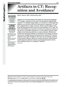
FIG. 2. Approach curve measured on a hemispherical silicon substrate at 9.3 m wavelength with tip diameter of 0.8 m. The dashed line represents model calculations.
The most direct way to characterize the influence of topography on the near-field signal is to measure approach curves, i.e., transmitted IR signal versus the distance between the probe and the substrate. In order to distinguish between the ‘‘allowed’’ and ‘‘forbidden’’ light 共i.e., light propagating inside the substrate at the angles below and above, respectively, of the total internal reflection angle on the substrate/air interface兲 we performed measurements on two types of substrates. The first was a flat silicon wafer with parallel surfaces which transmits only the allowed component, while the second had a flat upper surface and a hemispherical bottom which allowed for detection of both the allowed and the forbidden components of the total signal. Approach curves measured on these substrates (n⫽3.4) with a tip diameter of 0.8 m at a wavelength of 9.3 m and normalized to the far-field signal 共large separation between the tip and the substrate兲 are shown in Figs. 2 and 3. The signals rapidly increase as the separation between the tip and the substrate becomes smaller than ⬃0.5 m and reach the levels of 100⫾5 for the total signal 共hemispherical substrate兲 and 4⫾0.2 for its allowed component 共flat substrate兲. B. Theoretical model
In an attempt to characterize quantitatively the near-field signal as a function of the tip diameter, tip-sample separation, and the sample index of refraction, we have developed
FIG. 4. Schematic representation of the potential barrier for photons in the subcutoff part of the taper, and its penetration into air and the substrate to the depth of the ‘‘formation length’’ of the propagating wave. Z is the width of the air gap between the probe and the substrate.
a phenomenological model which describes the experimental situation as one-dimensional photon tunneling from the fiber through the ‘‘forbidden zone’’ of the subwavelength taper into the substrate. It is not unusual to consider photon propagation through subwavelength structures as quantum tunneling,21,22 but since there is no unambiguous potential which can be assigned to the photon, any particular case requires certain assumptions and has its own limitations. The diagram of the potentials used in our model is shown in Fig. 4. The potential barrier related to the penetration of light through the subwavelength tapered fiber tip can be considered as being formed of two components: barrier in the subcutoff region of the taper, and a barrier corresponding to emission from the subwavelength aperture. The tunneling probability can be written in the form
冉
T⬀exp ⫺
冕 冑 Z max
U共 z 兲2⫺
z min
冉冊 冊 B
2
dz ,
共1兲
where U(z) is a potential, B/ represents the photon energy, Z min ,Zmax are the ends of the barrier, where U(z min) ⫽U(zmax)⫽B/. Attenuation of the field inside the taper is determined by the imaginary part of the wave vector in axial direction23 k z ⫽ 冑k 20 ⫺k T2 ,
冉 冉冕 冑 z2
T⬀ exp iC
z1
k 20 ⫺k T2 dz
冊冊
共2兲 ,
where k 0 is the photon wave number, and k T is the transverse component. The imaginary part of k z is nonzero in the area where k T ⬎k 0 . Inside the taper k T is reciprocal to the diameter of the waveguide,23 thus transmission through the subcutoff taper can be expressed as the following:
冉 冕冑 冉
T⬀ exp iC
z2
z1
FIG. 3. Approach curve measured on a flat silicon substrate at 9.3 m wavelength using tip of 0.8 m diameter.
k 20 ⫺
A n 1 •d 共 z 兲
冊 冊 2
dz .
共3兲
This allows one to assign each point of the tapering zone a certain potential, which is a function of the taper diameter d(z) and n 1 , the index of refraction of the fiber
Downloaded 22 Feb 2001 to 171.64.108.234. Redistribution subject to AIP copyright, see http://ojps.aip.org/japo/japcpyrts.html
Palanker et al.
J. Appl. Phys., Vol. 88, No. 11, 1 December 2000
U共 z 兲⫽
冉
冊
A , for z⬍0. n 1 •d 共 z 兲
The second part of the photon path—the subwavelength zone to the right of the aperture—represents another obstacle. Since a propagating wave cannot exist in a subdiffraction limited volume, we assume that the photon will experience the potential barrier not only within the plane of the aperture, but also behind it, until the wave extends in space to dimensions above the diffraction limit. Since the width of the spherical wavefront extends linearly with its radius, the height of the potential barrier will scale reciprocally with the distance from the aperture. Thus for the area to the right of the aperture (z⬎0) we can describe the potential in the following way: U共 z 兲⫽
冉
冊
A , n• 共 z⫹d 兲
where n(z) is the refraction index of the media outside the fiber and A is a constant, which will be determined below. Since in all our experiments only the conditions outside the fiber have been varied, and all measurements were normalized to the signal emitted from the free standing fiber in the air, we are interested only in the potential corresponding to positive values of z. In this case we can consider the field intensity ‘‘delivered’’ to the aperture through the tapered zone as a constant and rewrite the expression for the probability of tunneling in the following way:
冉
T⬀ exp ⫺
冕 冑冉 Z max
0
A n 共 z 兲 • 共 z⫹d 兲
冊 冉冊 冊 2
⫺
B
2
dz ,
共4兲
where z max is a distance at which barrier height becomes equal to the photon energy. Since n(z) is either constant over all the integration region 共homogeneous media兲, or has constant values over certain z intervals 共e.g., air gap between the tip and the substrate兲, such an indefinite integral can be easily taken analytically for each interval with constant n
冉 冋
T⬀exp ⫺
A n
冑1⫺a 2 ⫹
1 1⫺ 冑1⫺a 2 ln 2 1⫹ 冑1⫺a 2
册冊
,
共5兲
where a⫽d•B•n/(A•). In order to determine the parameter A we apply the model to a situation that has an exact analytical solution—a flat screen with a small hole illuminated by a plane wave. In this case the intensity of radiation transmitted through a subwavelength hole with diameter d in vacuum (n⫽1) is proportional to d 2 •T, which in the limit of dⰆ reduces to d 2⫹A / A . To match the scaling law based on Bethe’s solution of this problem24,25 A should be equal to 4. Ratio A•/B in our model actually determines the boundary at which photon becomes free. This value should be close to the diffraction limit (A/B⬇0.5). Still, it is a parameter, which can be used to optimally fit experimental approach curves. Expression 共5兲 corresponds to the experimental situation with a hemispherical substrate, where the radiation once emitted into the material can leave it experiencing only normal incidence reflection losses on the spherical surface. Fitting the approach curve measured on silicon
6811
hemispheres with model calculations 关Fig. 2兴 provides a ratio A/B⫽0.4, which is close to the expected diffraction limit value. All the expressions presented above have been obtained for the total signal that consists of the allowed and forbidden components 共i.e., the light propagating inside the substrate under the angles which are smaller and larger, respectively, than the angle of total internal reflection兲. In order to distinguish between the allowed component and the total signal 共in the case of a flat substrate兲 one has to take into account the angular distribution of the radiation. The emission pattern of an aperture changes from a dipole-like one 共at dⰆ/n) 24,26 to a pattern corresponding to the divergence of the input beam, when the diameter of the aperture is larger than the cutoff diameter. Introducing this dependence into our calculations we found that even for allowed light 共i.e., the light transmitted through a flat substrate兲 there is still a considerable enhancement of near-field signal which is in good agreement with our experimental data 关Figs. 3, 5共a兲, and 5共b兲兴. C. Refraction index and wavelength dependence
Figure 5 displays the ratio of the IR transmission measured when the tip was held in contact with substrate to the signal measured when the tip was withdrawn from the nearfield 共extreme positions on the approach curves兲. This ratio was measured first with Ge substrate (n 3 ⫽4, d⫽1 m) as a function of the wavelength from 9.2 to 10.7 m 关see Fig. 5共a兲兴. The curve through the data was calculated using the parameters determined above. It fits the experimentally measured values remarkably well. In the next experiment we used a constant wavelength 共9.7 m兲 and changed the substrates. These data, shown in Fig. 5共b兲, also fit the model 共see curve corresponding to d ⫽1 m). At relatively low indices (n 3 ⬍2) the rise in the near-field transmission is mostly determined by the tunneling effect. At higher indices the tunneling effect saturates 共slope changes around n 3 ⫽2) and the loss due to reflection on the air/substrate interface in the far field contributes the most to the change of the near-/far-field ratio. With smaller tip diameters 关 d⫽0.6 and 0.3 m in Fig. 5共b兲兴, the index dependence becomes steeper, and tunneling saturation is shifted towards higher refraction index values. D. Near-field spectroscopy
The strong dependence of the near-field emission on the refraction index of the sample 共much stronger than just reflection loss, especially at low indices兲 leads to a substantial difference between a near-field transmission spectrum and a conventional 共far-field兲 absorption spectrum. This difference was demonstrated using a thin 共0.5 m兲 polymer film 共epoxy resin LX112兲. The Stanford FEL was used as a source of tunable mid-IR radiation. The near-/far-field ratio measured with 1 m tip as a function of wavelength is plotted in Fig. 6共a兲. A FTIR absorption spectrum 共dashed line 1兲 and calculations based on our model 共solid line 2兲 are shown for comparison in the same figure. As expected, the near-/far-field ratio is related to the absorption spectrum in a derivative-like
Downloaded 22 Feb 2001 to 171.64.108.234. Redistribution subject to AIP copyright, see http://ojps.aip.org/japo/japcpyrts.html
6812
J. Appl. Phys., Vol. 88, No. 11, 1 December 2000
FIG. 5. 共a兲 Near-field/far-field ratio measured on a flat Ge substrate with 1 m tip as a function of wavelength. The solid line represents calculations based on the tunneling model. 共b兲 Near-/far-field ratio as a function of refraction index measured and calculated for a Ge substrate at 9.5 m. Symbols are experimental points. Solid lines represent calculations for various tip diameters.
fashion, since the real and imaginary parts of the refraction index are linked by the dispersion 共Kramers–Kronig兲 relations. The nonzero slope of the base line in solid curve results from the wavelength dependence of the near-field tunneling 关similar to that shown in Fig. 5共a兲兴. As already shown in Fig. 5共b兲, the sensitivity of this mode of the near-field spectroscopy 共near-/far-field ratio measurement兲 strongly depends on tip diameter. In Fig. 6共b兲 four spectra are shown, calculated for the same polymer film and tip diameters ranging from 1.5 to 0.3 m. These calculated spectra demonstrate the increased amplitude of modulation of the near-/farfield ratio at decreasing tip diameters. The near-field spectral sensitivity is enhanced as compared to conventional absorption spectrum approximately by the ratio of the light penetration depth to the size of the near-field zone. IV. IMAGING
Typical topographic and near-field optical images of a 1 m polystyrene droplet (n⫽1.45) on a CaF2 substrate are shown in Fig. 7. The image appears to be about 2 m in diameter since it represents a convolution of the object and of the probe, each of which were 1 m in diameter. The near-field image consists of two bright segments of a ring
Palanker et al.
FIG. 6. 共a兲 Near-field spectroscopy. Symbols and a solid line representing experimental data and calculations for the near-/far-field ratio obtained with 1 m tip on 0.5-m-thick epoxy resin 共LX112兲 film 共scale shown on the left兲. The dashed line is a FTIR absorption spectrum of the same sample 共scale shown on the right兲. 共b兲 Near-field spectra of the same sample calculated for various tip diameters. Note the semilogarithmic scale of intensity.
surrounding the edge of the droplet, and an area inside the boundaries of the droplet that appears darker than the background. A typical image of a 3 m droplet 共taken with another tip of the same diameter兲 shown in Fig. 8 is quite different. In addition to the same bright ring outside the topographic boundary, it has a dark ring inside the boundary, and a central part of the droplet which is brighter than the background. The complexity of the image is due to the influence of the sample topography. The evanescent field confined near the aperture interacts with an object when the tip is positioned in close proximity to it, thus resulting in formation of an external ring 共position 2 in Fig. 9兲. The dipole character of the ring can be plausibly explained by the fact that the aperture is illuminated by plane polarized light.27 An asymmetry of the tip 共nonround shape兲 may explain the uneven brightness of the two segments. When the tip starts climbing onto the sample, touching it by its edge 共position 4兲, the distance between the aperture and the substrate increases, resulting in a decrease in the amount of outcoupled radiation. This leads to the formation of the dark area inside the topographic boundaries of the sample. On top of the ball the distance between the aperture and the material becomes small again 共position 3兲. As discussed above, outcoupling of light from the fiber is very sensitive to its separation from the sample. It
Downloaded 22 Feb 2001 to 171.64.108.234. Redistribution subject to AIP copyright, see http://ojps.aip.org/japo/japcpyrts.html
J. Appl. Phys., Vol. 88, No. 11, 1 December 2000
Palanker et al.
6813
FIG. 7. Three-dimensional representation of the topographic 共top兲 and nearfield optical images of a 1 m polystyrene ball on a CaF2 substrate 共bottom兲.
FIG. 9. Schematic diagram illustrating the mechanisms of bright and dark ring formation in near-field imaging of a hemisphere.
FIG. 8. Three-dimensional representation of the topographic 共top兲 and nearfield optical images of 3 m polystyrene balls on a CaF2 substrate 共bottom兲.
occurs efficiently when the near-field zone is ‘‘filled’’ with material 共i.e., the sample’s radius of curvature is large enough to provide a good ‘‘optical’’ contact for tunneling兲. Depending on such things as whether the refraction index of the sample is higher than that of the substrate, and/or if the sample fills the near-field zone better than the substrate, the object will appear brighter or dimmer than the background. 共Poor optical contact between the tip and the substrate may result from polishing or positioning of an aperture plane at some angle to the substrate resulting in their separation.兲 The influence of the substrate on near-field image formation 共resulting from variation of the distance between the probe and the substrate due to the sample topography兲 can be prevented if the scanning is performed in a ‘‘constant height mode’’—at constant separation between the probe and the substrate. Typically, the drift of the tip during scanning does not allow turning off the feedback mechanism, so we accomplished this mode of scanning using a special ‘‘flat’’ sample preparation. The samples 共3 m polystyrene balls兲 were positioned on the lower side of a thin 共100 nm兲 nitrocellulose film, and images were collected through that film with a 1 m tip scanned in contact with the film. Since the distance between the probe and the substrate 共nitrocellulose film兲 was constant during the scanning, the image, shown in Fig. 10, represents only the contribution of the sample, with no topographic artifacts. For comparison, see in Fig. 8 a picture of similar object imaged from above, when it was positioned on
Downloaded 22 Feb 2001 to 171.64.108.234. Redistribution subject to AIP copyright, see http://ojps.aip.org/japo/japcpyrts.html
6814
Palanker et al.
J. Appl. Phys., Vol. 88, No. 11, 1 December 2000 1
FIG. 10. Three-dimensional representation of the image of a 3 m polystyrene ball obtained through a 0.1 m polymer film with a 1 m tip at 10.7 m wavelength. Note the absence of topographic artifacts 共dark ring兲 typical for images of similar objects positioned on a CaF2 substrate 共Fig. 8, bottom frame兲.
a thick CaF2 substrate, and the tip was following its topography. A strong artifact—a dark ring within topographic boundaries of the ball—is obvious in this picture. V. CONCLUSIONS
Transmission of light through a subwavelength tapered fiber tip into a sample depends strongly on the probe-sample separation and on its index of refraction. This effect can provide unique information on the material structure at a subwavelength scale, but it can also introduce strong topographical artifacts into the image. These artifacts result from variations in the distance between the probe and the substrate that supports the sample during scanning. Such effects can be eliminated using flat sample preparation techniques. A phenomenological model of photon tunneling from the near-field probe into the substrate has been developed, and is in good agreement with our experimental data. The strong dependence of near-field transmission on the refraction index of the sample results in the substantial difference between near-field and far-field spectra. The model predicts that the sensitivity of near-field spectroscopy is enhanced relative to conventional absorption-based measurements by the ratio of the light penetration depth to the size of the near-field zone. ACKNOWLEDGMENTS
This work was supported by the Office of Naval Research, Grant No. N00014-94-1-1024, by the National Science Foundation, Grant No. DBI-9819778, and by Department of the Air Force, Grant No. F49620-00-1-0349.
P. T. T. Wong, R. K. Wong, T. A. Caputo, T. A. Godwin, and B. Rigas, Proc. Natl. Acad. Sci. U.S.A. 88, 10988 共1991兲. P. T. T. Wong, R. K. Wong, and M. F. K. Fung, Appl. Spectrosc. 47, 1058 共1993兲. 2 D. Naumann, S. Keller, D. Helm, C. Schultz, and B. Schrader, J. Mol. Struct. 347, 399 共1995兲; D. Naumann, D. Helm, and H. Labischinski, Nature 共London兲 351, 81 共1991兲. 3 R. Manoharan, J. J. Baraga, R. P. Rava, R. R. Dasari, M. Fitzmaurice, and M. Feld, Atherosclerosis 共Berlin兲 103, 181 共1993兲; D. R. Kodali, D. M. Small, J. Powell, and K. Krishnan, Appl. Spectrosc. 45, 1310 共1991兲. 4 S. M. LeVine and D. L. Wetzel, Appl. Spectrosc. Rev. 28, 385 共1993兲. 5 J. A. Centeno, V. F. Kalasinsky, F. B. Johnson, T. N. Vinh, and T. J. O’Leary, Lab. Invest. 66, 123 共1992兲. 6 N. Jamin et al., Proc. Natl. Acad. Sci. U.S.A. 95, 4837 共1998兲. 7 See, for example, M. A. Paesler, Near-Field Optics: Theory, Instrumentation, and Applications 共Wiley, New York, 1996兲. 8 A. Piednoir, C. Licoppe, and F. Creuzet, Opt. Commun. 129, 414 共1996兲. 9 M. K. Hong, A. G. Jeung, N. V. Dokholyan, T. I. Smith, H. A. Schwettman, P. Huie, and S. Erramilli, Nucl. Instrum. Methods Phys. Res. B 144, 246 共1998兲. 10 D. Zeisel, S. Nettesheim, B. Dutoit, and R. Zenobi, Appl. Phys. Lett. 68, 2491 共1996兲; L. Novotny, D. W. Pohl, and B. Hecht, Opt. Lett. 20, 970 共1995兲. 11 M. Stahelin, M. A. Bopp, G. Tarrach, A. J. Meixner, and I. ZschokkeGranacher, Appl. Phys. Lett. 68, 2603 共1996兲. 12 A. Larech, R. Bachelot, P. Gleyzes, and A. C. Boccara, Opt. Lett. 21, 1315 共1996兲. 13 F. Zenhausern, Y. Martin, and H. K. Wickramasinghe, Science 269, 1083 共1995兲. 14 B. Knoll and F. Keilmann, Appl. Phys. A: Mater. Sci. Process. 66, 477 共1998兲. 15 B. Knoll and F. Keilmann, Nature 共London兲 399, 134 共1999兲. 16 L. Novotny, J. Opt. Soc. Am. A 14, 91 共1997兲; B. Hecht, H. Bielefeldt, D. W. Pohl, L. Novotny, and H. Heinzelman, J. Appl. Phys. 84, 5873 共1998兲. 17 P. J. Valle, J. J. Greffet, and R. Carminati, J. Appl. Phys. 86, 648 共1999兲; C. E. Jordan, S. J. Stranick, L. J. Richter, and R. R. Cavanagh, J. Appl. Phys. 86, 2785 共1999兲; S. I. Bozhevolnyi, I. I. Smolyaninov, and O. Keller, Appl. Opt. 34, 3793 共1995兲. 18 B. Dragnea, J. Preusser, W. Schade, and S. R. Leone, J. Appl. Phys. 86, 2795 共1999兲. 19 M. A. Unger, D. A. Kossakovski, R. Kongovi, J. L. Beauchamp, and D. V. Palanker, Rev. Sci. Instrum. 69, 2988 共1998兲. 20 M. A. Paesler and P. J. Moyer, NSOM Imaging Theory, in Near-Field Optics. Theory, Instrumentation, and Applications 共Wiley, New York, 1996兲, pp. 67–96. 21 O. Keller, Phys. Rev. A 60, 1652 共1999兲. 22 C. Girard, Phys. Rev. B 58, 12551 共1998兲. 23 T. R. Corle and G. S. Kino, in Confocal Scanning Optical Microscopy and Related Imaging Systems 共Academic, San Diego, CA, 1996兲, pp. 206–211. 24 J. D. Jackson, in Classical Electrodynamics, 2nd ed. 共Wiley, New York, 1975兲, pp. 407–415. 25 H. A. Bethe, Phys. Rev. 66, 163 共1944兲. 26 C. Obermuller and K. Karrai, Appl. Phys. Lett. 67, 3408 共1995兲. 27 E. Betzig, J. K. Trautman, J. S. Weiner, T. D. Harris, and R. Wolfe, Appl. Opt. 31, 4563 共1992兲.
Downloaded 22 Feb 2001 to 171.64.108.234. Redistribution subject to AIP copyright, see http://ojps.aip.org/japo/japcpyrts.html