Rule and Bliss 7] discuss the relationship between blade loading parameters ...... 51 of Van Dyke, M., An Album of Fluid Motion, The. Parabolic Press, Stanford ...
On the Formation of a Rotor Tip-Vortex� Hui Li y O. R. Burggraf z A. T. Conliskx Department of Mechanical Engineering The Ohio State University Columbus, Ohio 43210-1107
Abstract The objective of this paper is to describe the origin of the tip vortex and calculate important properties such as core radius and circulation as a function of the above parameters. Despite the fact that a large amount of computational and experimental work on the rotor wake has been published, little of a quantitative nature is known about the origin of the main component of the rotor wake, the tip-vortex, as a function of the rotor speed, rotor blade geometry, and angle of attack. Experimental data by several workers has revealed little dependence on the Reynolds number. This lack of dependence on Reynolds number will hold only if the ow remains substantially unseparated, though it may be noted that drag coe�cients of blu� bodies are remarkably constant over wide range of Reynolds number. The rotor blade is assumed to be of large aspect ratio; i.e., to leading order in the blade aspect � Sponsored by the U. S. Army Research O�ce. Copyright c 2002 by A. T. Conlisk, published by the American Institute of Aeronautics and Astronautics, Inc. with permission. y Graduate Research Assistant, Computer Science Department, University of Arizona, Tucson, Arizona 85719 z Dept. Aerospace Eng. and Aviation. x Associate Fellow AIAA
1
ratio, it appears in nite in length. In this limit case, we have shown that the analytical solution for the bound circulation on a xed wing can be extended to the rotary wing case when the blade is viewed as a lifting-line. Lifting surface results have been obtained also, and these compare well with the lifting line results for the bound circulation.
Introduction
The helicopter-rotor wake is among the most complex ow- elds in aerodynamics. The wake is fully three-dimensional and in many cases there are regions within the wake in which the ow is extremely irregular[1, 2]; moreover, many experiments have focused on trimmed conditions in forward ight which involves cyclic pitch, complicating the wake and making di�cult fundamental experiments designed to elucidate primary wake features. It is well known that the wake position is di�cult and expensive to calculate accurately beyond about one revolution of the rotor[3, 4], even using advanced CFD methods. It is noted that correlation of experimental data by several authors[5, 6] has revealed little dependence on the Reynolds number provided the ow remains substantially unseparated. Therefore in this paper inviscid methods are used to describe the origin and evolution of the tip-vortex, with the further goal of predicting circulation and local blade loads accurately. While there have been many papers that have presented results for the bound circulation on a rotor blade, there are relatively few papers that have addressed the physics of the formation of the tip-vortex on rotor blades. Rule and Bliss[7] discuss the relationship between blade loading parameters and the tip-vortex circulation for a vortex with a turbulent core using a momentum integral approach. Bhagwat and Leishman[6] measured the velocity eld near a rotor blade and used the data to numerically integrate around the blade at a speci c spanwise location to obtain the bound circulation. They found that their results for a one-bladed rotor are independent of contour size, but the results for a two-bladed rotor are 2
not. This discrepancy was explained by postulating that extraneous vorticity from the rotor wake was being included in the calculation. Even though the bound circulation results for the two-bladed rotor could not be made contour-independent, they suggest that the strength of the tip-vortex is about 83 ; 85% of the maximum bound circulation. Earlier, Cook[8] had presented experimental results suggesting that the tip-vortex circulation is much less than the maximum bound circulation. In contrast, the experimental results of Caradonna and Tung[9] suggest that the tip-vortex circulation is close to the maximum. In a comprehensive experiment, McAlister et al[10] have measured the fully three-dimensional velocity eld for a rigid rotor blade; the measurements include data from as close as 0.3-chord length downstream of the trailing edge and so the origin of the tip-vortex, in particular, can be analyzed. According to McAlister et al[10], the vortex begins to be formed near the point of maximum thickness on the top of the blade and the center of the vortex is o�set inboard a small amount. The vortex leaves the wing in the chordwise direction parallel to the trailing edge of each airfoil section, as is the case, in theory, when the classical Kutta condition is applied. In this paper we calculate the leading-order solution for the bound vorticity and its corresponding trailing vorticity for rotary wings; from these results the circulation of the tip-vortex can be calculated. We then compare the results with existing experimental data. From an analytical and computational perspective, the ow near the tip has been viewed as the inner solution in a matched asymptotic expansion in the small parameter de ned as the ratio of the chord to length of the rotor blade; i.e. the inverse of the wing aspect ratio. This idea is not new: Van Dyke[11, 12] alluded to this in his discussion of the xed wing. For that case, Stewartson[13] has derived an analytical formula for the bound circulation on a semi-in nite xed wing. We have shown that a modi ed form of this formula is applicable 3
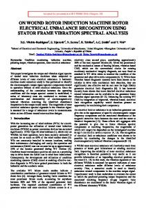
to the rotor wing as well. The con guration for our analysis is depicted on Figure 1, together with the subdivision into inner and outer regions. Consider rst the case of a xed wing. Far from the tip, the circulation in the inner (tip) region becomes constant and, to leading order, vorticity is not shed from the wing in that region. This observation explains the importance of the trailing vortices in the tip-region and their relative unimportance inboard for a xed wing. In the tip region where the circulation varies rapidly, the individual vortex laments would be expected to roll over each other to form the tip-vortex. In the case of the rotary wing, vorticity is shed inboard and the bound circulation assumes a more or less linear behavior away from the blade tip. Later we show that Stewartson's solution[13] applies to the rotary wing as well, except that the rotary wing equation for the bound circulation involves an additional parameter which is dependent on aspect ratio, angle of attack and number of blades. The formation of the tip-vortex is viewed here as a collection of individual vortex laments shed from discrete positions on the wing as a result of the spanwise variation of the bound circulation. The individual laments roll around each other to form the tip-vortex as depicted in the photograph on Figure 2 [14]; these streakline patterns show the behavior of trailing vortices shed from discrete positions; note that some of the vortex-like lines wrap from the underside. Such a lament-like structure for the tip-vortex is mentioned by Lanchester [15] in his book published in 1907, indicating a long history of this interpretation. Lanchester shows a tip-vortex as consisting of individual vortex laments winding around themselves to form the developed tip vortex downstream. The plan of the paper is as follows. After a discussion of the wake model, the lifting surface problem is formulated. It is then found that to leading order in aspect ratio, the blade appears semi-in nite in length. Horseshoe vortices are used to model the rotor blade 4
and wake (inner problem), while the helical vortex structure of the far wake (outer problem) is modelled as a cylindrical structure of vortex rings. The numerical results for the circulation compare very well with the analytical solution for the rotary wing, corresponding to the lifting line. Results are then presented for the roll-up structure of the tip vortex. Finally a computational model for wake contraction is presented. The computational results for the bound circulation compare well with the experimental data for the rotary wing.
Asymptotics of Lifting Line and Lifting Surface Theory for the Rotary Wing in Hover
The Lifting Line
The integral equation of lifting-line theory has been derived for the case of a xed wing in many text books. In particular, Ref. [16] gives ! Z b mc 1 2 d;� dy0� � � U � ; (1) ; (y ) = 2 1 0 4� ; 2b dy0� y� ; y0� where ;� is the circulation, �0 is the geometric angle of attack, U1 is the speed far from the wing, b is the span of the wing, and c is the local value of the chord. Here m is a constant equivalent to the lift-curve slope which is airfoil dependent. For a at plate, m = 2�. In the general case, both c and �0 may depend on y. It is important to understand the assumptions of linearized theory associated with the derivation of this equation. Of principal importance for our purposes are 1. the trailing wake is assumed to remain in the plane of the wing z = 0 for all time, or equivalently in linearized theory, in the cross-plane containing the freestream velocity vector; and 2. the pressure di�erence between the bottom and the top of the wing must approach zero at the tip, and so ;� = 0 there also. 5
However, for a rotary wing, the trailing vortices are driven downward away from the rotor-tip path plane and form a more-or-less helical wake. Therefore, the assumption that trailing vortices remain in the rotor-tip path plane as for the xed wing is not valid and the lifting line Eqn. (1) can not be applied to the rotor-tip directly. Including the in uence of the helical rotor wake, it is shown here that in the tip region, to leading order, the bound circulation of the rotary wing has a solution similar to that of a xed wing, although the rotary wing analysis involves a parameter dependent on the aspect ratio, the angle of attack and the number of blades. We have applied the results of vortex theory together with the concepts of Prandtl's lifting-line theory to describe the interaction between an assumed cylindrical slipstream and the bound circulation for an n-bladed rotor operating in hover (static thrust). In Prandtl's theory, the high aspect-ratio wing is represented by a line vortex (the lifting line) and the aerodynamic properties of each spanwise section are approximated locally by the two-dimensional characteristics from linearized airfoil theory. However, the free stream of the local section is replaced by the relative wind, i.e., the e�ective angle of attack is the geometric angle of attack reduced by the local downwash induced by the trailing vortices. For the case of the rotor blade in hover, two modi cations must be made:
� the true free stream in wing theory is replaced by the angular velocity of rotation of the blade, and
� the trailing vortices of the rotor follow a more-or-less helical path. Corresponding to the variation of bound circulation, vortices are shed all across the rotor, forming an approximately cylindrical slipstream lled with concentric helical vortices. These discrete helical vortices are approximated by uniform cylindrical sheets of vorticity. 6
For purposes of computing the downwash, these elemental vortex cylinders may be viewed as composed of vortex rings, whose strength is approximately constant on each cylinder. The axial component of the helical vortices, that is, the component of the circulation oriented in a direction normal to the tip-path plane may be ignored for present purpose, since it does not contribute to the downwash. A cylindrical coordinate system (r; �; z) is convenient, where r is the radial coordinate, � the azimuthal coordinate, z the axial coordinate (see Figure 3, which illustrates a single vortex cylinder). These elemental vortex cylinders, formed from the inboard vortex sheet, are superposed with the vortex cylinder generated by the tip-vortex to form the complete rotor slipstream. Unlike the apparently simpler case of the xed wing, simple analytical formulas have been derived for rotor aerodynamics. Knight and He�ner[17] based their derivation on vortex theory, discussed above, while Gessow and Myers[18] derive the same result on the basis of Glauert's[19] simple momentum theory. In either case, the results are shown to depend on a single parameter � = ��nc0a where a is the blade-tip radius and n is the number of blades. For the case of a rectangular blade the induced downwash has the form
p W (R) = va�z = 41� ( 1 + 8�R ; 1) 0
(2)
where W (R) is the nondimensional downwash, and R = r=a. We have introduced the parameter � to account for the varying pitch of the helical vortex loops along the assumed cylindrical slipstream. Knight and He�ner have taken � = 2, corresponding to conditions either just inside the slipstream boundary, or at in nity on the boundary itself, whereas 7
� = 1 corresponds to conditions on the slipstream boundary just below the rotor. We have chosen � = 1 as more appropriate for evaluating the bound circulation on the rotor. It is easy to see that the induced downwash W (R) increases monotonically, from zero at the hub to a maximum value at the tip, the latter value depending on the parameter �. Eqn. (2) shows as � ! 0, W (R) has a linear spanwise distribution. Also W (R) vanishes as � ! 1 (in nite blade-aspect ratio) and thus in this case, the rotary wing is equivalent to a semi-in nite wing. The blade circulation is given by � ; = ;ac = ��0 [R ; W (R)]
(3)
This outer solution, described above, is not valid near the rotor tip and proper treatment of this irregularity requires consideration of the inner expansion. Consider the ow in the tip region shown on Figure 1. In the tip region, the most recently shed trailing vortices can be approximated as straight lines because here the curvature of the trailing vortices is much less than the length scale c. Therefore, their in uence is represented by the integral term in Eqn. (1). However, di�erent from the xed-wing case, the previously shed vortices do not remain in the rotor tip-path plane; instead, they are driven downward away from the rotor tip-path plane and form the helical rotor wake. Therefore, the in uence of the helical rotor wake needs to be considered in Eqn. (1). First, we replace U1 and y� in Eqn. (1) with r and r respectively, and nondimensionlize Eqn. (1) by writing R = ar . Hence ;1 ;(R) = mC2(R) �0R ; A4�
1
Z
0
d; dR0 dR0 R ; R0
!
where C (R) = 1 for a rectangular rotor and ; has been de ned previously. 8
(4)
To focus on the tip region, we make the transformation Y = (1 ; R)A where is a constant. Substituting Y into Eqn. (4), we nd to balance both sides, = 1. If we assume that ; remains O(1) near the rotor-tip, and the chord nite at the wing-tip, then ; may be expanded as ; = ;1 + O(A;1). Substituting into Eqn. (4), the leading-order terms of the lifting-line integral equation for a semi-in nite wing are found, as Z 1 1 d;1 dY0 ) m (5) ;1(Y ) = 2 (�0 ; 4� 0 dY0 Y ; Y0 For the helical rotor wake, the correction to the downwash in the tip region, caused by the wake, must be included in Eqn. (5). There results " # Z 1 m 1 d ; 1 dY0 ;1(Y ) = 2 �0 ; 4� ; �0 W (Y ) (6) 0 dY0 Y ; Y0 where W (Y ) is the downwash induced by the helical rotor wake in the inner region. Expanding the outer solution for the downwash in the rotor-tip path plane W (R) in Eqn. (2) with the inner variable Y = 1A;;R1 , we nd that to leading order as A ! 1 p (7) W0(Y ) � 14+� 8� ; 41� Substituting W0 (Y ) into Eqn. (6), we have p " # Z 1 m 1 1 d ; 1 + 8 � 1 dY0 ;1 (Y ) = �0 (1 ; + ); (8) 2 4� 4� 4� 0 dY0 Y ; Y0 Comparing Eqn. (8) with the leading-order equation for a xed wing, it is easy to see that to leading order, the only di�erence is the appearance of a constant parameter p D = 1 ; 14+� 8� + 41� which contains the wake information. Therefore, to leading-order, in the tip region, a rotary wing is similar to a xed wing and thus Eqn. (8) has an analytical solution similar to that of Stewartson[13]. 9
Hence Eqn. (8) becomes ;1 (Y ) = m�20 D 1 ; 4��1 D 0 "
Let Y = m8 � , and let
Z
1 d;1
0
dY0 dY0 Y ; Y0
d�0 0 d�0 � ; �0 0 Hence for the leading-order inner solution, we have f (� ) = �m�2 D
Z
1 d;1
;1(Y ) = m�20 D [1 ; f (� )]
#
(9) (10)
(11)
and from Eqn. (10) above, the solution is obtained in the same form as that of Stewartson [13]; i.e., Z 1 ;t � 1 R t log�d� 1 e ; � f (� ) = � e 0 1+�2 dt (12) 0 (1 + t2 )3=4 We call Eqn. (11) the modi ed Stewartson's solution since it is identical to his analytical solution aside from the parameter D. Since the bound circulation directly in uences the subsequent position of the tip-vortex and the intensity of the subsequent interactions with other components of the wake, it is important to determine the circulation as precisely as possible. In the next section, we use lifting-surface theory to evaluate the inner solution, valid near the rotor tip and compare the results with our lifting-line theory.
The Lifting Surface
Following the work of Falkner[20] and of Schlichting and Thomas [21], the semi-in nite wing may be represented by vortex panels distributed over its surface, as illustrated on Figure 4 (a). For clarity, in Figure 4 (a), only three chordwise panels and nine spanwise panels including semi-in nite panels (discussed below) are shown, while in the numerical calculation, ten chordwise and twenty spanwise panels were used. Each wing panel consists 10
of a horseshoe vortex system with a bound vortex along the panel quarter-chord line together with trailing vortices lying along the panel edges, extending through the trailing edge of the wing and moving with the local velocity after leaving the trailing edge of the wing. Figure 4 (b) shows a wing surface panel represented by a horseshoe vortex. We now de ne local panel-based coordinates; de ne the x-axis to be oriented in the chordwise direction, the y-axis spanwise, and the z-axis vertical as shown in Figure 4 (b). x0 and y0 are measured from the midpoint of the selected panel, and z from the plane of the wing. The panel-width dimensions are 2a by 2b in the chordwise and spanwise directions respectively. Then the velocity induced by each horseshoe vortex segment is evaluated using Biot-Savart law. The velocity induced by the bound-vortex segment is
uB (x0; y0; z) = 41� (x0 + az)2 + z2 � 2 0 [ 0 a 2y + b0 2 2 (x + 2 ) + (y + b) + z 0 ; 0 a 2y ; b0 2 2 ] (x + 2 ) + (y ; b) + z q
q
x0 + a wB (x0; y0; z) = ; 41� (x0 + a )2 2+ z2 � 2 0 [ 0 a 2y + b0 2 2 (x + 2 ) + (y + b) + z 0 ; 0 a 2y ; b0 2 2 ] (x + 2 ) + (y ; b) + z q
q
while the two unit trailing vortices produce the contributions
vT1 (x0; y0; z) = 41� (y0 + bz)2 + z2 � x0 + a [ 0 a 2 20 2 2 + 1] (x + 2 ) + (y + b) + z q
11
0 wT1 (x0 ; y0; z) = ;4�1 (y0 +y b+)2 b+ z2 � x0 + a [ 0 a 2 20 2 2 + 1] (x + 2 ) + (y + b) + z q
and
vT2 (x0 ; y0; z) = ;4�1 (y0 ; bz)2 + z2 � x0 + a [ 0 a 2 20 2 2 + 1] (x + 2 ) + (y ; b) + z q
0 wT2 (x0 ; y0; z) = 41� (y0 ;y b;)2 b+ z2 � x0 + a [ 0 a 2 20 2 2 + 1] (x + 2 ) + (y ; b) + z where u, v and w are the x, y and z components respectively. Subscript B designates the bound-vortex segment and T1 , T2 designate the two trailing vortices. Now we consider the global coordinates; de ne the x-axis to be oriented in the chordwise direction, originating at the leading egde of the wing, the y-axis spanwise, originating at the wing-tip, and the z-axis vertical, as shown on Figure 4 (a). The panel-in uence coe�cients Akj are given by the normal velocity induced in the plane of the wing at the 3=4 chord position on panel k due to the horseshoe vortex of unit circulation with the bound vortex at the 1=4 chord position on panel j , as q
Akj = wB (xkj ; ykj ; 0) + wT1 (xkj ; ykj ; 0) + wT2 (xkj ; ykj ; 0) where xkj = xk ; xj + a2 and ykj = yk ; yj . Note xk , xj , yk , yj are global variables and xkj , ykj are the local variables, x0 ; y0, above. The boundary condition of zero normal velocity on the wing surface is satis ed at the three-quarter chord point on the centerline of each panel, as in Schlichting and Thomas[21], 12
and the vortices emanate from the panel quarter-chord line and extend through the trailing edge of the wing to in nity downstream (see Figure 5). Thus the panel circulations ;k ; k = 1; :::; N may be evaluated from the surface boundary condition, expressed as the linear equation N X Akj ;j = ;w1 j =1
For a at-plate airfoil, the right side vector w1 is just the vertical component of the freestream velocity vector reduced by the leading order-inner downwash induced by the helical rotor wake; i.e., U1�0 (1 ; W0 (Y )) in linearized theory. For the numerical computation, the semi-in nite wing is represented by a nite number of panels outboard of a semi-in nite panel. The baseline con guration uses twenty chordwise panels and forty spanwise panels. The semi-in nite panels have been applied beyond the fortieth spanwise panel at each chordwise location to model the semi-in nite aspect of the problem. Each of the semi-in nite panels has only one bound vortex and one trailing vortex, i.e., half of a horseshoe vortex. The bound vortex extends to in nity spanwise and the trailing vortex extends to in nity downstream as shown on Figure 4 (a). The boundary condition of nite circulation at in nity is represented by requiring the values of bound circulation of each of the semi-in nite panels to be equal to those of the panels next to them. The velocities induced by the leading bound-vortex segment of the semi-in nite panel are uB1(x; y; z) = 41� (x + az)2 + z2 � 2 y+b ] [1 ; q a (x + 2 )2 + (y + b)2 + z2
x + a2 1 wB1(x; y; z) = ; 4� (x + a )2 + z2 � 2 y+b [1 ; q ] a (x + 2 )2 + (y + b)2 + z2 13
The trailing vorticity becomes small at a distance of the order of a chord length from the wingtip. Hence accurate computation of the trailing vorticity requires a strong concentration of the horseshoe-vortex panels in the region near the wingtip. Consequently it is helpful to use panels of variable width. We have chosen the variation
y = �b tan �; 0 < � < �=2 where �b is the computational span of the semi-in nite wing. Thus distributing the panels uniformly in the � variable increases the physical density of panels near the wingtips. A constant chordwise width was used for each panel, since varying panel width was found to be less important in the chordwise variable x. Figure 6 shows the e�ect of the number of panels used in the lifting surface code. Note that the comparison is good. This suggests that ten chordwise panels and twenty spanwise panels are su�cient for the computations. Figure 7 shows the results of the lifting-surface computation for the bound circulation near the rotor-tip. Note the excellent comparison of the numerical results with the modi ed formula of Stewartson[13], Eqn. (11). In the region of sharp drop-o� of the bound circulation, the individual vortex laments will roll around each other to form the tip-vortex. In the region away from the tip, where the circulation approaches a constant, no trailing vorticity is shed to leading order. Comparisons between lifting line and lifting surface models for a nite length rotor blade have been presented by Kocurek et al. [22]; they nd that lifting line theory overpredicts the torque coe�cient at large thrust coe�cient. Having described the model for the rotor blade, we can calculate the positions of the shed vortices behind the rotor blade. The amount of trailing circulation is determined by the derivative of the bound circulation and in discrete form the trailing circulation at a xed 14
radial location in the inner region near the blade tip is ;B ;t = ; ddY
(13)
In a steady inviscid- ow eld, the trailing vortex lines are also streamlines. Therefore, we can obtain the positions of vortex lines by solving the set of equations
dY = V dx 0
(14)
dz = � (1 ; W (Y )) (15) 0 dx 0 where we have linearized the right hand side of each equation about the dimensionless free stream speed. Here (x; Y; z) are global coordinates, with x measured from the leading edge and non-dimensionalized by the chord. Here x is the independent variable measured from leading edge of the wing. The vortices are initiated at the one-quarter chord position of each panel at the beginning of the numerical integration for every iteration. For the initial condition, z = 0 and Y is the spanwise location of the trailing vortex shed from the onequarter chord of each panel. The trailing vortices are forced to stay on the wing surface up to the trailing edge of the wing but can be displaced in the Y direction by the induced velocity, unlike the previous work of the present authors [23]. This set of ordinary di�erential equations was solved numerically by the Adams-Moulton method. Note that the velocity components were calculated for straight-line trailing vortices in the rst iteration. In order to obtain the initial positions of the trailing vortices, we introduce three parameters to describe the roll-up process. They are Y� , z� which are the Y and z components of the center of the tip-vortex core and r� which de nes the core radius measured from the centroid. We de ne 15
Y� = z� =
n PM ; Y k=1 j =1 t;jk jk Pn PN k=1 j =1 ;t;jk
(16)
n PM ; z k=1 j =1 t;jk jk Pn PN k=1 j =1 ;t;jk
(17)
P
P
where n is the number of trailing vortices which are rolling over each other, M is the number of chordwise panels and ;jk is the circulation of the panel (j , k). The core radius r has been de ned as v uP n PM (Y� ; Y )2 + (� u z ; zjk )2 jk t k=1 j =1 r� = (18) n�N The iterative process was assumed to be convergent when r�newr�old;r�old is less than 10;4 at each given value of x. Here we have used one chordwise panel, twenty spanwise panels on the wing surface and one hundred and twenty nodes on each of the trailing vortices. The separation between the nodes on each of the trailing vortices is 0:05. Beyond the last node, the trailing vortex is represented by a semi-in nite, horizontal straight vortex line extending to x = +1 and parallel to the free-stream velocity.
A Simple Contraction Model
A simple model for the slipstream contraction has been used to determine the e�ect of contraction on the bound circulation. In this model, the slipstream has been modelled by a piecewise-continuous sequence of vortex cylinders having di�erent ( nite) lengths li and radii ai . The cylinders are distributed both radially and axially to give a discretized representation of the continuous distribution of vorticity in the rotor slipstream. The contraction ratio of successive vortex cylinders is represented by the variable �i = ai+1=ai; i = 1; :::; N , with �i < 1. The rst vortex cylinder, i = 1, originates in the rotor tip-path plane z = 0, and has radius a equal to that of the rotor. The last vortex cylinder, i = N , extends downwards to in nity. Thus the overall contraction ratio is aN =a1. 16
For this model, the lifting-line model was solved by a numerical scheme, using the ellipticintegral formulas below to evaluate the downwash induced by each vortex cylinder. The slipstream con guration used in the computations, shown in Figure 10, is composed of thirty vortex cylinders. The axial velocity induced by a cylinder of radius r0 and length (zi+1 ; zi ), composed of vortex rings of azimuthal vorticity � i, may be written as follows (Radcli�, et al [24]): 8
0 (r; z ; r0 ; z ; z
vz i
i i+1 ) =
0 z ; zi r ; r 2; k ) K ( k ) ; �( � i;i i i;i 0 r+r (z ; zi)2 + (r + r0)2
� i(r0) < q 2�
:
"
#
#9 =
z ; zi+1 r ; r0 �(� 2; k ) (19) ; K ( k ) ; i;i+1 r + r0 i i;i+1 (z ; zi+1 )2 + (r + r0)2 Here K is the complete elliptic integral of the rst kind and � is the complete elliptic integral of the third kind. The moduli of the elliptic integrals are de ned as "
q
;
0
kij 2 = (r + r0)24+rr(z ; z )2 j
and
0 �i 2 = (r 4+rrr0)2
For the uncontracted slipstream, the vortex cylinder is semi-in nite in length. For this limit the following properties of the elliptic integrals are convenient:
K (0) = �=2;
p
�(�2; 0) = �=2 1 ; �2 ;
�(�2 ; �) = E (�)=(1 ; �2)
Hence in the limit zi ! 0; zi+1 ! 1, Eqn. (19) yields the following result for the axial velocity induced by the uncontracted slipstream:
a �(�2; k) vz (r; z) = 4� [1 + Sign(a ; r)] + �2 (r + az)2 + z2 K (k) ; rr ; +a (
�
17
�)
(20)
This result may be used also for the nal vortex cylinder of the contracted slipstream model by replacing r by aN and z by z ; zN . The induced axial velocity for all elementary vortex cylinders, both axially and internally (across the slipstream), is obtained by integrating that for a single cylinder, Eqn. (19), with respect to r0 from the axis to the slipstream boundary r = ai , and summing with respect to i over all axial cylindrical segments:
vz (r; z) =
N
X
Z
i=1 0
ai
vz 0i(r; z; r0; zi; zi+1 ) dr0
The azimuthal vorticity i is equivalent to the strength of the circulation shed from the rotor divided by the axial distance the shed vortex advances in one turn of the rotor. Denote the physical value of the circulation of the shed vortices by ;�w . Then for small helix angle, � ; w �
� i = ;w =(vz � �t) = 2�v 0 (21) z r=r Since the circulation of each of the vortex \helices" is constant along the whole length of the slipstream, � varies inversely with vz . Since the elementary slipstreams are streamtubes, this implies that � is proportional to the local radius of the slipstream. Hence the ratio of vorticity of successive vortex cylinders is just
� i+1 = ai+1
� i ai and this result holds for each internal vortex cylinder as well. The azimuthal vorticity of the uppermost vortex cylinder can be evaluated in terms of the downwash in the rotor path plane as follows. For a thin uncambered airfoil section, the lift coe�cient is given by Cl = 2��, where � is the local angle of attack with respect to the relative wind; i.e., � = �0 ; vz = r. Then from the Kutta-Koukowsky theorem, the blade circulation is given by ;� = �c[ �0 r ; vz ] 18
The circulation shed from the blade at radius r, per unit span, is ;�w = Eqn. (21) the azimuthal vorticity becomes
� 1 = 2ac W1 1 ; dW dR "
d;� , dr
so that from
#
where the non-dimensional variable R and W have been de ned previously in the lifting line section. If the downwash is approximated by Eqn. (2), then the azimuthal vorticity of the uppermost vortex cylinder is given by
� 1 = 2 ac� � p 1 1 + 8�R The streamtube induced by the semi-in nite (uncontracted) vortex cylinder provides a convenient approximation for the shape of the contracted slipstream. The coordinates of the streamtube were obtained by integrating the equation for its slope:
dr = vr dz vz where the radial and axial components of velocity are obtained from elliptic-integral formulas corresponding to Eqn. (20), as given by Radcli�, et al [24]. The results closely t the exponential approximation R = R1 + (1 ; R1)e;Z=Z1 where R1 = 0:729 and Z1 = 0:4254. Note that R and Z are normalized by the rotor tip radius, as de ned previously in the lifting line section. In the calculations, the radii ai of the outermost vortex cylinders were evaluated from this exponential approximation.
Results No Wake Contraction 19
In this section, results will be presented rst for the bound circulation and then for the rollup process. As mentioned, we solve for the bound circulation on the rotor by the method of matched aymptotic expansion. We use \mutiplicative composition", as de ned by Van Dyke[12], to form the uniformly-valid solution for the bound circulation ;uniform = ;inner;� ;outer (22) cp where ;inner is the inner solution of the bound circulation (near the tip region) given by the modi ed Stewartson[13] or the lifting surface code, ;outer is the outer solution[26] and ;cp is the common part, which is de ned as the bound circulation evaluated either in the limit as the outer variable R ! 1 or as the inner variable Y ! 1. The parameters of the rotor are are chosen to correspond to the parameters of McAlister et al[10] and are given in Table 1. Figure 9 (a) and (b) presents the x ; Y and x ; z views of the roll-up process for the rotor which converges up to x = 30. The vortex lines emanating from each panel are shown here. The direction of U1 relative to the rotor blade is indicated. Note that the trailing vortices near the tip region roll over and form a strong trailing vortex. However, in the region away from the tip, the trailing vortices do not roll up in distances of the order shown here. The tip-vortex is also shown to have moved inboard. The 3-D view is presented on Figure 10. Figure 11 shows the growth of the circulation of the tip-vortex as a function of x. The circulation of the tip-vortex is obtained by summing the circulations of each of the individual laments. The symbol 'o' in Figure 11 is the solution using four chordwise panels. For the rotor at �0 = 8o seen in Figure 11(a), as we go farther downstream and the iteration process is converged to x = 30, the circulation of the tip-vortes has reached 79% of the maximum bound circulation. The symbol '*' in Figure 11 denotes the solution for a single chordwise panel which is very close to four panel case. Clearly one panel is su�cient for design purposes, 20
a big savings in computational cost. Figure 12 shows the downstream development of the core radius r� of the tip-vortex measured from the centroid for angle of attack 8o. The core radii r� in Figure 12 were calculated at each downstream location x at which an additional trailing vortex enters the rolling-over trailing vortices. Note that the r� develops downstream and approaches a constant asymptotically. Figure 13 (a) and (b) show the x ; Y and x ; z views of the roll-up process for a rotor with �0 = 12o. A single chordwise panel was used in this case. The core radius is converged out to x = 30 and note that the center of the core has moved Figures 14 (a) and (b) show the x ; Y and x ; z views of the roll-up process for the rotary wing at �0 = 12o with four chordwise and twenty spanwise panels. Note that trailing vortices shed from di�erent chordwise panels but from the same spanwise location roll into the single strong tip-vortex at di�erent downstream locations. The trailing vortices that emanate from the panels closer to the leading edge of the rotor blade roll into the tip-vortex more quickly. The 3-D view is shown on Figure 15. Table 2 shows the comparison of the circulations of the tip-vortex for di�erent xed and rotary wings. At the same angle of attack and downstream location, the tip-vortex shed from a xed wing[23] is stronger than that for a rotary wing; that is, the xed wing tip-vortex develops more quickly than the rotor tip-vortex. Morever, the tip-vortex shed by the wing at higher angle of attack also develops more quickly than that shed by the wing at lower angle of attack. Such a di�erent downstream development is attributed to the di�erent spanwise variation of the bound circulation near the tip region: a steeper spanwise gradient produces stronger tip vortices and hence a quicker development of the tip-vortex. Figure 16 compares the numerical results for the vertical velocity with the more recent 21
experimental data of McAlister et al.[25] at a position 3 chord lengths behind the trailing edge of the rotor. The comparison is surprisingly good although the spanwise location of the maximum positive velocity occurs inboard of the experimental result.
The E�ect of Contraction
Consider the downwash induced by the rotor-wake contraction in the inner region where R � 1. Li[26] has evaluated the in uence of contraction on the value of the downwash and the maximum deviation from the uncontracted value is 8% for � = 0:07 and only 5% for � = 7. This in uence may be signi cant from the point of view of blade loading and design but for the present fundamental study, the in uence is considered minor. Consequently, in the results presented here, the in uence of contraction was only incorporated in the outer solution for the bound circulation away from the blade tip. Figure 17 compares the resulting uniformly-valid solution without slipstream contraction with the solution accounting for the rotor-wake contraction. Note that as � increases, the e�ect of slipstream contraction is reduced. This e�ect appears to be due to the reduction of induced downwash with increasing �. Figure 18 compares the current theoretical results with the experimental data of Caradonna and Tung [9]. The comparison is reasonably good in each case, though the peak value is underpredicted for the smallest value of angle of attack (�0 = 5o). For the large angle of attack (�0 = 12o), the wake contraction model produces better results than the model without wake contraction except near the tip.
Summary In this paper, we have developed a model for the aerodynamics of the formation of a rotary-wing tip-vortex based on vortex-dynamics considerations. The ow near the tip of 22
a large aspect-ratio rotary wing is equivalent to the ow past a semi-in nite xed wing with appropriately modi ed free stream and the incorporation of a suitable wake model. We have presented results for the bound circulation on the wing and for the subsequent rollup and formation of the tip-vortex downstream of the blade tip. Following the work of Falkner[20] and Schlichting and Thomas[21] we have modelled the lifting surface as a distribution of horseshoe vortices. The lifting surface results compare very well with the analytical solution of Stewartson [13] for the lifting line, suitably modi ed to account for the rotor wake. Moreover, the solution for the bound circulation does not seem to depend strongly on the number of panels in the chordwise direction and twenty spanwise panels is su�cient in the spanwise direction. In the tip region where the bound circulation varies rapidly, the individual vortex segments roll over each other and form a strong tip-vortex. The tip-vortex does not completely roll up near the rotor as assumed by many wake models; instead, the tip-vortex develops downstream and its circulation seems to be approaching a constant which appears to be signi cantly less that the maximum bound circulation. However, more work needs to be done to con rm this point. The results for the vertical velocity induced by the shed vorticity compared well with the experimental results of McAlister et al[10]. No turbulence model was necessary despite the fact that at the Reynolds numbers of the experiment, the ow would be expected to be turbulent. The numerical results for the bound circulation compare well with the experimental data from Caradonna and Tung[9] and the in uence of contraction within the inner region near the blade-tip appears to be of second order. Based on the comparisons with experimental data, there is little basis for the argument that the presence of turbulence has a signi cant e�ect on the structural properties of the tip-vortex. 23
Acknowledgements: This work has been supported by The US Army Research O�ce and monitored by Dr. Thomas L. Doligalski. The authors are grateful for his support during the course of this research. Thanks are due also to Dr. Ning Mei, Mr. Santosh Kini, and Mr. Vishwanath Godavarty who aided in preparing some of the gures.
References [1] Jain, Rohit, and Conlisk, A. T., \Interaction of Tip-Vortices in the Wake of a TwoBladed Rotor in Axial Flight," Journal of the American Helicopter Society, Vol. 45,(3), pp. 157-164, July 2000. [2] Kini, Santosh, and Conlisk, A. T., \The Development of Steady State Rotor Wakes," American Helicopter Society Aeromechanics Specialists' Meeting, Atlanta, Georgia, November 13, 14, 2000. [3] Tung, C., and Lee, S., \Evaluation of Hover Prediction Codes," Proceedings of the 50th Annual Forum of the American Helicopter Society, pp. 829-844, May 11-13, 1994. [4] Tung, C., Yu, Y., and Low, S., \The Aerodynamic Aspects of Blade/Vortex Interaction," AIAA 96-2010, June 1996. [5] Mahalingam, Raghav, \Experiments on the Origin of Tip Vortices," AIAA 2000-0278, 38th AIAA Aerospace Sciences Meeting and Exhibit, Reno, NV, January 2000. [6] Bhagwat, Mahendra J., and Leishman, Gordon J., \On the Ralationship between Blade Circulation and Tip Vortex Characteristics," 54th Annual Forum of the American Helicopter Society, May 20-22, 1998. 24
[7] Rule J.A., and Bliss D.B., \ Prediction of Viscous Trailing Structure from Basic Loading Parameters," AIAA J. Vol. 36, (2), pp. 208-218, Feb, 1998. [8] Cook, C. V., \The Structure of the Rotor Blade Tip Vortex," Paper 3, Aerodynamics of Rotary Wings, AGARD CP-111, Sept. 13-15, 1972. [9] Caradonna, F. X., and Tung, C., \Experimental and Analytical Studies of a Model Helicopter Rotor in Hover," NASA Technical emorandum 81232, September 1981. [10] McAlister, K. W., Schuler, C. A., Branum, L., and Wu, J. C., \3-D Measurements Near a Hovering Rotor for Determining Pro le and Induced Drag," NASA TP 3577, August 1995. [11] Van Dyke, M., \Lifting-Line Theory As a Singular Perturbation Problem," Arch. Mech. Stos, Vol. 16, (3), 1964. [12] Van Dyke, M., Perturbation Methods in Fluid echanics, Anotated Edition, Parabolic Press, 1975. [13] Stewartson, K., \A Note On Lifting Line Theory, Quart., Journ. Mech. and Applied Math., Vol. XIII, Pt. 1, pp. 49-56, 1960. [14] Head, M. R., In Flow Visualization II, W. Merzkirch, ed., pp. 399-403, Hemisphere, Washington, 1982. Also pg. 51 of Van Dyke, M., An Album of Fluid Motion, The Parabolic Press, Stanford, California. [15] Lanchester, F. W., Aerodynamics, 1907, quoted in Anderson, J.D., Fundamentals of Aerodynamics, Fig. 5.42, p. 366, 2nd Edition, McGraw-Hill, 1991. 25
[16] Katz, J., and Plotkin, A., Low - speed Aerodynamics: from Wing Theory to Panel Methods, McGraw - Hill, 1991. [17] Knight, Montgomery, and He�ner, Ralph A. \Static Thrust Analysis of the Lifting Airscrew," NACA TN 626, 1937. [18] Gessow, Alfred, and Myers, Garry C. Aerodynamics of the Helicopter. Macmillan Co., New York. 1952. [19] Glauert, H. \Airplane Propellers," Vol. IV, Aerodynamic Theory, Ed. by W. F. Durand, Julius Springer, 1935. [20] Falkner, V. M., \The Calculation of Aerodynamic Loading on Surfaces of Any Shape," Reports and Memoranda Aero. Res. Comm., London, no. 1910, 1943. [21] Schlichting, H., and Thomas, H. H. B. M., \Note on the Calculation of Lift Distribution of Swept Wings," Royal Aircraft Establishment Rpt., No. Aero. 2236, 1947. [22] Kocurek, J. David, Berkowitz, Lenard F., and Harris, Franklin D., \Hover Performance Methodology at Bell Helicopter Textron", Proceedings of the 36th Annual Forum of the American Helicopter Society, pp. 80-3-1 to 80-3-26, May 1980. [23] Li, Hui, Burggraf, O. R., and Conlisk, A. T., \On the Formation of a Tip-Vortex," AIAA paper 2000-0282, 38th AIAA Aerospace Sciences Meeting and Exhibit, Reno, NV, 2000. [24] Radcli�, T. D., Burggraf, O. R., and Conlisk, A. T., \On the Three-Dimensional Interaction of a Rotor-Tip Vortex with a Cylindrical Surface," J. Fluid Mech., Vol. 25, pp. 301-334, 2000. 26
[25] McAlister, K., Tung, C., and Heineck, J. T., \Devices that Alter the Tip Vortex of a Rotor", NASA/TM-2001-209625, AFDD/TR-01-A-003, 2001. [26] Li, Hui, \Formation of Rotor Tip Vortices," MSc. Thesis, Department of Mechanical Engineering, The Ohio State University, 2000.
27
List of Table Captions Table 1 The parameters for the rotor investigated by McAlister et al[10]. Table 2 The circulation of the tip-vortex for di�erent rotary wings. A two-bladed rotor of aspect ratio six and consisting of a single chordwise panel and twenty spanwise panels is used in each case.
28
List of Figure Captions Figure 1. Illustration of the inner and outer problems for the ow past a two-bladed rotor. Figure 2. Vortex wake of a xed wing as photographed by Head [14]. Figure 3. Vortex-cylinder coordinate system. Figure 4. (a) De nition of the global coordinates. Only three chordwise panels are shown here. (b) De nition of the local panel coordinates. The solid box represents a surface panel which is replaced by a horseshoe vortex (represented by dash lines). Figure 5. Schematic of the trailing vortex system. Open circles denote thequarter-chord location of each panel (bound vortices), solid circles denote panel edges. Arrows denote the normal direction at the panel three-quarter chord line (normal-velocity boundary condition). Figure 6. Comparison of the computational results with di�erent number of panels in the lifting surface code. Here `o' represents the computational results with ten chordwise and twenty spanwise panels and `+' represents the computational results with twenty chordwise and forty spanwise panels. Figure 7. Comparison of the inner solution for the bound circulation for a rotary wing between the lifting surface code and the modi ed Stewartson's equation (11) indicated by the solid line. The computational results are for ten chordwise and twenty spanwise panels. Figure 8. Exponentially shaped slipstream tted by cylindrical vortex segments. The spirals are for illustrative purposes only. Figure 9. Section view of the roll-up process of trailing vortices shed from the rotor. The core radius converges up to x = 30. The angle of attack is 8�; a single chordwise panel is used. (a) Plan view; (b) radial view. Figure 10. 3-D view of the roll-up process of the trailing vortices. The angle of attack is 8�; a single chordwise panel is used and the iteration process converges up to x = 30. 29
Figure 11. Evolution of the circulation of the tip-vortex. (a) Angle of attack is 8� and the maximum bound circulation is 0:153, the core radius has converged up to x = 30. A single chordwise panel is used. (b) Angle of attack is 12� and the maximum bound circulation is 0:274. * denotes a single chordwise panel; o, four chordwise panels. Figure 12. Evolution of the core radius r� of the tip-vortex measured from the centroid. The core radius has converged up to x = 30. A single chordwise panel is used and the angle of attack is 8�. Figure 13. Section view of the roll-up process of trailing vortices shed from the rotor. The core radius converges up to x = 30. The angle of attack is 12�; a single chordwise panel is used. (a) Plan view; (b) radial view. Figure 14. Section view of the roll-up process of trailing vortices for a rotary wing. (a) Plan view; (b) radial view. Four chordwise panels and twenty spanwise panels were used; the iteration process converges up to x = 30. The angle of attack is 12�. Figure 15. 3-D view of the roll-up process of the trailing vortices. The angle of attack is 12�; four chordwise panels and twenty spanwise panels are used; the iteration process converges up to x = 30. Figure 16. The vertical velocity in the rotor plane at x = 4, three chord lengths behind the trailing edge of the rotor. � denotes experimental data from McAlister[25] and |{, computational data. The rotor tip is at Y = 0 and inboard locations are for Y > 0. The angle of attack is 8�. Figure 17. Uniformly valid solutions with and without wake contraction for di�erent �. �0 = 8�. ....., without wake contraction; |{, with wake contraction. Figure 18. Comparison of the computational solutions with the experimental data of Caradonna and Tung for a two-bladed rotor. |{, numerical solutions with wake contraction; ....., numer30
ical solutions without wake contraction; +, experimental data for �0 = 12�; o, experimental data for �0 = 8� ; *, experimental data for �0 = 5�.
31
Table 1: The parameters for the rotor investigated by McAlister et al [10].
R 1.14m
R 132 m/s nb 2 Chord 0.191 m Attack angle 8o
Table 2: The circulation of the tip-vortex for di�erent rotary wings. A two-bladed rotor of aspect ratio six and consisting of a single chordwise panel and twenty spanwise panels is used in each case. ;tip Wing �0 x1 ;maxbnd Rotary1 8o 30 0.785 Rotary2 12o 30 0.815
32
Ω
Outer
y
x
Outer Inner
Inner
Figure 1: Illustration of the inner and outer problems for the ow past a two-bladed rotor.
33
Figure 2: Vortex wake of a xed wing as photographed by Head[14].
34
θ r
z Figure 3: Vortex-cylinder coordinate system.
35
Uoo
The Collocation point at three Quarter Chord Horseshoe vortex panel Y
X Bound vortex segment at one quarter chord line
Infinity
Semi−infinite panel with bound vortex segment and one trailing vortex
Trailing vortices shed from the one quarter chord of each panel
(a) Bound vortex at one quarter chord line
2b
y 2a x Collocation point at three quarter chord
Trailing vortex from one quarter chord line
(b) Figure 4: Horseshoe-vortex panel implementation of a semi-in nite wing. (a) De nition of the global coordinates. Only three chordwise panels are shown here. In the numerical calculation, ten chordwise panels are used. (b) De nition of the local panel coordinates. The solid box represents a surface panel which is replaced by a horseshoe vortex(represented by dash lines).
36
Figure 5: Schematic of the trailing vortex system. Open circles denote the quarter-chord location of each panel (bound vortices), solid circles denote panel edges. Arrows denote the normal direction at the panel three-quarter chord line (normal-velocity boundary condition).
37
λ → ∞o +
3
Γ * / Ω a c α0
2.5
2
1.5
1
0.5
0
+ o+ + o + +o+ o + o o+ ++ + o+ + o + + o+ o ++ +o ++ + o o + +++ + +o o +o o+ + ++ +o+ + o + ++o o + ++ o ++ o o ++o ++ + o+ o +o + ++ +o+ + + +o + +o o o + + o + +++ +o + o +++ +o o o + +o + + + o + ++ o + o+ ++ +++o +o +o o +o+ +o+ o + + o + + + o +o ++o o +++ ++ o o++o +++ ++ +o +o + + + + +o o +o ++ o +++o o +++ + + + o +++ o + o + + o + ++o+ +o+ + o+ ++o o ++o + o + + o + + o + ++ ++o ++o o ++ o o+ + 0
1
2
3
+o
+
10
+
o+
+
o+
+o
+
o+
+o
+
o+
+o
2 +o
1 0.5
0.1 +o
4
o+
+
5
6
7
8
Y
Figure 6: Comparison of the computational results with di�erent number of panels in the lifting surface code. Here `o' represents the computational results with ten chordwise and twenty spanwise panels and `+' represents the computational results with twenty chordwise and forty spanwise panels.
38
λ→∞
Γ * / Ω a c α0
3
2.5
10
2
2 1
1.5
0.5 1
0.1
0.5
0
0
2
4
6
8
Y Figure 7: Comparison of the inner solution for the bound circulation for a rotary wing between the lifting surface code and the modi ed Stewartson's equation (11). The solid line is the analytical solution of the modi ed Stewartson's equation. The circles are the computational results from the lifting surface code with ten chordwise and twenty spanwise panels.
39
Exponential Slipstream Fitted by Cylindrical Vortex Segment s 0 0.2 0.4 0.6
N
0.8 1 1.2 1.4 1.6 1.8 2 −1
−0.5
0 X
0.5
1
Figure 8: Exponentially shaped slipstream tted by cylindrical vortex segments. The spirals are for illustrative purposes only.
40
5
4
3
Y 2
1
0 0
5
10
15
20
25
30
20
25
30
X
(a) 4 3.5 3 2.5
Z
2
U∞
1.5 1 0.5 0
0
L.E T.E
5
10
15
X
(b) Figure 9: Section view of the roll-up process of trailing vortices shed from the rotor. The core radius converges up to x = 30:0. The angle of attack is 8�; a single chordwise panel is used. (a) Plan view; (b) radial view. 41
Wing surface
Roll-up Vortices ( Tip-vortex )
Weak inboard vortex
Figure 10: 3-D view of the roll-up process of the trailing vortices. The angle of attack is 8�; a single chordwise panel is used and the iteration process converges up to x = 30.
42
0.12
* * *
0.1
* *
0.08
* *
Γtip
0.06
* * * * *
0.04
0.02
0
0
5
10
15
20
25
30
X
L.E T.E
(a) 0.24
*
o
0.2
*
o
o
*o o* o*
0.16
*o
*o o * o * o * 0.08 o * o * 0.04 o *
Γtip 0.12
0
0
L.E T.E
o *
5
10
15
four chordwise panels single chordwise panel
20
25
30
X
(b) Figure 11: Evolution of the circulation of the tip-vortex. (a) Angle of attack is 8� and the maximum bound circulation is 0:153, the core radius has converged at x = 30. A single chordwise panel is used. (b) Angle of attack is 12� and the maximum bound circulation is 0:274. *, denotes a single chordwise panel; o, four chordwise panels. 43
0.225
*
0.2
*
0.175
*
0.15
-r
*
0.125
* 0.1 0.075
*
0.05
* *** *
0.025 0
0
L.E T.E
*
5
10
15
20
25
30
X
Figure 12: Evolution of the core radius r� of the tip-vortex measured from the centroid. The core radius has converged up to x = 30. A single chordwise panel is used and the angle of attack is 8�.
44
5
4
3
Y 2
1
0 0
5
10
15
20
25
30
20
25
30
X
(a) 4
3
Z
U∞
2
1
0
0
L.E T.E
5
10
15
X
(b) Figure 13: Section view of the roll-up process of trailing vortices shed from the rotor. The core radius converges up to x = 30 iterations. The angle of attack is 12�; a single chordwise panel is used. (a) Plan view; (b) radial view. 45
5
4
3
Y 2
1
0 0
5
10
15
20
25
30
20
25
30
X
L.E T.E
(a) 4
3
Z
U∞
2
1
0
0
L.E T.E
5
10
15
X
(b) Figure 14: Section view of the roll-up process of trailing vortices for a rotary wing. (a) Plan view; (b) radial view. Four chordwise panels and twenty spanwise panels were used; the iteration process converges up to x = 30. The angle of attack is 12�. 46
Wing Surface
Roll-up Vortices (Tip-vortex) Weak Inboard Vortex
Figure 15: 3-D view of the roll-up process of the trailing vortices. The angle of attack is 12�; four chordwise panels and twenty spanwise panels are used; the iteration process converges up to x = 30.
47
0.3
0.2
0.1
**** * * ** * * *** * * * * *** *
w/Uinf
* 0
****************************** ******* * * * ** * * * * * * * ** *
*
-0.1
-0.2
-0.2
0
0.2
0.4
0.6
0.8
1
1.2
Y
Figure 16: The vertical velocity in the rotor plane at x = 4 three chord lengths behind the trailing edge of the rotor. � denotes experimental data[25]; |{, computational data. The rotor tip is at Y = 0 and inboard locations are for Y > 0.
48
0.35
λ = 10 0.3
Γ*/Ωac
0.25
2
0.2
1
0.15
0.5
0.1
0.05
0
0
0.25
0.5
0.75
1
R
Figure 17: Uniformly valid solutions with and without wake contraction for di�erent �. �0 = 8�. ....., without wake contraction; |{, with wake contraction.
49
0.25
: with contraction ...: no contraction
0.2
+ : α0=12
Γ* / Ω a c
+
o : α0=8
0.15
+
+
o
+
o
* : α0=5
o o
0.1
o
o
+ o
*
o
0.05
*
*
*
* 0
0
0.1
0.2
0.3
0.4
0.5
0.6
0.7
0.8
0.9
1
R
Figure 18: Comparison of the computational solutions with the experimental data of Caradonna and Tung for a two-bladed rotor. |{, numerical solutions with wake contraction; ....., numerical solutions without wake contraction; +, experimental data for �0 = 12�; o, experimental data for �0 = 8�; *, experimental data for �0 = 5�.
50