May 2, 2015 - On using the Microsoft Kinect. TM sensors to determine the lengths of the arm and leg bones of a human subject in motion. M.J. Malinowskia, E.
arXiv:1505.00371v1 [physics.med-ph] 2 May 2015
On using the Microsoft KinectTM sensors to determine the lengths of the arm and leg bones of a human subject in motion M.J. Malinowski a, E. Matsinos∗ a a Institute
of Mechatronic Systems, School of Engineering, Zurich University of Applied Sciences (ZHAW), Technikumstrasse 5, CH-8401 Winterthur, Switzerland ∗
E-mail: evangelos[DOT]matsinos[AT]zhaw[DOT]ch, evangelos[DOT]matsinos[AT]sunrise[DOT]ch
Abstract The present study is part of a broader programme, exploring the possibility of involving the Microsoft KinectTM sensor in the analysis of human motion. We examine the output obtained from the two available versions of this sensor in relation to the variability of the estimates of the lengths of eight bones belonging to the subject’s extremities: of the humerus (upper arm), ulna (lower arm, forearm), femur (upper leg), and tibia (lower leg, shank). Large systematic effects in the output of the two sensors have been observed. PACS: 87.85.gj; 07.07.Df Key words: Biomechanics, motion analysis, treadmill, Kinect
1
Introduction
In a previous study [1], we established the theoretical background needed for the comparison of the output of measurement systems used in capturing data for the analysis of human motion. We developed our methodology for a direct application in case of the two versions of the Microsoft KinectTM (hereafter, simply ‘Kinect’) sensor [2], a low-cost, portable motion-sensing hardware device, developed by the Microsoft Corporation (Microsoft, USA) as an accessory to the Xbox 360 video-game console (2010). The sensor is a webcamera-type, add-on peripheral device, enabling the operation of Xbox via gestures and spoken commands. The first upgrade of the sensor (‘Kinect for Windows v2’), both hardware- and software-wise, tailored to the needs of
Xbox One, became available for general development and use in July 2014. In Ref. [3], we applied our methodology [1] to a comparative study of the two Kinect sensors and drew attention to significant differences in their output. Previous attempts to validate the Kinect sensor for various medical/healthrelating applications have been discussed in Ref. [1]. The present study is part of our research programme, investigating the possibility of involving (either of) the Kinect sensors in the analysis of the motion of subjects walking or running ‘in place’, e.g., on commercially-available treadmills. If successful, Kinect could become an interesting alternative to marker-based systems (MBSs) in capturing data for motion analysis, one with an incontestably high benefit-tocost ratio. Studied herein is the dependence of the evaluated lengths of eight bones of the subject’s extremities on the kinematical variables pertaining to the viewing of these bones by the sensor. The bones are: humerus (upper arm), ulna (lower arm, forearm), femur (upper leg), and tibia (lower leg, shank). The evaluated lengths of the subject’s left and the right extremities are separately analysed 1 . Ideally, the lengths of the bones of the subject’s extremities should come out constant, irrespective of the orientation of these bones in space and of the viewing angle by the sensor. In reality, a departure from constancy is inevitable, given that the Kinect nodes represent centroids in the probability maps obtained from the captured data in each frame separately [4]; as such, the node-extraction process is subject to statistical fluctuations and is affected by different systematic effects in the three spatial directions. In the present work, we first examine the variability of the evaluated bone lengths with the variation of two angles describing the orientation of the bones in space, to be denoted hereafter as θ and φ; θ is the angle of the bone with the vertical, whereas φ is the angle between the bone projection on the (anatomical) transverse plane and the z axis (the direction associated with the depth in the images obtained with the sensors). Subsequently, we investigate the dependence of the evaluated lengths of these bones on the inclination angle with respect to Kinect’s viewing direction. We pursue the determination of systematic effects in the Kinect-captured data, placing emphasis on establishing the similarities and the differences in the behaviour of the two sensors; in this respect, the present paper constitutes another comparative study of the two Kinect sensors, albeit from a perspective different to the one of Refs. [1,3]. The material in the present paper has been organised in four sections. In Section 2, we provide the details needed in the evaluation and in the analysis of the bone lengths. The results of the study are contained in Section 3. We discuss the implications of our findings in the last section. 1
The subject’s left and right parts refer to what the subject perceives as the left and right parts of his/her body.
2
2
On the evaluation and analysis of the bone lengths
In the original sensor, the skeletal data (‘stick figure’) of the output comprises 20 time series of three-dimensional (3D) vectors of spatial coordinates, i.e., estimates of the (x,y,z) coordinates of the 20 nodes which the sensor associates with the axial and appendicular parts of the human skeleton. While walking or running, the subject faces the Kinect sensor. In coronal (frontal) view of the subject (sensor view), the Kinect coordinate system is defined with the x axis (medial-lateral) pointing to the left (i.e., to the right part of the body of the subject being viewed), the y axis (vertical) upwards, and the z axis (anterior-posterior) away from the sensor, see Fig. 1. In the upgraded sensor, five new nodes have been appended at the end of the list: one is a body node, whereas the remaining nodes pertain to the subject’s hands. In both versions, parallel to the video image, Kinect captures an infrared image, which enables the extraction of information on the depth z. The sampling rate in the Kinect output (for the video and the skeletal data, in both versions of the sensor) is 30 Hz. As the Kinect output has already been detailed twice, in Sections 2.1 of Refs. [1,3], there is no need to further describe it here. The ‘upper’ endpoint (upper or proximal extremity) of each bone will be identified by the subscript S, the ‘lower’ endpoint (lower or distal extremity) by E. The upper and lower endpoints of the bones refer to the upright (erect) standing (rest) position of the subject (standard anatomical position); in this position, yS > yE in all cases. The four bones pertaining to the upper extremities (arms) are defined on the basis of the Kinect nodes SHOULDER LEFT, ELBOW LEFT, and WRIST LEFT (left side); SHOULDER RIGHT, ELBOW RIGHT, and WRIST RIGHT (right side). The four bones pertaining to the lower extremities (legs) are defined using the Kinect nodes HIP LEFT, KNEE LEFT, and ANKLE LEFT (left side); HIP RIGHT, KNEE RIGHT, and ANKLE RIGHT (right side). q
Denoting the bone length as L = (xS − xE )2 + (yS − yE )2 + (zS − zE )2 , the angle θ is estimated via the expression yS − yE ≡ ∆y = L cos θ .
(1)
Evidently, θ ∈ [0, π]; in the standard anatomical position, θ = 0◦ (ideally). Additionally, xS − xE ≡ ∆x = L sin θ sin φ (2) and zS − zE ≡ ∆z = L sin θ cos φ .
(3)
Obviously, φ = 0 when the bone projection on the transverse plane (x,z) −→ is antiparallel to the z axis (i.e., when the projection of the vector SE on that plane points in the direction of the sensor). Denoting the projected bone ◦
3
length on the transverse plane as Lxz = the relation:
q
(∆x)2 + (∆z)2 = L sin θ, we obtain
∆z (4) Lxz for all θ values, exempting θ = 0 and θ = π where the projected length Lxz vanishes; although cases in the data where θ comes out identical to 0 or π have not been found, we will assign (for the sake of mathematical completeness) the value of 0 to φ in both cases. Evidently, φ ∈ [0, 2π). In the present study, we will assume left/right symmetry (in the description of the motion of the bones) and restrict the angle φ in the [0, π] domain. cos φ =
Of relevance in the context of the present work is the angle at which the Kinect sensor views a bone. The inclination angle is obtained from the data as follows. Referring to Fig. 1, we define the position vectors pertaining to the bone endpoints as ~rS = (xS , yS , zS ) and ~rE = (xE , yE , zE ). The unit vector, normal to the KSE plane, is obtained via the expression: uˆN =
~rE × ~rS . k~rE × ~rS k
(5)
(We have not found instances in the data involving parallel or antiparallel vectors ~rS and ~rE .) The position vector of the midpoint M of the SE segment is given by ~rS + ~rE ~rM = (6) 2 and the unit vector along that direction by uˆR =
~rM . k~rM k
(7)
The unit vector uˆ, on the KSE plane, orthogonal to uˆR , is obtained by the expression uˆR × uˆN = uˆR × uˆN . (8) uˆ = kˆ uR × uˆN k −→ The inclination ω is the angle between SE ≡ ~rE − ~rS and uˆ; evidently, cos ω =
(~rE − ~rS ) · uˆ . k~rE − ~rS k
(9)
As we are interested in the inclination of each bone, not in its orientation with respect to the unit vector uˆ, we will use |cos ω| as free variable. It is expected that the reliability of the Kinect-evaluated bone lengths should increase with increasing |cos ω|. 4
3
Results
The data acquisition involved one male adult (ZHAW employee), with no known motion problems, walking and running on a commercially-available treadmill (Horizon Laufband Adventure 5 Plus, Johnson Health Tech. GmbH, Germany). The placement of the treadmill in the laboratory of the Institute of Mechatronic Systems (School of Engineering, ZHAW), where the data acquisition took place, was such that the subject’s motion be neither hindered nor influenced in any way by close-by objects. Prior to the data-acquisition sessions, the Kinect sensors were properly centred and aligned. The sensors were then left at the same position, untouched throughout the data acquisition. It is worth mentioning that, as we are interested in capturing the motion of the subject’s lower-leg parts (i.e., of the ankle and foot nodes), the Kinect sensors must be placed at such a height that the number of lost lower-leg signals be kept reasonably small. Our past experience dictated that the Kinect sensor should be placed close to the minimal height recommended by the manufacturer, namely around 2 ft off the (treadmill-belt) floor. Placing the sensor higher (e.g., around the midpoint of the recommended range of values, namely at 4 ft off the treadmill-belt floor) leads to many lost lower-leg signals (the ankle and foot nodes are not properly tracked), as the lower leg is not visible by the sensor during a sizeable fraction of the gait cycle, shortly after toe-off. The Kinect sensor may lose track of the lower parts of the subject’s extremities (wrists, hands, ankles, and feet) for two reasons: either due to the particularity of the motion of the extremity in relation to the position of the sensor (e.g., the identification of the elbows, wrists, and hands becomes problematic in some postures, where the Kinect viewing angle of the ulnar bone is small) or due to the obstruction of the extremities of the human body (behind the subject) for a fraction of the gait cycle. Assuming that these instances remain rare (e.g., below about 3% of the available data in each time series, i.e., no more than one lost frame in 30), the missing values may be reliably obtained (interpolated) from the well-determined (tracked) data. Although, when normalised to the total number of available values, the untracked signals usually appear ‘harmless’, particular attention was paid in order to ensure that no node be significantly affected. Five velocities were used in the data acquisition: walking-motion data were acquired at 5 km/h; running-motion data at 8, 9, 10, and 11 km/h. At each velocity setting, the subject was given 1 min to adjust his movements comfortably to the velocity of the treadmill belt. The Kinect output spanned slightly over 2 min at each velocity. The variation of the distance between the subject and the Kinect sensors was monitored during the data acquisition; it ranged 5
between about 2.5 and 2.9 m, well within the limits of use of the sensors set by the manufacturer. The recording on the two measurement systems started simultaneously. At each sampled frame, the bone lengths were calculated from the Kinect output and were histogrammed in (cos θ, cos φ) cells; the same values were also histogrammed in bins of |cos ω|. Twenty bins per angular direction were used in the former case, forty in the latter. Averages, as well as the standard errors of the means, were calculated in all cells/bins containing at least ten entries; cells/bins with fewer entries were ignored. Techniques yielding accurate results for in-vivo measurements of the human long bones include conventional (planar) radiography, CT scanning (e.g., see Ref. [5]), Raman spectroscopy [6], and ultrasonic scanning [7]. Unwilling or unable to use any of these techniques, we obtained static measurements of the subject’s bone lengths with an MBS (AICON 3D Systems GmbH, Germany) [8]. Our system features two digital cameras, a control unit, and a high-end personal computer (where the visualisation software is installed). The MoveInspect Technology HF|HR reconstructs the 3D coordinates of the centres of markers (adhesive targets, reflective balls) which are simultaneously viewed by the two cameras; the typical uncertainty in the determination of the 3D coordinates of each marker centre is below 100 µm, i.e., negligible when compared to other uncertainties, namely to those pertaining to the placement of the markers and to skin motion. The bone lengths, not to be identified herein with the suprema of the distances of any two points belonging to the bones regarded as 3D objects, were defined as follows. • Humerus: from the centre of the humeral greater tubercle (‘coinciding’ with the Kinect shoulder node) to the humeral lateral epicondyle. As it is not straightforward to identify the centre of the humeral greater tubercles, flat markers were placed on the greater tuberosities and the resulting humeralbone lengths were reduced 2 by 39 mm. • Ulna: from just below the humeral medial epicondyle, on top of the humeral trochlea, to the ulnar styloid process. 2
The description of the algorithm, used in the determination of the 3D positions of the skeletal joints of the subject being viewed with Kinect, may be found in Ref. [4]. The ‘3D positions of the joints’ of Ref. [4] are essentially produced from the ‘3D positions of the projections of the joints onto the front part of the subject’s body’ after applying a ‘shift’ in depth (i.e., from the surface to the interior of the subject’s body), namely a constant offset (ζc ) of 39 mm (see end of Section 3 of Ref. [4]). We will assume that the same correction is also applied to the infrared image in the vertical (y) direction (and, albeit not relevant herein, also in the medial-lateral (x) direction), in order to yield the y (and x) coordinates of the shoulder joints. Therefore, when comparing it with the Kinect-evaluated humeral-bone length, the MBS-evaluated length will be reduced by ζc .
6
• Femur: from the centre of the femoral head to just below the femoral medial condyle, on top of the medial meniscus. As the identification of the centres of the femoral heads, using a non-invasive anthropometric technique, is neither easy nor accurate, we obtained the hip positions by following the indirect approach of Ref. [9], featuring four flat markers on the surface of the subject’s body (see Subsection 2.2 of Ref. [1]). The knee positions were identified in two ways: either using ∅14-mm reflective balls on top of the medial menisci and applying a correction (lateral shift) similar to the one applied in Ref. [9] or using plat markers on the patellae (knee caps) and applying a correction in depth (half of the width of the subject’s leg, at the knee level, in sagittal view); the two results were found almost identical. • Tibia: from just below the femoral medial condyle, on top of the medial meniscus, to the medial malleolus. All measurements were acquired in the upright position. The extracted values of the subject’s bone lengths are listed in Table 1. The average values, along with the rms (root-mean-square) values of the corresponding distributions, of the Kinect-evaluated bone lengths are shown in Table 2, separately for the two Kinect sensors. A noticeable difference between the two sets of values occurs in the femoral-bone lengths, the values of which come out, in all cases, significantly smaller when using the data of the upgraded sensor; this underestimation is equivalent to an effect between 1.69 and 2.42 standard deviations in the normal distribution. The quoted uncertainties in Table 2 are large, indicating that systematic effects come into play, thus suggesting further analysis of the bone lengths, in terms of the kinematical variables θ, φ, and ω. 3.1 Profile scatter plots of the bone lengths in (cos θ,cos φ) cells Walking and running motions have different signatures; the differences are both quantitative and qualitative: the ranges of motion in running are larger, generally expected to increase with increasing velocity; qualitatively, the walking motion is characterised by extended elbow joints, the running motion by flexed ones. This last dissimilarity affects the detection of the elbows and of the wrists at several postures in running motion, inevitably introducing systematic effects in the evaluation of the humeral- and ulnar-bone lengths. Our first study of the systematic effects in the evaluation of the bone lengths involved profile scatter plots in (cos θ,cos φ) cells. For convenience, the following definitions will be used in the short description of the results obtained in this part of the analysis. • Forward (ventral) placement of a bone corresponds to a position of its lower7
endpoint joint more proximal to the Kinect sensor than the mid-coronal plane; ‘very forward’ placement refers to cos φ > 0.9. • Backward (dorsal) placement of a bone corresponds to a position of its lower-endpoint joint more distal to the Kinect sensor than the mid-coronal plane; ‘very backward’ placement refers to cos φ < −0.9. In general, the walking motion is restricted to small θ values; only in the case of the ulna does the motion extend to θ ≈ 60◦ . The humeral-bone lengths came out cos φ-dependent; systematically smaller values were extracted in forward placement, larger in backward. Regarding the ulna, the θ domain is somewhat enlarged in very forward placement, when the elbow joint is (usually) flexed. Regarding the tibia, a significant dependence of the evaluated length on cos φ was seen in very backward placement; the effect was maximal around the most distal position of the ankle (with respect to the Kinect sensor), where the shank is not viewed sufficiently well by the sensor. Compared to walking motion, the domain of the θ values is significantly enhanced in running (as expected). The evaluated humeral-bone lengths were (again) found cos φ-dependent. Regarding the ulna, the cos φ values were large (restriction of the motion to very forward placement). For the tibial bones, the evaluated lengths in very backward placement were found to be significantly larger than those obtained elsewhere. Again, the largest bone lengths were extracted for large θ and φ values (large dorsal elevation of the lower leg), where the tibial bone is not viewed sufficiently well by the Kinect sensor. In all cases, the relative minimax variation dr = 2(M − m)/(M + m) (where M and m stand for corresponding maximal and minimal values, respectively) of the extracted values of the bone lengths was large. The dr ranges (over all velocities) were: for the humerus, 3-22% (original sensor) and 4-20% (upgraded sensor); for the ulna, 7-29% (original sensor) and 8-35% (upgraded sensor); for the femur, 4-13% (original sensor) and 7-17% (upgraded sensor); and for the tibia, 18-24% (original sensor) and 24-26% (upgraded sensor). Overall, the matching of the results between the two sensors in the case of running motion was not satisfactory; the values of Pearson’s correlation coefficient (on the dr values of the eight bone lengths at fixed velocity) showed a pronounced velocity dependence, ranging from 0.958 at 5 km/h to 0.260 at 11 km/h.
3.2 Profile histograms of the bone lengths in |cos ω| bins
The analysis described in the previous subsection is suggestive of the direction which the investigation must next turn to. In short, it appears plausible to assume that the goodness of the evaluation of the bone lengths does not depend separately on the angles θ and φ, but on another quantity, namely on the 8
viewing angle of the particular bone by the Kinect sensor. It is reasonable to expect that the accuracy in the evaluation of each bone length depends on the inclination of that bone with respect to the Kinect viewing direction; when a bone is viewed by the Kinect sensor at almost right angle, its length should be evaluated more reliably. The appropriate free variable in this investigation, |cos ω|, is obtained via Eq. (9). The results, obtained from the data analysis, are shown in Figs. 2, 4, 6, and 8 for the original sensor; in Figs. 3, 5, 7, and 9 for the upgraded sensor. We now discuss these plots. • Humerus. There can be little doubt that both Kinect sensors systematically underestimate the humeral-bone length regardless of the type of the motion (walking or running). Only in the case |cos ω| → 1 in the walkingmotion data are the estimates close to the results of the static measurements. All humeral-bone lengths obtained for |cos ω| → 1 in the case of the running-motion data agree well, and are about 65-75 mm short of the results of the static measurements. This discrepancy is due to the misplacement of the arm joints during running, in particular of the elbows, which are kept in flexed position throughout the gait cycle. Compared to the original sensor, the upgraded sensor generally yields slightly shorter humeral-bone lengths. • Ulna. In the data obtained with the original sensor, some left/right asymmetry in the results is visible. The range of variation of the ulnar-bone length was found maximal (about 10 cm) in the case of the original sensor, for the right ulna. Regarding the walking-motion data for |cos ω| → 1, the extracted values do not disagree with the results of the static measurements. • Femur. The femoral-bone length, obtained with the original sensor, is seriously overestimated in all cases. The hip positions are mostly responsible for this discrepancy. (In Ref. [3], we reported that the waveforms for the hips, obtained from the two versions of the sensor, do not match well.) • Tibia. In all cases, both sensors seriously overestimate the tibial-bone lengths for small viewing angles and underestimate them for |cos ω| → 1. The range of variation of the tibial-bone length was found sizeable, namely between 9 and 11 cm. On the other hand, a nearly monotonic behaviour is observed in Figs. 8 and 9, and the results from the walking- and the running-motion data generally appear to be consistent between the two sensors. It must be mentioned that the dependence of the bone lengths L on |cos ω| is expected to be monotonic. Visual inspection of Figs. 2-9 reveals that this is not always the case. One reason for the observed departure from a monotonic behaviour (yet not the only one) is that the inclination ω is estimated from the Kinect-captured data; systematic effects also affect this estimation. The results, reported in the present section, have also been checked against influences from ‘cross-talk’, which might be present in the output of the two 9
Kinect sensors. Both sensors use reflected infrared light in order to yield information on the depth in the captured images; one might thus argue that, in case of a simultaneous data acquisition, they distort one another’s recording. To clarify this issue, data (using the same subject and velocity settings) were acquired with the two measurement systems ‘serially’, first with the original sensor, subsequently with the upgraded one; in both cases, the second sensor was switched off (but was not removed from the mount). The differences to the results reported herein were inessential. Our conclusion is that the aforementioned discrepancies cannot be due to an interaction between the two sensors.
4
Conclusions
The present paper addressed one use of the output of the two Microsoft KinectTM (hereafter, simply ‘Kinect’) sensors, namely the evaluation of the lengths of eight bones pertaining to the extremities of one subject walking and running on a treadmill: of the humerus (upper arm), ulna (lower arm, forearm), femur (upper leg), and tibia (lower leg, shank). For comparison, static measurements of these bone lengths were obtained with a marker-based system. The evaluated lengths of the left and right parts of the subject’s extremities have been separately analysed. The constancy of the lengths of these eight bones in terms of the variation of the two angles involved in the viewing, θ of Eq. (1) and φ of Eq. (4), was examined. We have also investigated the dependence of the bone lengths on the inclination angle ω of Eq. (9) with respect to Kinect’s viewing direction. We pursued the analysis of systematic effects in the output, emphasising on the similarities and the differences between the two sensors; in this respect, the present study is another comparative study of the two Kinect sensors, albeit from a perspective different to that of Refs. [1,3]. The walking motion is characterised by extended elbow joints and small θ values in the case of the humerus and of the femur; in the case of the ulna, the θ values reached about 60◦ . The running motion is characterised by flexed elbow joints and (compared to the walking motion) extends more in θ. The motion of the ulnar bones is different in walking and running; in the latter case, the ulnar motion extends in θ, rather than in φ. A major overestimation of the tibial-bone lengths occurs in very backward placement, where these bones cannot be viewed sufficiently well by the Kinect sensors. The analysis of the arm-bone lengths in terms of the inclination angle ω demonstrated that the results obtained with both sensors do not agree well with those of the static measurements; agreement occurs only in the walkingmotion data for |cos ω| → 1, where the bones are viewed at almost right angle 10
by the sensor. We advanced an argument providing an explanation of this effect: it is mainly due to the systematic misplacement of the elbow nodes in the running motion, where this joint is kept in flexed position throughout the gait cycle. Regarding the leg bones, there is no doubt that the original Kinect sensor seriously overestimates the femoral-bone length. Both sensors overestimate the tibial-bone lengths for small viewing angles and underestimate them for large; discrepancies in the evaluated length of these bones lie in the vicinity of 9-11 cm, see Figs. 8 and 9. The present work corroborates earlier results [10], obtained with the original sensor (the upgraded sensor was not available at the time that study was conducted), that Kinect cannot be easily employed in medical/health-relating applications requiring high accuracy. In most cases, the results obtained with the two sensors disagree with the static measurements and show a large range of variation within the gait cycle. The determination and application of corrections, needed in order to suppress these artefacts, comprises an interesting research subject. Finally, we would like to comment on one misconception in the field of Medical Physics, namely that the results of studies using one subject, or only a few subjects, are not reliable. In our opinion, there are studies which call for statistics and studies in which statistics is superfluous. When comparing two measurement systems and the results (for a few subjects) come out sufficiently close, it does make sense to ‘pursue statistics’ and obtain reliable estimates of averages, standard deviations, and ranges. On the contrary, there are occasions (in particular, in the validation of measurement systems) where serious discrepancies are found in the output already obtained from the first subject. Unless one explains why the comparison of the output of the two measurement systems failed for that one subject, one subject is sufficient in invalidating the application! Even in case that the tested measurement system failed for the specific subject (and that it does not fail for the general subject), its validation must be performed for every future subject separately, to guarantee the validity of the output on a case-by-case basis; of course, this is not the essence of validations of measurement systems.
Acknowledgements
The original idea of investigating the subject of the present study belongs to S. Roth and M. Regniet, who (along with R. Jain) had conducted a similar analysis of data obtained with the original Kinect sensor. We are indebted to R. Guntersweiler and L. Lombriser for their support in the measurements obtained with the AICON system. 11
Fig. 1 has been produced with CaRMetal, a dynamic geometry free software (GNU-GPL license), first developed by R. Grothmann and recently under E. Hakenholz [11]. Conflict of interest statement The authors certify that, regarding the material of the present paper, they have no affiliations with or involvement in any organisation or entity with financial or non-financial interest.
References [1] M.J. Malinowski, E. Matsinos, S. Roth, On using the Microsoft KinectTM sensors in the analysis of human motion, arXiv:1412.2032 [physics.med-ph]. [2] http://www.xbox.com/en-GB/Kinect/, http://www.microsoft.com/en-us/Kinectforwindows/ [3] M.J. Malinowski, E. Matsinos, Comparative study of the two versions of the Microsoft KinectTM sensor in regard to the analysis of human motion, arXiv:1504.00221 [physics.med-ph]. [4] J. Shotton et al., Real-time human pose recognition in parts from single depth images, IEEE Conference on Computer Vision and Pattern Recognition (CVPR), June 20-25, 2011. [5] H. Siev¨anen et al., Peripheral quantitative computed tomography in human long bones: evaluation of in vitro and in vivo precision, J. Bone Miner. Res. 13 (1998) 871-882. [6] P. Matousek et al., Noninvasive Raman spectroscopy of human tissue in vivo, Appl. Spectrosc. 60 (2006) 758-763. [7] J. Litniewski et al., Ultrasonic scanner for in vivo measurement of cancellous bone properties from backscattered data, IEEE Transactions on Ultrasonics, Ferroelectrics, and Frequency Control 59 (2012) 1470-1477. [8] http://www.aicon3d.de, http://aicon3d.com/products/moveinspecttechnology/moveinspect-hf/at-a-glance.html ˜ [9] R.B. Davis, S. Ounpuu, D. Tyburski, J.R. Gage, A gait analysis data collection and reduction technique, Hum. Movement Sci. 10 (1991) 575-587. [10] A. Pfister, A.M. West, S. Bronner, J.A. Noah, Comparative abilities of Microsoft Kinect and Vicon 3D motion capture for gait analysis, J. Med. Eng. Technol. 38 (2014) 274-280. [11] http://db-maths.nuxit.net/CaRMetal/index en.html
12
Table 1 The values of the subject’s bone lengths (in mm), obtained from a marker-based system (see Section 3). To account for incorrect placement of the markers, an uncertainty of 10 mm is assumed in all cases, save for the femoral-bone lengths, where an overall uncertainty of 20 mm is applicable (linear combination of the placement uncertainty of 10 mm and of a 10-mm uncertainty representing the systematic effects of Ref. [9], as discussed in Section 2.2 of Ref. [1]). These values have been verified with a non-stretchable tape measure. Left humerus
343
Right humerus
344
Left ulna
258
Right ulna
271
Left femur
434
Right femur
436
Left tibia
434
Right tibia
427
13
Table 2 The average values of the subject’s bone lengths (in mm), separately for the two Kinect sensors. 5 km/h
8 km/h
9 km/h
10 km/h
11 km/h
Original Kinect sensor Left humerus
278(23)
249(22)
245(16)
249(16)
250(14)
Right humerus
284.1(6.1)
239(12)
240(13)
244(18)
247(15)
Left ulna
293(18)
271(27)
265(29)
253(24)
251(26)
Right ulna
277(15)
282(24)
268(24)
249(30)
251(30)
Left femur
531(29)
517(25)
513(30)
510(28)
503(30)
Right femur
519(23)
512(17)
512(25)
508(25)
506(30)
Left tibia
403(36)
431(35)
436(36)
440(38)
443(40)
Right tibia
418(30)
439(35)
445(37)
447(37)
451(36)
Upgraded Kinect sensor Left humerus
268(20)
241(10)
240.3(6.6)
243.3(7.4)
244.0(8.0)
Right humerus
273(10)
236(12)
235(13)
238(14)
239(14)
Left ulna
248(16)
253(30)
255(30)
244(28)
241(27)
Right ulna
253(11)
259(33)
246(30)
228(21)
230(23)
Left femur
409(42)
422(33)
428(39)
423(41)
419(40)
Right femur
427(35)
432(28)
438(34)
430(38)
418(41)
Left tibia
422(48)
420(41)
422(42)
423(44)
425(45)
Right tibia
409(48)
411(39)
415(40)
418(41)
428(42)
14
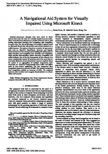
Fig. 1. The coordinate system of the Kinect sensor. The endpoints of the specific bone are identified as S and E. The angles θ and φ define the orientation of the bone in space, whereas the angle ω pertains to the Kinect view of the bone; when Kinect views the bone at right angle, ω = 0◦ . The (focal point of the) camera of the sensor appears in the figure as point K.
15
Right humerus
Left humerus
320
310
310
300
300
290
290
280
280
L (mm)
L (mm)
320
270
270
260
260
250
250
240
230
220 0.8
240
5 km/h 8 km/h 9 km/h 10 km/h 11 km/h 0.85
230
0.9
0.95
1
| cos ω |
220 0.8
5 km/h 8 km/h 9 km/h 10 km/h 11 km/h 0.85
0.9
0.95
| cos ω |
Fig. 2. The profile histogram of the humeral-bone length (separately for the leftand right-side bones) in |cos ω| bins; the data has been captured with the original Kinect sensor. In walking motion, the swinging of the right arm of the subject used in our data acquisition, is very small.
16
1
Right humerus
Left humerus
320
310
310
300
300
290
290
280
280
L (mm)
L (mm)
320
270
270
260
260
250
250
240
230
220 0.8
240
5 km/h 8 km/h 9 km/h 10 km/h 11 km/h 0.85
230
0.9
0.95
1
| cos ω |
220 0.8
5 km/h 8 km/h 9 km/h 10 km/h 11 km/h 0.85
0.9
0.95
| cos ω |
Fig. 3. The profile histogram of the humeral-bone length (separately for the leftand right-side bones) in |cos ω| bins; the data has been captured with the upgraded Kinect sensor. In walking motion, the swinging of the right arm of the subject used in our data acquisition, is very small.
17
1
Right ulna
Left ulna
320
340
310 320 300
290 300
L (mm)
L (mm)
280
270
280
260 260 250
240
5 km/h 8 km/h 9 km/h 10 km/h 11 km/h
230
220
0
0.2
0.4
5 km/h 8 km/h 9 km/h 10 km/h 11 km/h
240
0.6
0.8
1
| cos ω |
220
0
0.2
0.4
0.6
0.8
| cos ω |
Fig. 4. The profile histogram of the ulnar-bone length (separately for the left- and right-side bones) in |cos ω| bins; the data has been captured with the original Kinect sensor. In walking motion, the swinging of the right arm of the subject used in our data acquisition, is very small.
18
1
Right ulna
Left ulna
300
300
290
290
280 280 270
260
L (mm)
L (mm)
270
260
250
240
250
230 240
230
220
220
5 km/h 8 km/h 9 km/h 10 km/h 11 km/h 0
0.2
0.4
5 km/h 8 km/h 9 km/h 10 km/h 11 km/h
210
0.6
0.8
1
| cos ω |
200
0
0.2
0.4
0.6
0.8
| cos ω |
Fig. 5. The profile histogram of the ulnar-bone length (separately for the left- and right-side bones) in |cos ω| bins; the data has been captured with the upgraded Kinect sensor. In walking motion, the swinging of the right arm of the subject used in our data acquisition, is very small.
19
1
Right femur
Left femur
560
540
540
520
520 500
L (mm)
L (mm)
500
480
480
460
460 440 440
420
400 0.75
5 km/h 8 km/h 9 km/h 10 km/h 11 km/h 0.8
0.85
420
0.9
0.95
1
| cos ω |
400 0.75
5 km/h 8 km/h 9 km/h 10 km/h 11 km/h 0.8
0.85
0.9
0.95
| cos ω |
Fig. 6. The profile histogram of the femoral-bone length (separately for the leftand right-side bones) in |cos ω| bins; the data has been captured with the original Kinect sensor.
20
1
Right femur
Left femur
480
480
470 460 460
450 440
L (mm)
L (mm)
440
420
430
420 400 410
380
360 0.75
400
5 km/h 8 km/h 9 km/h 10 km/h 11 km/h 0.8
0.85
390
0.9
0.95
1
| cos ω |
380 0.75
5 km/h 8 km/h 9 km/h 10 km/h 11 km/h 0.8
0.85
0.9
0.95
| cos ω |
Fig. 7. The profile histogram of the femoral-bone length (separately for the leftand right-side bones) in |cos ω| bins; the data has been captured with the upgraded Kinect sensor.
21
1
Right tibia
Left tibia
500
500
480
480
460
440
L (mm)
L (mm)
460
420
440
420 400
5 km/h 8 km/h 9 km/h 10 km/h 11 km/h
380
360
0.4
0.6
5 km/h 8 km/h 9 km/h 10 km/h 11 km/h
400
0.8
1
380
0.4
0.6
0.8
| cos ω |
| cos ω |
Fig. 8. The profile histogram of the tibial-bone length (separately for the left- and right-side bones) in |cos ω| bins; the data has been captured with the original Kinect sensor.
22
1
480
460
460
440
440
L (mm)
L (mm)
Right tibia
Left tibia
480
420
400
400
5 km/h 8 km/h 9 km/h 10 km/h 11 km/h
380
360
420
0.4
0.6
5 km/h 8 km/h 9 km/h 10 km/h 11 km/h
380
0.8
1
| cos ω |
360
0.4
0.6
0.8
| cos ω |
Fig. 9. The profile histogram of the tibial-bone length (separately for the left- and right-side bones) in |cos ω| bins; the data has been captured with the upgraded Kinect sensor.
23
1