One Sensor Robot Control Technical report
Marinus Maris
Artificial Intelligence Laboratory Computer Science Department University of Zurich-Irchel Winterthurerstrasse 190 CH-8057 Zurich, Switzerland Tel: +41-1-257-4323 Fax: +41-1-363-0035 email:
[email protected]
December, 1994
Abstract
The robot Famez, a fast robot with a robust structure has been constructed to provide a flexible platform for studying autonomous agents. In this report, the robot is presented. Moreover, an obstacle avoidance control method involving only one (sonar) sensor is described. The main issue of the control scheme is that the robot has to find the proper steering direction to avoid an obstacle by utilizing its own motion. While moving and measuring the temporal derivative of the distance measurements, the robot acquires the appropriate steering information.
2
Contents Introduction ..................................................................................................................... 4 1. The hardware of Famez ............................................................................................ 5 1.1 Mechanics....................................................................................................... 5 1.2 Electronics ...................................................................................................... 6 1.3 Ultrasound detection .................................................................................... 7 1.4 Motor control ................................................................................................. 10 1.5 Steering ........................................................................................................... 11 1.6 List of Hardware Suppliers ......................................................................... 12 1.7 Software.......................................................................................................... 13 2. The One Sensor Control Scheme ............................................................................. 14 3. Simulation Results ...................................................................................................... 18 4. Performance Measurements...................................................................................... 20 5. Discussion .................................................................................................................... 23 APPENDIX A .................................................................................................................. 24 Acknowledgement.......................................................................................................... 28 References ........................................................................................................................ 29
3
Introduction This report describes the complete design of the robot Famez. Chapter 1 deals with a description of the hardware that was used for this particular experiment. The task of Famez is to move forward as fast as possible, while equipped with only one sonar sensor plus a wheel encoder for speed control. By using just one sensor, the robot does not receive enough information about the direction in which an obstacle is located. It only receives a distance measurement signal from its sensor. To find out in which direction it should steer to avoid the obstacle, the robot has to move, and by means of trial and error while monitoring the first derivative in the distance measurements it can find the appropriate steering direction. The control method is described in detail in Chapter 2. To get a first impression of the possible behavior of the real robot, a number of simulation were performed. The results are outlined in Chapter 3. The simulations display effectively particular shortcomings inherent to the use of a sonar device for sensing. Due to the device specific limited angle of view, the robot cannot “see” obstacles that are approached under an angle bigger than the maximal angle for which the sonar pulse is reflected back to the sensor. To analyze the agent's behavior, it does not suffice to only look at the movements of the performing agent as if it were a black box. This relates to the well known Frame of Reference problem, [Clancey 89]. If an observer observes the robot's performance he or she can never exactly tell what goes on inside of the robot (even if it seems to do what it is supposed to do). He or she will have to monitor all significant variables and perform a thorough analysis on the collected data. In the real world experiment presented in Chapter 4, the robot moves around in an arena which is recorded by a camera connected to a system that tracks the trajectory of the robot. At the same time, the robot monitors its internal states for analysis purposes. Finally, a kinematic description of the movements of the robot in a cartesian framework can be found in the apendix.
4
1. The hardware of Famez Our aim was to design a robot that can move around in a real world environment with high speed. Famez is constructed on a commercial platform found in remote controlled model race car applications. This gives the advantage of not having to worry about particular mechanical problems, one of them being differential steering to divide the propulsion power over the back wheels while turning, as is necessary in car-like steering. The physical structure is extraordinarily robust which is important because the robot may hit obstacles from time to time. The model used is 'Super Blackfoot' from the Japanese company 'Tamiya'. The Al Lab has made the deal to buy at Tamiya for the retail prize. This results to around 30% discount. The importer in Switzerland is Witeco AG, Postfach, CH-4104 Oberwil (near Bern).
Figure 1.1. The robot Famez
1.1 Mechanics
Car-like steering For our experiments we chose between a model using car-like steering and one using differential steering, also called Braitenberg steering [Braitenberg 91]. The latter type of steering is practical because of its great manoeuvrability, especially the capability of making 180° turns without having to back up. However, since the experiments 5
with the robot are to be performed at high velocities (up to 15km/h), car steering turned out to be more appropriate. Manoeuvring using differential steering implies control of the wheels with a different rotation velocity. However, due to its inertia, the vehicle exhibits a tendency to go straight even with one motor switched off. In such a situation, usually one of the wheels even has to go in reverse to make the robot turn. Besides that this way of controlling shortens the lifetime of the motors and mechanics, more fundamental disadvantages are involved. First, the amount of energy used is a function of the number of turning manoeuvres made. Second, the trajectory of the vehicle depends not only on its wheel control but also on its speed, its mass, the friction on the wheel axes, gear and motor and the surface on which its moves. A car-like robot is, as far as changing direction is concerned, usually less subject to influences stemming from its inertia. The reason for this is that steering mainly depends on the car's friction with the surface on which it travels. In most of the environments that we use for our experiments this friction is high enough to keep the robot on the trajectory without slipping of the wheels. In a car-like robot different aspects are found to be drawbacks. The most significant is that the robot is non-holonomic [Latombe 91], meaning that the robot's direction of movement is restricted to its maximum steering angle. Therefore, if the robot has to operate on a relatively small area, its manoeuvring control will be more complicated compared to differential steering.
1.2 Electronics
12345678-
Processor Board Memory: 128KB RAM and EPROM HD63140 Sonar Sensor Wheel Encoder Two Batteries 7.2V/1200mAh Speed, 0 to 15 km/h, back and forwards Steering angle, +/- 35°
1.2.1 Processor board The processor board is developed by Edoardo Franzi from the Swiss Federal Institute of Technology in Lausanne at the LAMI laboratory. The board is very powerful concerning computation and memory and is designed to incorporate maximum performance on a minimum space.
6
Main Processor MC68331 CFC16: The MC68331 belongs to Motorola's 68000 Family. The processor consist of several modules: - CPU32 This is the main module found in every type of the family, [13]. - SIM Serial Interface Module takes care of the communication between different peripherals [11]. - GPT General Purpose Timer. This module takes care of user defined timer functions, [12]. Memory - 128KB Static RAM (128Kx16bit) - EPROM 271024 1MB - µbus for external Memory Pulse Processor HD63140 Hitachi's Universal Pulse Processor HD63140 can generate a wide variety of pulses on 16 inputs/outputs. The processor contains its own instruction set to program the different functions. Programming is done by the main processor, it writes the necessary code that describes the appropriate functions in the reserved location of the pulse processor. After start, the pulse processor runs independent from the main processor at 16Mhz. A second very useful property of this device is its 10 channel AD converter. It takes 22µs for conversion, maximal four channels at a time.
1.3 Ultrasound detection
The ultrasonic ranging system described here is developed by Polaroid [8] and [9]. The system is in principal custom designed for their cameras but can be employed in general purpose applications as well. The user can set pulse rate and gain, which are the most important properties of such a system. 1.3.1 Sending a pulse In Figure 1.2, the ultrasound transmitter is displayed emitting a sound wave (or beam) with a particular frequency and amplitude. The amplitude of the emitted signal for this sensor is set to a value such that obstacles as far as 11m can be detected. With a sonar sensor, time of flight of the emitted sound wave is measured, so it gives a measurement for the distance between the sensor and an obstacle. It is not common to also include reflected signal strength. This is very surface dependent and 7
for most applications not necessary as an addition to the distance measurement. Figure 1.3 shows how such a typical emitted beam pattern looks like. The wave is reflected by so-called specular reflection, see Figure 1.4 This means that only obstacles that lye within the emitted beam range cause a direct reflection back to the sensor. However, this only holds for obstacles with a very smooth surface. Rough surfaces will reflect the signal in a manner depending on their structure. The reflected signal strength is depending on the structure of the reflecting surface, 'speckle'. This effect is wavelength dependent. It has been found [8] that frequencies between 49.4 KHz and 60 KHz are most suited for receiving the largest signal back. However, at higher frequencies the dielectric absorption in air of the sound wave increases, therefore 49.4 KHz has been chosen for the transmitting frequency. The burst consist of 16 pulses at this frequency, so the length of the burst is 16x(49.4K)-1 = 320µs, see Figure 1.2. (It is interesting to note here that bats use the same frequency band for their echo system). The moment a pulse starts being emitted, a clock starts counting. If the sensor detects an echo the clock stops again and the time of flight can be calculated. To maintain the possibility to detect echoes in a wide distance range, the gain of the receiver should increase over time.
d
sensor
obstacle
sensor signal
echo ~ 2d
16 pulses at 49.4KHz = 320µs
t
counted value
nr. of pulses
t
0
Figure 1.2 Obstacle detection method using sonar. A burst of ultrasound is sent off and a counter starts counting. The burst is reflected by an obstacle and an echo is received on the sensor. At that moment, the counter stops counting and its value is a measurement for the distance between obstacle and sensor. Note that the echo is detected at a time corresponding to 2d.
8
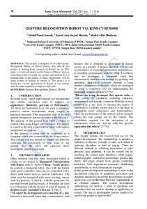
Figure 1.3 Emitted beam pattern of the sonar device
wave (w)
wave (w)
λ w >> δ
α
λ w