OpenVLC: Software-Defined Visible Light Embedded Networks Qing Wang
Domenico Giustiniano
Daniele Puccinelli
IMDEA Networks Institute & University Carlos III of Madrid Madrid, Spain
IMDEA Networks Institute Madrid, Spain
University of Applied Sciences of Southern Switzerland Manno, Switzerland
[email protected]
domenico.giustiniano @imdea.org
ABSTRACT Though there has been a lot of interest in Visible Light Communication (VLC) in recent years, a reference platform based on commercial off-the-shelf components is still missing. We believe that an open-source platform would lower the barriers of entry to VLC research and help the VLC community gain momentum. In this paper we take an initial step toward the goal of a VLC reference platform – OpenVLC, and present our design and implementation. Built around a credit-card-sized embedded Linux platform with an LED front-end, OpenVLC offers a basic physical layer, a set of essential medium access primitives, as well as interaction with Internet protocols. We investigate the performance of OpenVLC and show how it can be used along with standard networking diagnostics tools.
Categories and Subject Descriptors C.2.1 [Computer-Communication Networks]: Network Architecture and Design—Wireless Communication
Keywords Visible light communication, Open platform, Design, Implementation, Evaluation
1.
INTRODUCTION
The rapid proliferation of personal smart devices is driving the creation of innovative services. Mainstream research focuses on leveraging Radio Frequency (RF) communication, but using RF to implement data-intensive services will soon exacerbate the spectrum crunch problem. The adoption of the emerging Visible Light Communication (VLC) as a complementary technology would help significantly in this sense, as the visible light spectrum is much wider than the RF spectrum. The uptake of VLC based on Light Emitting Diodes (LEDs) would also reduce the long-term health hazards caused by overexposure to RF energy, for applications such as wearable computing devices. Permission to make digital or hard copies of all or part of this work for personal or classroom use is granted without fee provided that copies are not made or distributed for profit or commercial advantage and that copies bear this notice and the full citation on the first page. Copyrights for components of this work owned by others than ACM must be honored. Abstracting with credit is permitted. To copy otherwise, or republish, to post on servers or to redistribute to lists, requires prior specific permission and/or a fee. Request permissions from
[email protected]. VLCS’14, September 7, 2014, Maui, Hawaii, USA. Copyright 2014 ACM 978-1-4503-3067-1/14/09 ...$15.00. http://dx.doi.org/10.1145/2643164.2643167.
[email protected]
Though there has been a great deal of interest in VLC in recent years, the lack of an open-source reference platform is hindering the progress of the research community. A general-purpose platform would add momentum to VLC research and would open up new avenues of VLC research and spark the interest of researchers and engineers. One such avenue is the application of VLC to networked embedded devices (Networked VLC), which to date remains an unexplored research area that requires a fundamental redesign of the networking stack. This paper takes an initial step toward Networked VLC and introduces OpenVLC, an open-source software-defined networking platform for fast prototyping that runs on a cost-effective yet powerful credit-card-sized embedded board (with a total unit cost of ≈ $50)1 . This paper presents the design of our OpenVLC platform. We interface the LED front-end to an embedded Linux networking platform and provide and implement the primitives, such as signal sampling, symbol detection, coding/decoding, carrier sensing and communication with the Internet layer of the Linux operation system. Furthermore, we design, implement, and evaluate a simple Medium Access Control (MAC) protocol. Our objective is to provide a functional research platform that can be easily extended and configured. In its present form, OpenVLC simply relies on basic off-the-shelf electronic components and only uses a very basic Physical Layer (PHY), though it can be scaled to use more advanced PHYs. Currently, OpenVLC can achieve a MAC layer date rate of 2.2 kb/s at distances up to 1 m. The rest of this paper is organized as follows. The related work is summarized in Sec. 2, and the system design of OpenVLC as well as a simple MAC protocol are presented in Sec. 3. The performance of OpenVLC is evaluated in Sec. 4 in different scenarios. Conclusions are finally drawn in Sec. 5.
2.
RELATED WORK
Some initial efforts in the embedded systems community have underscored the potential of VLC, such as the investigations on point-to-point communication using smartphones [7, 8, 13], cars [9, 13, 14], and toys [11]. It is also receiving strong attention from the designers of the next generation of cellular networks [12]. VLC’s potential usages, challenges of implementation and commercialization, and market conditions are discussed in [3]. The IEEE has developed the 802.15.7 standard [2] for short-range communication using visible light. This stan1
We have created a website to share the source code and electronic schematic of OpenVLC: http://openVLC.com
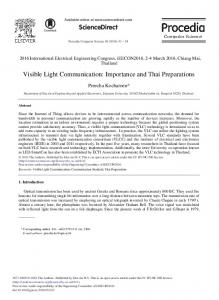
Figure 1: Introducing the VLC communication network. VLC can be a valuable complement to RF communication. dard specifies three PHY layers, which support data rate varying from 11.67 kb/s to 96 Mb/s. It also supports dimming and light flicker prevention. The work in [5] shows an implementation of 802.15.7 protocol using a standard software-defined radio platform from Ettus Research. The implementation cost of the solution is however of at least one magnitude higher than our target platform. In addition, we target the implementation of a platform for networked VLC. While photodiodes are normally used as receivers, in [4] a reverse-biased LED (rather than a photodiode) is used as a receiver to implement a bidirectional LED-to-LED communication. This principle has been exploited by [6] to introduce a LED-to-LED communication network. The authors study fundamental issues of the design of a low-complexity embedded solution, such as efficient collision detection MAC protocol and light flicker elimination. They show that their prototype can achieve a data rate up to 900 b/s and the communication distance is up to 0.9 m. The work is further developed in [10]. Both [6] and [10] operate on microcontrollers and do not support TCP/IP stack and the wide range of networking protocols available in Linux systems. Their design also has the drawback of being sensitive to noise, since it operates with small unamplified currents. None of the above works is intended to be open to the research community.
3.
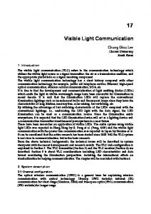
Figure 2: Diagram of the OpenVLC platform. board Cape2 ) allows for quick prototyping of the front-end, and potential extensions of our electronic design.
3.1
• In TX mode, the buffer is enabled and encoded signals are first amplified by the TCA and then fed to the forward-biased LED. • In RX mode, the buffer is disabled to avoid current leakages to the TCA circuitry, and the light signal is received by the reverse-biased LED. The small photocurrent is then amplified by the TIA. Finally, an ADC converts the output analog signals to digital signals, which are then sent to the decoder through the Serial Peripheral Interface (SPI).
OPENVLC
OpenVLC is a general-purpose software-defined platform for networked VLC. It consists of a BeagleBone Black (BBB) board [1], and a front-end transceiver that employs a single LED to both transmit and receive along with a few basic electronic components. Our software solution is implemented as a Linux driver that can communicate directly with the LED front-end and the Linux networking stack. In our design, the VLC interface is set up as a new communication interface that can take advantage of the vast range of Linux tools. Fig. 1 illustrates the motivation of VLC network stack and highlights the layers this paper focuses on. Our platform is built around the BBB, an open-source platform that is cost-effective, easy to use, and powerful. One BBB board only costs $45, but it equips with the TI AM3359 CPU (1GHz), 512MB DDR3 RAM and 2GB onboard flash storage, and provides 4 timers and 65 GeneralPurpose Input/Output (GPIO) pins [1]. The breadboard that can be directly attached to the BBB (BeagleBone Bread-
Bidirectional Communication
OpenVLC’s front-end transceiver reuses the same LED for both transmitting and receiving light signals. An advantage of exploiting the LED for reception rather than adding a photodiode is the lower cost of LEDs compared to photodiodes. Among other benefits, it permits to reduce the design complexity and increase the resilience to ambient (e.g., sunlight) noise without additional signal processing. The block diagram of the transceiver is shown in Fig. 2. It includes a TransConductance Amplifier (TCA) for transmission, a TransImpedance Amplifier (TIA) and an Analogto-Digital Converter (ADC) for reception, a tristate-output buffer, and ancillary circuitry for transmission and reception. A software-defined Transmitter (TX)/Receiver (RX) switch is used to change the LED operation mode between TX and RX through the GPIO pins:
Through the TX/RX switch and the tri-state buffer, OpenVLC can switch the LED between being TX mode and RX mode with low latency. This design offers a basic setup for the objective of this work.
3.2
Software-Defined PHY Layer
The software stack of OpenVLC is illustrated in Fig. 3. Primitives are implemented to build various PHY and MAC layer protocols in the Linux operating system. TX, RX and TX/RX switching. In TX mode, the BBB outputs the signal to be transmitted to the anode of LED for a symbol period of T . In RX mode, the small photo-current is amplified by the TIA and then sampled by 2
http://elinux.org/CircuitCo:BeagleBone_Breadboard
Preamble 3B
SFD 1B
Length 1B
Dst 2B
Figure 4: Frame format: Length= 0 ⇐⇒ACK.
Figure 3: The implementation of the OpenVLC platform in embedded Linux operation system.
the ADC and converted into a digital signal. The BBB samples the output of the ADC at fixed intervals of T . Symbol boundaries are obtained via high-resolution timers of the Linux kernel and handled by our driver. We implement primitives write_to_led(symbol) and read_from_adc() to transmit and receive one symbol, respectively. The LED switches between TX and RX mode through a software-defined controller running on the BBB. The primitives switch_to_tx() and switch_to_rx() allow to switch the LED between TX and RX mode. Modulation and detection. We adopt intensity modulation for data transmission. Binary information is mapped to the presence (symbol HIGH) or absence (symbol LOW) of the visible light carrier. At the transmitter, we use the On-Off Keying (OOK) modulation and the Manchester RunLength Limited (RLL) code. Therefore, bit 1 is mapped to symbol sequence LOW–HIGH, and bit 0 is mapped to HIGH–LOW. At the receiver, demodulation is performed with direct detection. Based on received signal’s voltage, the receiver detects received signal as the sequence of symbols HIGH and LOW that are then converted to binary data. Preamble. The PHY layer transmits each frame with a fixed-length preamble, consisting of an alternate sequence of HIGH and LOW starting with a HIGH symbol. The numbers of HIGH and LOW symbols in the preamble are the same. To convert symbols into binary data, an adaptive symbol detection threshold is adopted. The threshold has to be adaptive because the received light intensity is greatly affected by the free path loss attenuation of light transmitted from the TX to the RX. This detection threshold is obtained on a per-frame basis by averaging out the digital samples of the preamble sequence. The end of the preamble is marked by a Special Frame Delimiter (SFD).
3.3
Software-Defined MAC Layer
The MAC layer generates two types of frames: DATA frames and Acknowledgement (ACK) frames. The frame format is shown in Fig. 4. The frame contains the payload length (Length) of this frame. If the frame has no payload (i.e., Length=0), it is inferred to be an ACK. Otherwise, it is recognized as a DATA frame. The Length field takes
Src 2B
Protocol 2B
Payload 0-255B
CRC 2B
Length> 0 ⇐⇒DATA;
1 byte and each frame carries a payload varying from 0 to 255 bytes. The destination address (Dst) and source address (Src) follow the Length field and each occupies 2 bytes. The 2-byte field Protocol identifies the upper layer protocol encapsulated in the frame payload. Fields from the Length to the Protocol form the MAC header. A two-byte Cyclic Redundancy Check (CRC) over the MAC header and frame payload is appended to the end of each frame. Carrier sensing. Wireless MAC protocols usually employ carrier sensing to reduce collisions. In our VLC platform, we provide two types of carrier sensing: basic sensing and fast sensing. Both are implemented in the PHY layer and can be invoked by the MAC layer. In basic sensing, the platform reads a certain number of continuous symbols. The channel is assessed to be busy if one or more symbols are detected as HIGH symbols; otherwise it is assessed to be clear. Unlike basic sensing, fast sensing operates on persymbol basis. The channel is assessed to be clear if the symbol is detected as LOW, or else it is assessed to be busy. We provide primitives basic_sensing() and fast_sensing() to perform basic and fast sensing, respectively. MAC access protocol. We implement a MAC layer protocol based on the primitives discussed above. We employ a contention-based Carrier Sensing Multiple Access/Collision Detection (CSMA/CD) MAC protocol to ensure fair channel access among all VLC nodes and reduce the impact of collisions [6]. When a frame is available for transmission, the MAC first calls the basic sensing of the PHY layer. The frame is transmitted immediately if the PHY layer reports the channel is clear. If the channel is assessed to be busy, the MAC starts a backoff counter. The counter is initialized with an integer value randomly drawn from a uniform distribution within the range (0, CW-1]. The contention window CW is initialized as CWmin, where CWmin is the smallest size of the contention window. The PHY layer keeps sensing the channel and each time the channel is assessed to be clear, the counter is decremented. The frame is transmitted when the counter reaches zero. Upon frame transmission, the transmitter can engage in fast sensing. This occurs when the transmitter sends a LOW symbol of the Manchester code, as it powers down the LED and is therefore able to switch the LED to RX mode to receive a symbol, as presented in Sec. 3.2. The received symbol is sufficient for fast sensing. Afterwards, the LED is switched back to TX mode to carry on the transmission. The transmitter alternates between TX and RX mode during data transmission. If the transmitter detects a collision, i.e., the channel is assessed to be busy through fast sensing for no less than Bf s times, the ongoing transmission is immediately interrupted. The illustration of the backoff mechanism, basic sensing, and fast sensing in CSMA/CD is shown in Fig. 5. After successfully receiving a frame, the receiver sends an ACK to the transmitter. If the transmitter has not received an ACK within the timeout, it retransmits the frame and doubles the CW (until it reaches a pre-defined CWmax threshold that denotes the maximal size of the contention
Figure 5: Backoff, basic and fast sensing of the CSMA/CD protocol. The transmitter uses OOK with Manchester coding to send data.
PERFORMANCE EVALUATION
As described in Sec. 3, our platform consists of an embedded BBB board and an LED front-end. In the evaluation, the Linux operating system running within the BBB board is the Angstrom Distribution with kernel version 3.8.13. The electronic devices used in the LED front-end are summarized in Table 1. Unless otherwise specified, each node uses a symbol period of T = 200 µs. The MAC layer transmission queue length is set to 100. As presented in Sec. 3, our software solution is a driver that provides a new interface. This interface (vlc0) is shown in Fig. 6, where its various parameter settings are listed with ifconfig Linux command, e.g., MAC and IP addresses, Maximum Transmission Unit (MTU), received and transmitted packets, etc.
4.1
MAC layer
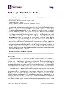
We evaluate the saturation throughput of OpenVLC’s MAC layer under a two-node scenario, where the two nodes are within the Field-Of-View (FOV) of each other. The satura-
Table 1: Electronic devices used in the platform. Model HLMP-EG08-YZ000 74HCT244N 2N3904 LM358N MCP3008
Description Low-power 5 nm red LED with a Field-Of-View (FOV) of 8◦ 8-bit buffer with tri-state outputs Transresistance amplifier Transimpedance operational amplifier 10-bit analog-to-digital converter
2.2 2 1.8 1.6 1.4 1.2
50
100
150
200
Payload (bytes)
MAC throughput (kb/s)
4.
Figure 6: The new interface vlc0 generated from our software solution. We can take advantage of all the networking tools available in Linux.
MAC throughput (kb/s)
window). The frame is dropped when a pre-defined number of retransmissions fail. Interfacing with the Internet layer. We implement the MAC protocol as well as part of the PHY layer as a new driver of the Linux operating system. The MAC protocol will become transparent to various applications if it can connect with the Internet layer. We implement two primitive functions vlc_mac_tx(skb) and vlc_mac_rx(vlc_pkt). The former is called by the Internet layer to move packets to the MAC layer, where are enqueued and wait for transmission scheduling. The latter receives packets from the PHY layer, checks their protocols, and decides whether or not to send them to the Internet layer. By invoking these two functions, any MAC protocols can easily interact with the Internet layer.
2 1.5 1 0.5 0 0.2 0.4 0.6 0.8 1 1.2
Distance (m)
Figure 7: MAC layer throughput under different scenarios. tion throughput is achieved under the setting that one node always has data to transmit to the other node. Throughput versus per-frame payload is shown in the left sub-figure of Fig. 7, where the two nodes are placed at a distance of 0.6 m and the payload varies from 20 to 200 bytes. As expected, the throughput increases as the payload increases, e.g., the saturation throughput is 1.2 kb/s when the payload is 20 bytes; while the throughput achieves 2.2 kb/s after the payload increases to 200 bytes. The achieved saturation throughput versus distance is shown in the right sub-figure of Fig. 7, where the per-frame payload is fixed to 120 bytes. We observe that the communication remains stable if the communication distance is less than 1 m, with an achieved throughput of roughly 2 kb/s. The throughput starts to drop sharply as the distance exceeds 1 m, as the receiver is not able to distinguish between HIGH and LOW symbols any more.
4.2
Application Layer
As we implement the software part of the OpenVLC platform in the Linux operating system and connect it to the upper layers, we can evaluate the OpenVLC’s performance
CPU usage (%)
25 20 15 10 5
VLC off
VLC on
IPT=2s IPT=0.5s
ECDF of the RTT
1 0.8 0.6
CPU usage (%)
(a) Symbol period T = 200 µs
Figure 8: Snapshot of the ping results.
25 20 15 10 5
VLC off
VLC on
IPT=2s IPT=0.5s
(b) Symbol period T = 1000 µs
0.4
IPT=0.5s IPT=0.8s IPT=1s IPT=2s
0.2 0
0
1
2
3
4
5
6
Figure 10: CPU usage under different scenarios.
7
Packet RTT (s) Figure 9: ECDF of the ping packet RTT over a point-to-point link.
using various traditional network measurement tools. In this subsection, we present evaluation results obtained from the well-known network tools ping and iperf under point-topoint link (one-hop) and networking (two-hop) scenarios. In the one-hop scenario, the IP addresses of the two nodes are set to 192.168.0.1 and 192.168.0.2, respectively. In the twohop scenario, a third node with IP address 192.168.0.3 is added and configured as a router to forward packets at IP layer between the other nodes. A ping snapshot is shown in Fig. 8. We observe no packet loss in this single test, and an average Round-Trip Time (RTT) is around 420 ms. The OpenVLC ping performance over various ping Inter-Packet Time (IPT) settings is shown in Fig. 9. These results are collected from 500 ping packets. From the Empirical Cumulative Distribution Function (ECDF) of the RTT in Fig. 9, we observe that when the IPT is set to 2 s, over 95% of all packets incur a RTT below 500 ms. This value drops to 65% when the ping traffic load increases to IPT=0.5 s as a result of the longer queuing time. We also measure the CPU usage under different scenarios, as shown in Fig. 10. The symbol periods are set to 200 µs and 1000 µs in Fig. 10 (a) and (b), respectively. Here the label “VLC off” means the VLC driver is not loaded, while the label “VLC on” indicates the driver is loaded but no traffic is transmitted or received. In addition, “IPT=2s” and “IPT=0.5s” represent the scenarios where one node pings another node and the IPT is set to 2 s and 0.5 s, respectively. From Fig. 10 (a) we first observe that the CPU usage under “VLC off” is about half of that under “VLC on”. Another observation is that the CPU usage keeps at approximately the same level (median of around 18%) after the driver is loaded (irrespective of traffic volume). This is because the driver is
required to continuously listen to the channel even it does not have any traffic to send, and the CPU usage from sending traffic to the channel and listening the channel are almost the same. Furthermore, the CPU usage decreases to a median of around 14% when the symbol period equals 1000 µs and the VLC driver is loaded, as shown in Fig. 10 (b). Finally, we observe a slight impact of pings only for symbol period of 1000 µs. The network testing tool iperf is commonly used to measure throughput. In the following we use this tool to evaluate OpenVLC’s performance. An iperf snapshot for the onehop scenario is shown in Fig. 11. Here the payload of UDP is set to 200 bytes and the result is from the best case of our experiments. We observe that the maximal achievable throughput is 1.76 kb/s and no packet loss is recorded in this single test. Further evaluation results under both the one-hop and two-hop scenarios are shown in Fig. 12. These results are collected by running the experiment shown in Fig. 11 for 15 times under each scenario. From the left subfigure, we can see that the average throughput obtained from iperf in the one-hop scenario is around 1.6 kb/s, while this value is halved in the two-hop scenario. This is because iperf traffic in the two-hop scenario has to traverse two VLC links; since each node is equipped with only one LED,
Figure 11: Snapshot of the throughput evaluation using iperf under one-hop scenario.
Packet loss ratio (%)
Throughput (kb/s)
1.8 1.6 1.4 1.2 1 0.8 0.6
One−hop Two−hop
25 20 15 10 5 0
One−hop Two−hop
Figure 12: Performance evaluation using iperf under one-hop and two-hop scenarios. the router forwarding traffic between nodes can not send and receive simultaneously. The packet loss ratio is shown in the right sub-figure of Fig. 12. We can observe that the average packet loss ratio in the one hop scenario is around 9%. The reason behind this is that currently we have not implemented the matched filtering and timing error recovery, therefore not all the frames can be successfully received and decoded by the receiver. The average packet loss ratio nearly doubles under the twohop scenario, as expected by the fact that each frame has to traverse two hops before arriving at the receiver. The higher number of channel collisions in this configuration further increases the packet loss ratio.
4.3
Discussion
Currently, OpenVLC is designed using basic commercial off-the-shelf components to implement LED-to-LED communication. While being able to be used as a starter kit for VLC research, OpenVLC can be improved by adopting more powerful hardwares and be easily extended to support LED-to-photodiode communication. The matched filtering and timing error recovery, when implemented, can increase the communication range and stability. Our first implementation also reports that the data rate it achieves at the moment is still lower than the lowest data rate specified in the IEEE 802.15.7 standard [2]. The current bottleneck is the speed at which BBB reads symbols from the ADC (comparable to the one of a dedicated microcontroller), which can be greatly improved with continuous sampling available in most recent kernel. We are finding ways to optimize the software part as well as the hardware part of our current implementation.
5.
CONCLUSION
In this paper, we presented the design, implementation, and performance evaluation of OpenVLC – an open source research platform. OpenVLC’s paramount goal is to demystify VLC and lower the barriers of entry to VLC research. Much like the Berkeley motes demystified low-power wireless a decade ago and paved the way to a decade’s worth of rich and active research in wireless sensor networks, we believe that an open reference platform may help VLC to embrace a larger community, especially in the previously unexplored domain of VLC networks for embedded devices. OpenVLC
leverages the recent diffusion of powerful but cost-effective embedded Linux platforms to provide a reference platform that allows the reuse of the vast array of Linux tools. OpenVLC also shows how a handful of commercial off-the-shelf components can suffice as a starter kit for VLC research. Going forward, we hope that OpenVLC can create bridges between VLC and wireless embedded system communities. We envision that research groups in embedded systems with no prior VLC experience can use OpenVLC to explore the realm of visible light, while research groups with a solid VLC background can easily expand OpenVLC and enrich its set of functionalities, for instance with better hardware and more advanced PHY designs.
6.
ACKNOWLEDGMENTS
We thank Marco Zuniga and Lennart Klaver for their constructive discussions and comments.
7.
REFERENCES
[1] BeagleBone Black. http://beagleboard.org/Products/BeagleBone+Black. [2] IEEE standard for local and metropolitan area networks–part 15.7: Short-range wireless optical communication using visible light. IEEE Std 802.15.7-2011, pages 1–309, Sept 2011. [3] H. Burchardt, N. Serafimovski, D. Tsonev, S. Videv, and H. Haas. VLC: Beyond point-to-point communication. IEEE Communications Magazine, 52(7):98–105, July 2014. [4] P. Dietz, W. Yerazunis, and D. Leigh. Very low-cost sensing and communication using bidirectional LEDs. In TR2003-35, 2003. [5] C. Gavrincea, J. Baranda, and P. Henarejos. Rapid prototyping of standard-compliant visible light communications system. IEEE Communications Magazine, 52(7):80–87, July 2014. [6] D. Giustiniano, N. Tippenhauer, and S. Mangold. Low-complexity visible light networking with LED-to-LED communication. In Proceedings of the IFIP Wireless Days (WD), pages 1–8, 2012. [7] T. Hao, R. Zhou, and G. Xing. Cobra: Color barcode streaming for smartphone systems. In Proceedings of the ACM MobiSys, pages 85–98, 2012. [8] W. Hu, H. Gu, and Q. Pu. Lightsync: Unsynchronized visual communication over screen-camera links. In Proceedings of the ACM MobiCom, pages 15–26, 2013. [9] C. B. Liu, B. Sadeghi, and E. W. Knightly. Enabling vehicular visible light communication (V2LC) networks. In Proceedings of the ACM VANET, pages 41–50, 2011. [10] S. Schmid, G. Corbellini, S. Mangold, and T. R. Gross. LED-to-LED visible light communication networks. In Proceedings of the ACM MobiHoc, pages 1–10, 2013. [11] N. Tippenhauer, D. Giustiniano, and S. Mangold. Toys communicating with LEDs: Enabling toy cars interaction. In Proceedings of the IEEE CCNC, pages 48–49, 2012. [12] D. Tsonev, S. Videv, and H. Haas. Light fidelity (Li-Fi): towards all-optical networking. In In Proceedings of SPIE, volume 9007, pages 900702–900702–10, 2013. [13] T. Yamazato, I. Takai, H. Okada, T. Fujii, T. Yendo, S. Arai, M. Andoh, T. Harada, K. Yasutomi, K. Kagawa, and S. Kawahito. Image-sensor-based visible light communication for automotive applications. IEEE Communications Magazine, 52(7):88–97, July 2014. [14] S.-H. Yu, O. Shih, H.-M. Tsai, and R. Roberts. Smart automotive lighting for vehicle safety. IEEE Communications Magazine, 51(12):50–59, 2013.