is based on cross-gain modulation in a semiconductor optical amplifier. We also ... we explain how an optical threshold function (OTF) can be em- ployed for ...
2
JOURNAL OF LIGHTWAVE TECHNOLOGY, VOL. 21, NO. 1, JANUARY 2003
Optical Packet Switching and Buffering by Using All-Optical Signal Processing Methods H. J. S. Dorren, M. T. Hill, Associate Member, IEEE, Y. Liu, Student Member, IEEE, N. Calabretta, A. Srivatsa, F. M. Huijskens, H. de Waardt, and G. D. Khoe, Fellow, IEEE
Abstract—We present a 1 2 all-optical packet switch. All the processing of the header information is carried out in the optical domain. The optical headers are recognized by employing the two-pulse correlation principle in a semiconductor laser amplifier in loop optical mirror (SLALOM) configuration. The processed header information is stored in an optical flip-flop memory that is based on a symmetric configuration of two coupled lasers. The optical flip-flop memory drives a wavelength routing switch that is based on cross-gain modulation in a semiconductor optical amplifier. We also present an alternative optical packet routing concept that can be used for all-optical buffering of data packets. In this case, an optical threshold function that is based on a asymmetric configuration of two coupled lasers is used to drive a wavelength routing switch. Experimental results are presented for both the 1 2 optical packet switch and the optical buffer switch. Index Terms—Optical flip-flop memories, optical header recognizing, optical packet switching, optical signal processing, wavelength conversion.
I. INTRODUCTION
O
PTICAL packet–switched networks are emerging as a serious future candidate in the evolution of optical telecommunication networks. During recent years, a number of strategies toward optically packet-switched networks have been developed, in particular [1]–[4]. All of these approaches have in common that they are hybrid electrooptical packet-switching methods; the optical packet header is processed electronically, while the packet payload remains in the optical domain. In this paper, we review results that were published by us in [5]–[13] in order to discuss optical packet-switching and buffering technology, in which all the necessary header-processing steps are carried out in the optical domain. We focus on optical packet-switched cross connects that have a generic node structure as schematically presented in Fig. 1. A hybrid electrooptical packet-switching concept that assumed such a node structure was presented in [4]. It follows from Fig. 1 that in the switching fabric, three important steps take place: synchronization of the packets, buffering of the packets, and
Manuscript received November 27, 2001; revised May 28, 2002. This work was supported by the Netherlands Organization for Scientific Research (NWO) through the “NRC photonics” grant. H. J. S. Dorren, M. T. Hill, Y. Liu, N. Calabretta, F. M. Huijskens, H. de Waardt, and G. D. Khoe are with the COBRA Research Institute, Eindhoven University of Technology, 5600 MB, Eindhoven, The Netherlands. A. Srivatsa is with the COBRA Research Institute, Eindhoven University of Technology, 5600 MB Eindhoven, The Netherlands, on leave from the Optical Communications Research Laboratory, Stanford University, Stanford, CA 94305 USA. Digital Object Identifier 10.1109/JLT.2002.803062
switching of the packets. In [4], it was shown that electronically controlled wavelength routing switches could carry out all of these operations. In this paper, we first present an all-optical packet-switch concept that can be employed for optical packet-switching and optical synchronization purposes. Later, we explain how an optical threshold function (OTF) can be employed for all-optical buffering purposes. In order to realize all-optical packet switching, approaches must be developed to optically process the header information. We believe that two functions have to be developed in optics in order to realize all-optical packet switching. The first function is an all-optical header recognizer, and the other function is an all-optical flip-flop memory that is required to store the header information for the duration of the packet. There are a number of methods published for all-optical processing of the header information. In [14], an all-optical method for processing packet headers is presented that uses tuneable fiber Bragg gratings (FBGs). Ultrafast all-optical header recognition has been reported in [3], [15] by using four-wave mixing (FWM) in a semiconductor optical amplifier (SOA) and in [16] by using terahertz optical asymmetric demultiplexers (TOADs). Both methods require a form of optical clock recovery that introduces additional complexity in the switching system. In this paper, we discuss a header-processing method that is based on the two-pulse correlation principles in a semiconductor laser amplifier in loop optical mirror (SLALOM) configuration [5]. The advantage of this method is that it is does not require optical clock recovery, which reduces the complexity of the header recognition system. Moreover, the method can be used to recognize low-power optical headers. On the other hand, header recognition by using two-pulse correlation in a SLALOM structure only works for well-chosen header patterns. Moreover, Manchester encoding of the payload is necessary to guarantee that the header pattern is not repeated in the packet’s payload. In [6], how a multiple-output low-power optical header processor could be realized is discussed. The second function that we discuss in order to realize all-optical switching of data packets is an all-optical flip-flop memory function. In [17] a review is presented on available technology with respect to optical flip-flop memories. We use in our optical packet switch an all-optical flip-flop concept that is based on the bi-stable operation of two coupled laser diodes. The operation principle of the optical flip-flop is described in [7] and [8]. The optical flip-flop that we use in this paper has a number of advantages. First, it can provide high contrast ratios between the states. Moreover, there is no different mechanism for the set and reset operation. Furthermore, the wavelength range of
0733-8724/03$17.00 © 2003 IEEE
DORREN et al.: OPTICAL PACKET SWITCHING AND BUFFERING BY USING ALL-OPTICAL SIGNAL-PROCESSING METHODS
Fig. 1.
Generic node structure for all-optical packet-switched cross connects.
Fig. 2.
System concept for 1
3
2 2 all-optical packet switch.
the input light and the output wavelength can be large, and the flip-flop has controllable and predictable switching thresholds. Finally, the flip-flop operation does not rely on second-order laser effects and is not tied to a specific structure or technology. We demonstrate in this paper a 1 2 all-optical packet switch concept that uses a SLALOM structure as a header processor and an optical flip-flop memory based on coupled laser diodes to store the processed header information. The packet switch concept that we present is bit-rate transparent for both the header and the payload, and the technology used allows photonic integration. 2 optical packet presented in this paper is based The 1 on wavelength routing principles and can therefore only handle one packet at any given moment. If two packets arrive at the same time at the same packet switch, optical buffering has to be applied to avoid packet contention. In [4] and [18]–[20], hybrid electrooptical buffering concepts are explained and demonstrated. Performance analyses of optical buffers are presented in [21] and [22]. In [23], an all-optical buffering concept is demonstrated that allows a variable optical delay. The optical packet switch that we present can also be used for all-optical buffering. However, all-optical buffering requires less functionality than optical packet switching, since all-optical buffering of data packets does not require header recognition. Later in this paper, it is demonstrated that using an optical threshold function that controls a wavelength routing switch is sufficient to route optical packets into a fiber buffer. The paper is organized as follows. In Section II, the all-optical switch concept is explained. We first explain the operation principle of the optical packet switch. Later, we focus on describing the optical header-processing method and the optical flip-flop memory in detail. Experimental results that demonstrate the operation of the packet switch are given. In Section III, we describe the operation of the optical buffering concept that we have de-
veloped. Experimental results are given. In Section IV, the paper is concluded with a discussion. II.
ALL-OPTICAL
1
2 PACKET SWITCH
A. Operation Principle The concept of our optical switch based on all-optical signal processing is presented schematically in Fig. 2. The all-optical packet switch is composed of three functional blocks: the all-optical header-processing block, the all-optical flip-flop memory block, and the wavelength conversion block. The packets that we use have a fixed duration and consist of an optical header and optical payload. Between the header and the payload, there is some guard time. The header contains the routing information of the packet while the payload contains the information content. Both the header and the payload consist of amplitude-modulated data bits. When an optical packet arrives at the optical packet switch, the optical power of the packet is split into two parts. Half of the optical power of the packet is delayed and injected into a wavelength converter. Some delay is required to compensate for the time taken to carry out the header-processing functions. The principle that is used for wavelength conversion is cross-gain modulation (XGM) [24]. Wavelength conversion by using XGM can be obtained in an SOA by simultaneously injecting a continuous-wave (CW) signal and a modulated data signal into the SOA. The CW signal must have a different wavelength than the data signal. The modulation of the carriers ensures that the data signal is copied onto the CW signal. By using a demultiplexer, the desired wavelength channels can be separated spatially. Wavelength conversion by using XGM leads to an inverted data signal. By using a combination of XGM and cross-phase modulation through interferometric wavelength converters, a noninverted signal can be obtained
4
JOURNAL OF LIGHTWAVE TECHNOLOGY, VOL. 21, NO. 1, JANUARY 2003
Fig. 3. Experimental setup to demonstrate SLALOM-based serial all-optical header processor. Traffic from the network is coupled into the HPU at port 1, and the processed output appears at port 2.
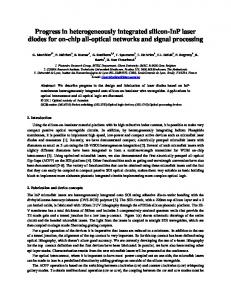
[24]. At the output of the packet switch, the wavelengths of the routed packets could be set back to the original wavelength by using integrated wavelength converters (not shown in Fig. 2). In order to use wavelength conversion principles to route optical packets all-optically, the binary optical header pattern must be translated into a CW signal of the desired wavelength. To obtain this goal, we first have to recognize the header bits. Section II-B describes how the two-pulse correlation principles in a SLALOM structure can be used for recognizing optical headers all-optically. It is shown that for uniquely chosen header patterns, a correlation pulse at the output of the header processor is formed. The correlation pulse at the output of the header processor is converted into the CW that is necessary to obtain the wavelength conversion by an optical flip-flop memory, which is described in Section II-C. The operation of the optical flip-flop memory is based on the bi-stable operation of a system of two coupled laser diodes. The optical flip-flop memory’s output is fed into the wavelength converter to convert the packet into the desired wavelength. We proceed in this section by describing the operation principles of the optical header processor and the optical flip-flop memory in detail. In Section II-D, an experiment is described in which optical packet switching is demonstrated. B. All-Optical Header Processing The first function block that we will discuss is that of the optical header-processing function (see Fig. 2). We employ the two-pulse correlation principle of an SOA in a SLALOM configuration to recognize optical packet headers all-optically [5], [6]. The header-processing unit (HPU) is implemented using the structure shown in Fig. 3. A sample packet structure is shown in the upper panel of Fig. 4. The optical header consists of a hexadecimal FF0FF pattern followed by a guard band consisting of a hexadecimal 000 pattern. The optical payload consists of 80 B of a pseudorandomly generated Manchester-encoded data stream. Finally, the packet has a tail section consisting of a hexadecimal FFFFFF pattern. The header and tail sections are effectively at a lower bit rate than the payload. If a packet as described previously enters the HPU at port 1, the two-pulse correlation principle in a SLALOM configuration can be employed for processing the optical header. To obtain
Fig. 4. Packet structure for the HPU is shown. The header and tail bits are at the slower bit rate of 2.5 Gb/s. The output from the packet is shown in the lower panel. The header and tail pulses are large in amplitude and wide in duration. The packet payload is suppressed by 14.95 dB. The time scale is 10 ns/div, and the voltage scale is 10 mV/div.
two-pulse correlation in a SLALOM configuration, three time scales play an important role. First, there is the time between the two pulses. Moreover, there is the time that represents the displacement of the SOA with respect to the center of the loop. The third time scale is the recovery time of the SOA. If we choose and larger than , we can distinguish three impor. This implies that tant cases. The first case is when the first pulse of the counterclockwise propagating pulse arrives at the SOA between the two pulses of the clockwise propagating signal. As a result of this, all the pulses in the packet header receive full gain, and no correlation pulse is formed at the output . This is the case port. The second case is when in which a correlation pulse is formed, since the first pulse of the counterclockwise propagating pulse experiences a saturated SOA due to the second pulse of the clockwise propagating signal . This implies that the [25]. The third case is when first pulse of the counterclockwise propagating signal arrives at the SOA after the second pulse of the clockwise propagating signal has left the SOA. Hence, all the involved pulses receive full gain, and no correlation pulse is formed at the output port. Suppose that a packet with a hexadecimal FF0FF header encorresponds ters the HPU. Here, we assume that the time to the time represented by the hexadecimal symbol 0 between the header pulses. The header pulses are both represented by
DORREN et al.: OPTICAL PACKET SWITCHING AND BUFFERING BY USING ALL-OPTICAL SIGNAL-PROCESSING METHODS
5
Fig. 5. Arrangement of two coupled identical lasing cavities, showing the possible states. In state 1, light from laser 1 suppresses lasing in laser 2. In state 2, light from laser 2 suppresses lasing in laser 1. To change states, lasing in the master is halted by injecting light with a different wavelength.
the hexadecimal symbol FF. The delay time is chosen so that , and thus, a correlation pulse is formed at the output of the header processor. However, if a packet with a F000F enters the HPU, no correlation pulse is formed, since the time between the two pulses is so large that the first pulse of the counterclockwise propagating signal arrives at the SOA after the second pulse of the clockwise signal. Hence, both pulses receive full gain, and no correlation pulse is formed. The high bit rate optical payload is suppressed because it drives the SOA in saturation. In order to obtain efficient suppression of the payload, a tail section is necessary to guarantee that the SOA remains in saturation when the payload passes through. A tail section is useful in applications where the packet size is variable, and packet length information is needed. Manchester encoding of the packet payload is used to achieve a crucial criterion of the header processor—the need to differentiate between header and payload. By Manchester encoding the payload, it is ensured that the header sequence will never be duplicated in the payload. Therefore, the payload will never be able to produce the correlation pulses made by header data streams. In addition, the Manchester encoding increases the suppression of the payload by keeping the SOA in saturation when the payload passes through. The saturated SOA can only provide a limited gain to the payload. The tail section is included to ensure that the SOA stays saturated for the entire payload. The disadvantage of Manchester encoding is the loss of effective bit rate in the payload; however, this is offset by such benefits as easier clock recovery in packet-switched applications. Experimental evidence to demonstrate the operation of the header processor is given in the lower panel of Fig. 4. A 10-Gb/s Mach–Zehnder modulator was used to create the packet structure. The displacement of the SOA with respect to the loop is equal to 4.95 ns (this corresponds to 1 m of fiber). The clock frequency of the modulator was 9.5152 GHz to match with the displacement of the SOA. The SOA was pumped with 130 mA of current. The averaged input power of the packets was 5 dBm. In Fig. 4, the SLALOM’s output is shown. The correlation pulse, the suppressed payload, and the tail sections are clearly visible. This result clearly indicates that a SLALOM structure can be used to recognize optical packet headers, since only header
patterns that match with the SLALOM design produce a correlation pulse at the HPU’s output. Moreover, it is only the time between the two pulses that plays a role in the header recognition. This implies that the same SLALOM configuration can be used to recognize optical headers at a different bit rate. The setup, as presented in Fig. 3, can be used to recognize an optical header at a data rate of 622 Mb/s, but two-pulse correlation can also be successfully demonstrated at 10-Gb/s header data rates. The fact that the SLALOM structure is capable of recognizing optical packets at different bit rates means that the packet switch, as we describe it later in this paper, is also capable of operating at different header bit rates and payload bit rates. Finally, the contrast between the correlation pulse and the suppressed payload increases if the bit rate increases. This is due to the gain saturation of the SOA. If a data bit passes through, the SOA gain rapidly saturates. Afterwards, the SOA gain slowly recovers. The recovery time of the SOA gain is in the order of a nanosecond. For a low data rate (2.5 Gb/s), the bit time is about 0.4 ns. In this time, the SOA gain typically recovers by about 50%. If the data rate is higher, the time between two bits is shorter, and thus, there is less recovery of the SOA gain. In the case of high-bit-rate optical data, the clockwise and counterclockwise signals makes the SOA remain in deep saturation, and the entire optical payload is suppressed. Theoretical analysis predicts approximately 18-dB suppression for packet payload at a data rate of 40 Gb/s.
C. All-Optical Flip-Flop Memory The all-optical flip-flop memory that we use is based on two coupled lasers with separate laser cavities. The device is depicted in Fig. 5. The system can have two states. In state 1, light from laser 1 suppresses lasing in laser 2. In this state, the optical flip-flop memory emits CW light at wavelength . Conversely, in state 2, light from laser 2, suppresses lasing in laser 1. In state 2, the optical flip-flop memory emits CW light at wavelength . To change states, lasing in the dominant laser can be stopped by injecting external light with a different wavelength. The output pulse of the optical header processor is used to set the optical flip-flop memory into the desired wavelength.
6
JOURNAL OF LIGHTWAVE TECHNOLOGY, VOL. 21, NO. 1, JANUARY 2003
Fig. 6. Output power of the two coupled lasers versus increasing external light injected into laser 1. The solid curve represents the output power of laser 1 (1549.32 nm). The dotted curve represents the output of laser 2 (1552.52 nm). It is clearly visible that laser 1 switches OFF and laser 2 switches ON. The external injected light is at the wavelength � (1560.61 nm).
In [8], it is shown that the optical flip-flop memory can be described by four coupled differential (rate) equations, representing the carrier densities and photon densities of each laser, respectively. We first assume that the lasers are identical so that the arrangement of coupled lasers is symmetric. With respect to the operation of the all-optical packet switch, two important results are presented in [8]. The first result is shown in Fig. 6 and concerns the switching power of a symmetric system of two coupled lasers. On the horizontal axis, the increasing optical power of external light that is injected into laser 1 is plotted. The vertical axis represents the output power of laser 1 and laser 2. It is clearly visible that if the amount of external light that is injected into laser 1 exceeds a critical threshold level (here approximately 0 dBm), laser 1 switches OFF, and laser 2 switches that is required to change states is ON. The amount of light P given by [8]
(1) represents the reflectivity at the end facets of each In (1), laser, and is the coupling between the two laser cavities and the photon energy. Furthermore, v is the group velocity, and is the length of the active region in the laser. Finally, is the is the injection current, is the electronic charge unit, and carrier lifetime. The threshold carrier number N is given by (2) In (2), is the volume of the active region in the laser cavity, is a confinement factor, is the gain factor, and N is the carrier number at transparency. Finally, the photon lifetime is defined by (3) represents the internal losses in the laser cavity. From where (1)–(3), the switching power can be computed. Changing the changes the laser laser current and the facet reflectivity output power and also the flip-flop switching power. However, P can be varied independently from the laser output power by changing . The fact that the optical flip-flop memory can change states with low switching power is important for the design of the optical packet switch. It makes it possible to bias the
Fig. 7. Ring-laser implementation of the optical flip-flop memory.
optical flip-flop in such a way that it can be set or reset by the optical header processor output. The flip-flop can distinguish between the difference in optical power of the correlation pulse and the suppressed payload by biasing the laser currents in such a way that P is exceeded by the correlation pulse but not by the suppressed payload. In [8], the stability for coupled laser systems is discussed. The underlying concept for the operation of the optical flip-flop memory is suppression of the lasing modes by injection of external light. In principle, we can have two different cases of stability. In the first case, the coupling between the two lasing cavities is weak. By this, we mean that the maximum amount of light that is coupled from laser 1 into laser 2 and from laser 2 into laser 1 is insufficient to suppress lasing. Hence, for a sufficient injection current , both the lasers are above threshold and lasing with the identical power. In the second case, the coupling between the two lasing cavities is so strong that the amount of light that is coupled from laser 2 into laser 1 or from laser 1 into laser 2 is sufficient to suppress lasing. In this case, lasing in one of the lasers is suppressed, and only one of the coupled lasers is lasing. The system is now either in state 1 if laser 1 is lasing or in state 2 when laser 2 is lasing. Switching of the states can be established if an amount of light is injected into the dominant laser that exceeds the switching power given in (1). If the system of two coupled laser diodes is biased asymmetrically, the system can form an all-optical threshold function. The system of two coupled lasers can be made asymmetric by setting the bias current differently for laser 1 as for laser 2. As a result of this, laser 1 injects a different amount of light into laser 2 than the amount of light that laser 2 injects into laser 1. We assume that the amount of light that laser 1 injects into laser 2 is sufficient to suppress lasing of laser 2. Hence, laser 1 is the dominant laser. On the other hand, we assume the amount of light that laser 2 injects into laser 1 is not sufficient to suppress lasing of laser 1. If we however, inject an additional amount of external light into laser 1 so that the combined power injected into laser 1 exceeds the power required to suppress lasing, laser 1 can be temporarily switched OFF. Hence, laser 2 becomes the dominant laser as long as the external light is injected into laser 1. As soon as injection of external light stops, the system switches back and hence, laser 1 becomes the dominant laser again. The system of two coupled lasers is now an OTF instead of an optical flip-flop memory. In Fig. 7, the experimental setup for an experiment to demonstrate the optical flip-flop memory and the OTFs is presented. The two SOAs act as the lasers gain media. In this particular
DORREN et al.: OPTICAL PACKET SWITCHING AND BUFFERING BY USING ALL-OPTICAL SIGNAL-PROCESSING METHODS
Fig. 8. Spectral output of two states of the optical flip-flop memory is presented. The solid curve represents the state in which laser 1 is lasing, and the dotted curve represents the state in which laser 2 is lasing.
Fig. 9. Oscilloscope traces showing power of laser 1 and laser 2. The regular toggling between the states can be clearly seen.
setup, a ring-laser configuration is used. We have chosen for Fabry–Pérot filters with a bandwidth of 0.18 nm as wavelength selective elements. The SOA 1 was pumped with 168 mA of current SOA 2 was pumped with a 190 mA of current. The pulses that were used to set and reset the flip-flop had a power of 2 mW. The optical spectrum of the flip-flops’ output states is presented in Fig. 8. It is clearly visible that the difference in output power between the two states is more than 45 dB. The switching characteristics of the optical flip-flop are presented in Fig. 9. It can be observed from Fig. 9 that if sufficient external pulse is coupled in the flip-flop, the system changes states. From these experiments, we can conclude that a system of two coupled laser diodes can form an optical flip-flop memory. The state of the optical flip-flop can be controlled by injecting external light not of lasing wavelength. Equation (1) gives the amount of power that has to be injected in the system to change states. It follows from (1) that changing the driving current and coupling can change the amount of external light that has to be injected in the optical flip-flop to change states. Finally, when the system of two coupled lasers is biased asymmetrically, the system can form an OTF. D. All-Optical Packet Switch Experiment The experimental setup for demonstration of an all-optical packet switch experiment is presented schematically in Fig. 10. The setup that is presented in Fig. 10 employs all the functionality that is described in Fig. 2. It contains an optical header processor based on the two-pulse correlation principle in a SLALOM configuration, an optical flip-flop memory based on two coupled lasers, and a wavelength routing switch based on XGM. In the particular experiment, the data rate of the packet payload was 2.5 Gb/s. The header pattern was repeated for a duration of 7.5 s. The payload consists of a data stream of
7
35 s of Manchester-encoded pseudorandomly generated bits. Header and payload were separated by 5 s of guard time. The time between the packets was 17.5 s. We distinguish between packets with two kinds of headers. The first packet header (Header 1) consists of a repeated hexadecimal FF0FF00 pattern. The second packet header (Header 2) consists of a repeated hexadecimal 0 000 000 pattern. Packets with alternating headers were used throughout the experiments. The optical power of an optical packet arriving at the packet switch is split in two equal parts. Half of the optical power of the packet is delayed by 2.8-km fiber and injected into a wavelength converter. The other half of the optical power is fed into the header processor. Suppose a packet with Header 1 enters the SLALOM that is employed for header processing. Section II-B discusses that the two-pulse correlation principle of SLALOM causes a correlation pulse to appear at the SLALOM’s output. The high–bit-rate payload is suppressed because the SOA is driven into saturation [5], [6]. The SOA current in the SLALOM was 136 mA, and the averaged input power of the data packets was 3 dBm. The SLALOM’s output is then passed through an OTF to differentiate more strongly between the correlation pulse and the suppressed payload. The SOAs in the OTF were pumped with 135.6 mA and 198 mA, respectively. The threshold function increases the contrast between the correlation pulse and the suppressed payload from 3 dB at the output of the SLALOM to over 25 dB. The output of the threshold function is then amplified by an EDFA and filtered. If a packet with Header 2 enters the SLALOM structure, then no correlation pulse is formed, and consequently, no pulse is generated by the optical header processor [5], [6]. The output of the header processor produces an optical pulse when there is a packet containing Header 1, indicating that the packet should be routed to wavelength . The optical power of the pulse is split into two parts. One half of the pulse is sent directly to the set input of the optical flip-flop. This pulse sets the output wavelength of the flip-flop to wavelength . The other half is delayed by the 12.5-km fiber and resets the , after a delay equal flip-flop output back to wavelength to the packet length. The SOAs in the flip-flop were pumped with 250 mA and 220.9 mA of current, respectively. The optical flip-flop memory implemented here employed coupled ring lasers using Fabry–Pérot filters as wavelength selective and , respecelements, corresponding to the wavelength tively. This implementation provided a low-noise light source suitable for wavelength conversion. The threshold function was implemented using two coupled lasers made from SOAs and fiber Bragg gratings as wavelength selective elements. Finally, the flip-flop output was then fed into a SOA, where the packets were converted to the flip-flop output wavelength via XGM [9]. The SOA that was used for wavelength conversion was pumped with 386 mA of current. The output of the wavelength converter SOA was then passed through a phased-array demultiplexer to spatially separate the two output wavelengths. All the couplers used in the experiment were 50/50 couplers, except those couplers used in the flip-flop. Their coupling ratios are given in Fig. 10. The wavelength outputs 1 and 2 were converted to electrical signals via photodiodes and observed on an oscilloscope.
8
JOURNAL OF LIGHTWAVE TECHNOLOGY, VOL. 21, NO. 1, JANUARY 2003
2
Fig. 10. Experimental setup to demonstrate the 1 2 all-optical packet switch. Traffic from the network is coupled in the packet switch at the input. The packet format is given. SOA: semiconductor optical amplifier. FBG: fiber Bragg grating. EDFA: erbium-doped fiber amplifier. ISO: isolator. PHASAR: phased array demultiplexer.
Fig. 12. Eye diagram of the converted output data when the flip-flop was set to � . The time scale is 100 ps/div, and the voltage scale is 50 mV/div.
III. ALL-OPTICAL BUFFERING Fig. 11. Oscilloscope traces of the optical power at the two switch outputs. Packets with alternating header patterns are fed into the packet switch input. The two different packets are directed to outputs at wavelength � and � . If a packet with a specific header arrives at the packet switch, the designated output wavelength is switched on, and the packet information is modulated on that specific wavelength.
We alternatively sent packets with Header 1 and Header 2 through the packet switch. The resulting waveforms are shown in Fig. 11. The switching of packets between the two wavelengths can be clearly observed. Also shown in Fig. 12 is an eye diagram of the converted output data when the flip-flop was set to wavelength .
A. Operation Principle The all-optical 1 2 packet switch that is presented in the previous chapter is based on wavelength routing principles and can only process one packet at a time, arriving at its input in a cross connect, as presented in Fig. 1. In general, more than one packet can arrive simultaneously at the packet switch. Therefore, optical buffering techniques have to be applied to avoid packet contention. A number of approaches have been discussed and realized [18]–[23]. We present in this paper an all-optical switching concept that is suitable for buffering of data packets. The approach that is
DORREN et al.: OPTICAL PACKET SWITCHING AND BUFFERING BY USING ALL-OPTICAL SIGNAL-PROCESSING METHODS
9
Fig. 13. System concept for all-optical buffering. The OTF acts as an arbiter to decide whether packet contention takes place and drives a wavelength routing switch.
presented schematically in Fig. 13 contains an OTF (see Section II-C) that is used to control a wavelength routing switch [12], [13]. The role of the OTF differs from the role of the OTF in the 1 2 optical packet switch. In the 1 2 optical packet switch, the OTF was used to enlarge the contrast between the correlation pulse and the suppressed payload, whereas in the context of optical buffering, the OTF was used as an arbiter to decide whether packet contention takes place. A system concept for all-optical buffering can be much simpler than a system concept for all-optical packet switching since in the case of all-optical buffering, a packet need only be routed in the buffer for the case of a potential contention. This means that the presence of another packet is used to set the switch and not the information in the packet header. We assume that both packets arrive synchronized at the optical buffer and that packet 1 has a higher priority than packet 2 (see Fig. 13). The wavelength of the packets is . The optical power of packet 1 is first split into two parts: the first part can pass the node directly and is not delayed; another part is injected into the OTF. The OTF is described in Section II-C and acts as an all-optical arbiter to decide whether packet contention takes place. Only if packet contention takes place, packet 2 is routed into a fiber delay line and leaves the optical fiber buffer after packet 1. Crucial in the operation of the OTF (see Section II-C) for buffering data packets is that it takes approximately 20 round-trip times of photons in the laser cavity to make the OTF change states. This means that if the modulation frequency of the packet that is injected is sufficiently high compared with the maximum switching frequency of the OTF, the OTF cannot respond to fluctuations of the optical signal power in the data packet. The OTF responds to the averaged injected signal power. This means that only if an optical packet is injected into the OTF, the output state of the OTF changes. The optical buffering concept that is schematically described in Fig. 13 could have three different nontrivial input cases. In the first case, two packets (say, packet 1 and packet 2) arrive simultaneously at the optical buffer. Due to the presence of packet 1, the OTF is forced into state 2 and emits CW light at wavelength . Hence, the wavelength of packet 2 is converted to and routed into the fiber buffer. Since packet 1 can pass the node directly, the packet contention is resolved. In the second case, only packet 1 is present, while packet 2 is absent. This means that there is no packet contention. Packet 1 can pass the node directly. Part of the power of packet 1, however, is fed into the
Fig. 14. Experimental setup to demonstrate all-optical buffering. MOD: external modulator. EDFA: erbium-doped fiber amplifier. BPF: bandpass filter. ISO: isolator. FPF: Fabry–Pérot filter. Demux: for demultiplexer.
OTF. This makes the OTF switch into state 2, emitting CW light at wavelength . In the third case, packet 1 is absent, while packet 2 is present. In this case, the OTF outputs CW light at due to the absence of packet 1. Thus, the packet wavelength 2 is directed into the pass-port after wavelength conversion. The by using intewavelength of the packets could be reset to grated wavelength converters. B. Optical Buffering Experiment The experimental setup for demonstration of all-optical buffering by using an OTF that controls a wavelength routing switch is presented schematically in Fig. 14. An external modulator is used to generate optical packets at a bit rate of 2.5 Gb/s. The bit patterns in the packets have a nonreturn-to-zero (NRZ) data format and form a pseudorandom binary sequence (PRBS). The packets are then amplified by an erbium-doped fiber amplifier (EDFA) and subsequently filtered by a tunable bandpass filter with 3-nm bandwidth. An optical splitter is used to direct half of the optical power of the packet into the OTF via an optical circulator. This represents packet 1 (see Fig. 13). The other half of the optical power is coupled into a 90/10 coupler. The input averaged input power of the packets is 3 dBm. A part goes directly to the output, representing the part of packet 1 that passes the node directly (see Fig. 13). The Fabry–Pérot filters used in the optical threshold function were 1549.32 nm and 1552.52 nm (see chosen so that Fig. 14). The SOA currents were 177 mA (threshold current is 82 mA) for laser 1 and 192 mA (threshold current is 117 mA) for laser 2. The second part is first delayed by 1.95 s (390 m of fiber), corresponding to the time that is needed to let the OTF change states and then fed into the wavelength converter. This represents packet 2 in Fig. 13. By splitting the optical power of a packet in two parts, we simulate the situation in which two packets arrive at the same time at the optical buffer. The wavelength of the packet is converted via XGM. The
10
JOURNAL OF LIGHTWAVE TECHNOLOGY, VOL. 21, NO. 1, JANUARY 2003
Fig. 15. Oscilloscope trace after wavelength conversion, showing that the packet is error-free converted to wavelength � .
Fig. 16. Oscilloscope traces for 2.5-Gb/s packets, demonstrating the all-optical buffering.
wavelength converter was pumped with 350 mA of current. The demultiplexer spatially directs the packet into a different port based on the wavelength of the packet. In the buffer-port, 9.95 km of fiber corresponding to a delay of 49.75 s is used for buffering purposes. In the experiment we demonstrate that an OTF in combination with a wavelength routing switch can be used for buffering purposes. An optical packet, representing Packet 1, is injected into the OTF and changes the state of OTF into State 2 (laser 2 dominant). Thus, the dominant wavelength of the OTF is . Meanwhile, another packet, representing packet 2 (see Fig. 13) is coupled into the wavelength converter and its wavelength is converted to via XGM. The result is shown in Fig. 15, which for the duration of wavedepicts the packet converted into length . The optical power of the packet is relatively small due to gain saturation in the wavelength conversion. The eye pattern of converted pulses in the packet after the wavelength conversion is also presented in Fig. 15. In Fig. 16, the result of the all-optical buffering is presented. Fig. 16(a) shows the oscilloscope traces of the packets that pass the node directly with the wavelength . Fig. 16(b) shows the oscilloscope traces of the packets that are directed into the buffer port and experience a 49.75- s delay that is caused by a 9.95-km fiber delay line. These packets represent packet 2 (see Fig. 13). The averaged output power of packet 2 is 5 dBm. Fig. 16 clearly shows that the all-optical buffering functions correctly when two packets contend for the output port. IV. CONCLUSION The advantage of all-optical switching technology over hybrid electrooptical packet-switch technology is that the all-optical approach allows a much higher processing speed than the hybrid electrooptical approach. In our experiment, the packet
payload data rate was 2.5 Gb/s. This was limited by the wavelength converter and could potentially reach 100 Gb/s [26]. The header data rate, however, was much slower. This was due to the particular implementation of the optical threshold function and flip-flop used in the experiment. The lasers used to form these functions were constructed from standard commercially available fiber pigtailed components having cavity lengths of many meters. Thus, the component lasers had low intrinsic modulation bandwidths, which limited the speed of the threshold function and the flip-flop. However, integrated versions of these functions using lasers with cavity lengths of less than a millimeter could attain speeds in the GHz range, allowing high header data rates and shorter packet lengths. Moreover, by using optical flip-flops that are not based on coupled laser operation, but on, for instance, coupled Mach–Zehnder interferometers, ultrafast operation of all-optical flip-flops is possible [11], [12]. The laser-based optical flip-flop, however, provides a high ON-OFF contrast ratio. This makes a laser-based all-optical flip-flop ideal to control a wavelength routing switch with low crosstalk. The optical header-recognizing concept that is explained in this paper is bit-rate transparent. By this, we mean that the same SLALOM can be used to recognize optical headers at a different bit rate. Since the operation of the optical flip-flop only depends on the presence of a correlation pulse, this implies that the optical header-processing concept as we present in this paper is bit-rate transparent for the header bit rate. The routing of the optical payload is based on a wavelength conversion principle that is also bit-rate transparent. The header-processing method as we present it can be extended to recognize a large number of header patterns. In [5], it is shown that the SLALOM-based header recognizer could also be used to recognize more complete header patterns. In [6], it is shown how this could be used in a packet-switching context. As a result of this, the optical packet switch can also be generalized all-optical packet switch. The packet-switching conto a 1 cept that we have presented in this paper requires only a limited amount of active components. Moreover, the packet switch does not require optical clock recovery. Finally, the packet switch allows photonic integration. We have also presented an approach to all-optical buffering in which an OTF is used to control a wavelength routing switch. This method is advantageous, since we need no complicated header recognition techniques to route an optical packet into a fiber buffer. Crucial in our method is the OTF that controls a wavelength converter switch. Experimental results indicate that a contrast ratio of more than 45 dB between the output states in OTF can be obtained. Moreover, error-free propagation through the wavelength converter can be obtained. It is beyond the scope of this paper to discuss switching architectures in which all-optical buffers are implemented. Results for electrooptical packet-switched cross connects can be found in [4]. The optical buffer that we present in this paper is capable of handling packet contention of two optical data packets that arrive simultaneously at the packet switch. The OTF that decides whether packet contention takes place can be generalized into a laser neural network (LNN), as published in [27]. The LNN can act as a flexible optical logic gate that can be used to develop an all-optical buffer with more inputs. An example in which three packets arrive simultaneously at the packet buffer is discussed
DORREN et al.: OPTICAL PACKET SWITCHING AND BUFFERING BY USING ALL-OPTICAL SIGNAL-PROCESSING METHODS
in [28], but in principle, the concept can be extended further. It should be noted, however, that the switching speed of the LNN reduces if more inputs are applied [27]. We want to conclude by making some remarks on the stability of the OTF. It can be witnessed from Fig. 6 that in the case of an optical flip-flop memory made out of two coupled lasers, a sharp transition between the two states takes place around a switching power of 1 mW. If the system is operated as an OTF, the transition is less sharp, as in Fig. 6, but it turns out that there is still a contrast of 37 dB over a range of 0.47 mW. Given the , fact that the injected current controls the switching power this result implies that the OTF performs a stable operation, as long as an averaged power of the data packets is larger than 0.47 mW.
ACKNOWLEDGMENT The authors would like to thank Lucent Technologies, Huizen, The Netherlands, for providing equipment that made the experiments possible and R. Ingram for commenting on the manuscript.
REFERENCES [1] I. Glesk, K. I. Kang, and P. R. Prucnal, “Demonstration of ultrafast alloptical packet routing,” Electron. Lett., vol. 33, pp. 794–795, 1997. [2] A. Carena, M. D. Vaughn, R. Gaudino, M. Shell, and D. J. Blumenthal, “OPERA: An optical packet experimental routing architecture with label swapping capability,” J. Lightwave Technol., vol. 16, pp. 2135–2145, Dec. 1998. [3] D. Cotter, J. K. Lucek, M. Shabeer, K. Smith, D. C. Rogers, D. Nesset, and P. Gunning, “Self-routing of 100 Gbit/s packets using 6-bit keyword address recognition,” Electron. Lett., vol. 31, pp. 2201–2202, 1995. [4] C. Guillemot et al., “Transparent optical packet switching: the european ACTS KEOPS project approach,” J. Lightwave Technol., vol. 16, pp. 2117–2134, Dec. 1998. [5] A. Srivatsa, H. de Waardt, M. T. Hill, G. D. Khoe, and H. J. S. Dorren, “All-optical serial header processing based on two-pulse correlation,” Electron. Lett., vol. 37, pp. 234–235, 2001. [6] N. Calabretta, Y. Liu, H. de Waardt, M. T. Hill, G. D. Khoe, and H. J. S. Dorren, “Multiple output all-optical header processing technique based on two pulse correlation principle,” Electron. Lett., vol. 37, pp. 1238–1240, 2001. [7] M. T. Hill, “All-optical flip-flop based on coupled laser diodes,” Microwave Opt. Technol. Lett., vol. 25, pp. 157–159, 2000. [8] M. T. Hill, H. de Waardt, G. D. Khoe, and H. J. S. Dorren, “All-optical flip-flop based on coupled laser diodes,” IEEE J. Quantum Electron., vol. 37, pp. 405–413, Mar. 2001. [9] M. T. Hill, A. Srivatsa, N. Calabretta, Y. Liu, H. de Waardt, G. D. Khoe, and H. J. S. Dorren, “1 2 optical packet switch using all-optical header processing,” Electron. Lett., vol. 37, pp. 774–775, 2001. [10] Y. Liu, M. T. Hill, H. de Waardt, and H. J. S. Dorren, “All-optical switching of packets for all-optical buffering purposes,” in Proc. ECOC 2001, 2001, pp. 310–311. [11] M. T. Hill, H. de Waardt, G. D. Khoe, and H. J. S. Dorren, “Fast optical flip-flop by use of Mach–Zehnder interferometers,” Microwave Opt. Technol. Lett., vol. 31, pp. 411–415, 2001. [12] M. T. Hill, H. de Waardt, and H. J. S. Dorren, “Fast all-optical flip-flop using coupled Mach–Zehnder interferometers,” CLEO 2001 Tech. Dig., p. 188, 2001. [13] Y. Liu, M. T. Hill, N. Calabretta, H. de Waardt, G. D. Khoe, and H. J. S. Dorren, “All-optical buffering in all-optical packet switched crossconnects,” IEEE Photon. Technol. Lett., vol. 14, pp. 849–851, June 2002. [14] M. C. Cardakli, S. Lee, A. E. Willner, V. Grubsky, D. Starodubov, and J. Feinberg, “Reconfigurable optical packet header recognition and routing using time-to-wavelength mapping and tunable fiber Bragg gratings for correlation decoding,” IEEE Photon. Technol. Lett., vol. 12, pp. 552–554, May 2000.
2
11
[15] D. Nesset, M. C. Tatham, L. D. Westbrook, and D. Cotter, “Degenerate wavelength operation of an ultrafast all-optical AND gate using four-wave mixing in a semi-conductor laser amplifier,” Electron. Lett., vol. 30, pp. 1938–1939, 1994. [16] I. Glesk, J. P. Solokoff, and P. R. Prucnal, “All-optical address recognition and self-routing in a 250-Gbit/s packet switched network,” Electron. Lett., vol. 30, pp. 1322–1323, 1994. [17] H. Kawaguchi, “Bistable laser diodes and their applications: state of the art,” IEEE J. Select. Topics Quantum Electron., vol. 3, pp. 1254–1270, Oct. 1997. [18] D. K. Hunter, M. C. Chia, and I. Andonovic, “Buffering in optical packet switches,” J. Lightwave Technol., vol. 16, pp. 2081–2094, Dec. 1998. [19] D. K. Hunter, W. D. Cornwell, T. H. Gilfedder, A. Franzen, and I. Andonovic, “SLOB, a switch with large optical buffers for packet switching,” J. Lightwave Technol., vol. 16, pp. 1725–1736, Oct. 1998. [20] D. K. Hunter, H. M. Nizam, M. C. Chia, I. Andonovic, K. M. Guild, A. Tzanakaki, M. J. O’Mahony, J. D. Bainbridge, M. F. C. Stephens, R. V. Penty, and I. H. White, “WASPNET, a wavelength switched packet network,” IEEE Commun. Mag., pp. 120–128, Mar. 1999. [21] W. D. Zhong and R. S. Tucker, “A new wavelength routed photonic packet buffer combining traveling delay lines with delay-line loops,” J. Lightwave Technol., vol. 19, pp. 1085–1092, Aug. 2001. , “Wavelength routed based photonic packet buffers and their appli[22] cations in photonic packet switching systems,” J. Lightwave Technol., vol. 16, pp. 1737–1745, Oct. 1998. [23] T. Sakamoto, K. Noguchi, R. Sato, A. Okada, Y. Sakai, and M. Masuoka, “Variable optical delay circuit using wavelength converters,” Electron. Lett., vol. 37, pp. 454–455, 2001. [24] T. Durhuus, B. Mikkelsen, C. Joergensen, S. L. Danielsen, and K. E. Stubkjaer, “All-optical wavelength conversion by semiconductor optical amplifiers,” J. Lightwave Technol., vol. 14, pp. 942–954, June 1996. [25] M. Eiselt, W. Pieper, and H. G. Weber, “SLALOM: semiconductor laser amplifier in loop mirror,” J. Lightwave Technol., vol. 13, pp. 2099–2112, Oct. 1995. [26] A. D. Ellis, A. E. Kelly, D. Nesset, D. Pitcher, D. G. Moody, and R. Kashyap, “Error-free 100 Gbit/s wavelength conversion using grating assisted cross-gain modulation in 2 mm long semiconductor amplifier,” Electron. Lett., vol. 34, pp. 1958–1959, 1998. [27] M. T. Hill, E. E. E. Frietman, H. de Waardt, G. D. Khoe, and H. J. S. Dorren, “All fiber optic neural network using coupled SOA based ring lasers,” IEEE Trans. Neural Networks, vol. 13, pp. 1504–1513, Nov. 2002. [28] Y. Liu, M. T. Hill, H. de Waardt, G. D. Khoe, and H. J. S. Dorren, “Application of a laser neural network for all-optical buffering of data packets,” in Proc. ECOC 2002, Copenhagen, Denmark, Sept. 2002, Paper 1.4.5.
H. J. S. Dorren received the M.Sc. degree in theoretical physics and the Ph.D. degree from Utrecht University, Utrecht, The Netherlands, in 1991 and 1995, respectively. After a postdoctoral position at Utrecht University, he accepted a postdoctoral position in telecommunication technology at Eindhoven University of Technology, Eindhoven, The Netherlands, in 1996. He was also with KPN Research on a part-time basis. In both positions, he was involved in research on wavelength-division-multiplexing network management. Since 1999, he has been an Assistant Professor at Eindhoven University of Technology, where he served as a Project Leader on research on all-optical signal processing, optical packet switching, and ultrafast carrier dynamics in semiconductor materials. In 2002, he was also a Visiting Researcher at the National Institute of Industrial Science and Technology (AIST), Tsukuba, Japan. Dr. Dorren received a VIDI award from the Netherlands Organization for Scientific Research in 2002.
M. T. Hill (M’96–A’97), photograph and biography not available at the time of publication.
12
Y. Liu (S’02) was born in Sichuan province in China in 1970. He received the M.S. degree in electronic engineering from the University of Electronic Science and Technology of China, Sichuan, in 1994. He is currently working toward the Ph.D. degree with the Eindhoven University of Technology, Eindhoven, The Netherlands. From 1994 to April 2000, he worked at the University of Electronic Science and Technology of China in teaching and research. In April 2000, he came to Eindhoven University of Technology. His field of interest is all-optical buffering by using all-optical signal processing.
N. Calabretta, photograph and biography not available at the time of publication.
A. Srivatsa, photograph and biography not available at the time of publication.
F. M. Huijskens, photograph and biography not available at the time of publication.
H. de Waardt was born in Voorburg, The Netherlands, on December 1, 1953. He received the M.Sc. and Ph.D. degrees in electrical engineering from the Delft University of Technology, Delft, The Netherlands, in 1980 and 1995, respectively. In 1981, he joined the Department of Physics, KPN Research, Leidschendam, where he was engaged in research on the performance aspects of long-wavelength semiconductor laser diodes, LEDs, and photodiodes. In 1989, he moved to the Department of Transmission, where he has been working in the fields of high-bit-rate direct-detection systems, optical preamplification, wavelengthdivision multiplexing (WDM), dispersion-related system limitations, and the system application of resonant optical amplifiers. He contributed to national and international standardization bodies and to the EURO-COST activities 215 and 239. In October 1995, he was appointed Associate Professor with the Faculty of Electrical Engineering in the area of high-speed trunk transmission at the University of Eindhoven, Eindhoven, The Netherlands. He was active in such European research programs as ACTS BLISS, ACTS Upgrade, and ACTS APEX. At present, he coordinates the TU/e activities in the European projects IST METEOR and IST FASHION. He is Member of the project management committee of the national project BTS RETINA. He has authored or coauthored more than 60 refereed papers and conference contributions. His current research interests are in applications of semiconductor optical amplifiers, high-speed optically time-division-multiplexed (OTDM) transmission, and WDM optical networking.
JOURNAL OF LIGHTWAVE TECHNOLOGY, VOL. 21, NO. 1, JANUARY 2003
G. D. Khoe (S’71–M’71–SM’85–F’91) was born in Magelang, Indonesia, on July 22, 1946. He received the Elektrotechnisch Ingenieur degree (cum laude) from Eindhoven University of Technology, Eindhoven, The Netherlands, in 1971. From 1971 to 1972, he worked at the FOM Institute of Plasma Physics, Rijnhuizen, The Netherlands, on laser diagnostics of plasmas. In 1973, he joined the Philips Research Laboratories and, in addition, was appointed as Part-Time Professor at Eindhoven University of Technology in 1983. He became a Full Professor at the same university in 1994 and is currently Chairman of the Department of Telecommunication Technology and Electromagnetics. His work has been devoted to single-mode fiber systems and components. He has more than 40 U.S. Patents and has authored and coauthored more than 100 papers, invited papers, and books. In addition, he is greatly involved in journal activities, both as an Associate Editor or as Member of the Advisory Board .In Europe, he is closely involved in Community Research programs and Dutch national research programs, as participant, evaluator, auditor, and program committee member, and he is one of the founders of the Dutch COBRA University Research Institute. Dr. Khoe’s professional activities include many conferences, where he has served on technical committees, management committees, and advisory committees as a Member or Chairman. In 1998, he was one of the three recipients of the prestigious "Top Research School Photonics" grant awarded to COBRA by the Netherlands Ministry of Education, Culture and Science. In 1997, he was a recipient of the MOC/GRIN award. He has served on the IEEE/Lasers & Electro-Optics Society (LEOS) Board of Governors as European Representative, Vice President, and Elected Member and is also a Member of the Executive Committee of the IEEE Benelux Section. He is the appointed 2002 President-Elect of LEOS.