ARTICLE
International Journal of Advanced Robotic Systems
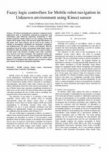
Optimal Design of the Fuzzy Navigation System for a Mobile Robot Using Evolutionary Algorithms Regular Paper
Abraham Meléndez1, Oscar Castillo1,*, Fevrier Valdez1, Jose Soria1 and Mario Garcia1 1 Tijuana Institute of Technology, Tijuana, México * Corresponding author E-mail:
[email protected]
Received 28 Nov 2012; Accepted 18 Dec 2012 DOI: 10.5772/55561 © 2013 Meléndez et al.; licensee InTech. This is an open access article distributed under the terms of the Creative Commons Attribution License (http://creativecommons.org/licenses/by/3.0), which permits unrestricted use, distribution, and reproduction in any medium, provided the original work is properly cited.
Abstract This paper describes the optimization of an integration block within the proposed navigation control system for a mobile robot. The control blocks that the integrator will combine are two Fuzzy Inference Systems (FIS) in charge of tracking and reaction control, respectively. The integrator block is called a Weighted Fuzzy Inference System (WFIS) and assigns weights to the responses of each behaviour block, to combine them into a single response. Keywords Fuzzy Control, Genetic Algorithms, Mobile Robots, Navigation
1. Introduction The use of mobile robots has increased over the last few decades in many areas, from industrial work to research and household uses and one reason for this is that they have proved useful in each of these areas, from doing a very specific task to carrying out on‐going monotonous chores they help their human counterpart be more productive and efficient. Also, another reason for this increase and why we are seeing them in more common places is that as hardware technology moves forward and www.intechopen.com
develops more capable robots can be designed and manufactured at a lower cost. The mobile robot needs to move around its environment and this is why a great deal of research has been invested in testing them with control systems that allow the robots to navigate on their own. Different methodologies have been applied, from traditional control such as PD, PID [4, 9] to soft computing methods like Fuzzy Logic [10, 25, 13, 17, 15, 18, 12, 11, 21, 5, 19, 20], Neural Networks [11] and hybrid networks [6, 23, 24]. In this paper, a navigation control system has been designed to combine two key behaviours that are considered to be required for any navigation control system in a mobile robot. The first one is a tracking controller; this is an obvious one since there is no point in having a navigation system on a robot, that cannot travel to a desired location. The second one is a reactive controller, which we considered to also be of great importance, since the tracking controller can get the robot to the destination, but only in a situation where there are no obstacles present in the robots path.
IntFevrier J Adv Robotic Sy, 2013, 139:2013 Abraham Meléndez, Oscar Castillo, Valdez, Jose Soria Vol. and 10, Mario Garcia: Optimal Design of the Fuzzy Navigation System for a Mobile Robot Using Evolutionary Algorithms
1
The reactive controller is for those cases where an obstacle free path cannot be guaranteed; this is where the reactive controller will do its work, initiating a behaviour that will make the robot react to any type of obstacle so that the robot can continue on its journey. In this paper we describe an integration method for these two controls as part of the complete Navigation Control System. The control blocks are type‐1 and type‐2 fuzzy inference systems and a general GA (Genetic Algorithm) is applied to the optimization of each of the controller blocks with a specific fitness function for each part that will evaluate the corresponding individual performance. In related work Cupertino et al. [8] developed a Fuzzy Controller for a mobile robot, based on 3 FLCs (Fuzzy Logic Controller) and one Fuzzy Supervisor that was in charge of determining which FLC behaviour would be active. In this system the FLCs are type‐1 and the Fuzzy Supervisor mainly acts as a switch. In our proposed method the Fuzzy Integrator acts more like a fusion block. Coupland et al. [7] proposed a type‐2 Fuzzy Control for a Mobile Robot, which is based on Payton et al.’s [22] Command Fusion, where the idea is that a behaviour should work with others to find a mutually beneficent solution, where each behaviour takes into consideration every possible output with its corresponding activation value (positive or negative) and a “winner takes all” network is used to select the winning responses for each behaviour. Coupland suggests using two FISs, one for goal seeking and another for obstacle avoidance. The activation value for each of the FIS outputs will be a fuzzy set that will be sent to the command fusion block to be defuzzifed into a crisp value. This crisp value will then be sent to the Actuator block, which is an advantage of our proposed control that integrates the two behaviours. The control navigation of mobile robots is a topic that has been extensively investigated over the years. The method proposed in this paper is based on the idea that separation and cooperation between key behaviours produces a better result than the use of a single behaviour, which differs from previous approaches from the integration perspective carried out by a FIS that is in charge of the weighted system and will assign a weight to each response from each controller by each control step that is combined to obtain a unified single response to the robot. This paper is organized as follows, In Section 2 we describe the mobile robot used in these experiments. Section 3 describes the development of the evolutionary method. Section 4 shows the simulation results. Finally, Section 5 shows the Conclusions. 2. Mobile Robot The particular mobile robot considered in this work is based on the description of the simulation toolbox for 2
Int J Adv Robotic Sy, 2013, Vol. 10, 139:2013
mobile robots [26], which assumes that the robot is wheeled and consists of one conventional, steered, unactuated and not‐sensed wheel and two conventional, actuated and sensed wheels (conventional wheel chair model). This type of chassis provides two DOF (degrees of freedom) locomotion by two actuated conventional non‐steered wheels and one unactuated steered wheel. The Robot has two degrees of freedom (DOFs): y‐ translation and either x‐translation or z‐rotation [26]. Fig. 1 shows the robot’s configuration. It has two independent motors located on each side of the robot and one castor wheel for support located at the front of the robot.
Figure 1. Kinematic coordinate system assignments [26]
The kinematic equations of the mobile robot are as follows. Eq. 1 describes the sensed forward velocity solution [26] ��� ��� � ���� � ��� � � ��� ��� ��
�� � �� ��� � ��� � (1) � ��
Eq. 2 describes the actuated inverse velocity solution [26]
�� �� � � � ��
�
����� ���
�
��� �� �� ��
���� � � ���� � �
��� ��� � � ��� � (2) �� �
Under the Metric system this is defined as: � ��� , ��� Translational velocities [ � ], ���
��� Robot z‐rotational velocity [
�
��
],
���
��� , ��� Wheel rotational velocities [
�
],
� Actuated wheel radius [m], �� , �� Distances of wheels from robotʹs axes [m]. 3. Navigation Control System
The proposed control system consists of three main fuzzy blocks, two that are behaviour based and another one that is in charge of response integration. The behaviours are reactive tracking blocks and each one will provide a specific behaviour that will be combined into one response by the integration block. Each behaviour block is in charge of its own task, the problem is that they seem to be in conflict with each other when an unexpected obstacle arises, because if when the route is planned obstacles are present then the route can www.intechopen.com
be designed to avoid them, but when there are obstacles that are unexpected the two behaviours contradict one another; one is designed to avoid the object and the other to keep the robot on its track. The most common solution is to just switch between controllers when needed. However, this approach is not very efficient due to the lack of awareness the two blocks have of each other. In some cases the reactive controller will effectively keep the robot from the collision but it may redirect the robot farther away from its destination to a point where the tracking controller can no longer find its way back to the reference. In other cases the tracking controller can guide the robot straight into the obstacle if the reactive controller is not activated in time. The proposed system for control navigation will always have both controls active, combining their responses and generating the movement of the robot. The integration is achieved with another fuzzy block called WFIS [15] (Weight‐Fuzzy Inference System). What this controller does is assign response weights to each of the controllers’ crisp response values. The inputs are gathered from the information that is collected from the robot (sensors) or the environment by means such as cameras and from this we can create a knowledge rule base to give higher activation values to the response we want to take the lead on the robot movement. One example of this rule is the following: (if Front_Sensor_Distance is Close Then TranckingWeight is Medium and ReactiveWeight is Medium). Both of our controls provide right and left motor speed and we combine each one with the weight given by the WFIS block. Figure 2 shows the proposed navigation control.
The purpose of using an evolutionary method is to find the best possible controllers of each type, which can be obtained using the GA because it searches along the solution space, combining the attributes from the best controllers to generate new ones. This concept was taken from the building blocks theory. The idea was to optimize the parameters in the Membership Functions, also the number of Membership Functions, and this means also optimizing the number of rules ‐ making this a multi objective problem. For this we will take advantage of the HGA (Hierarchical Genetic Algorithm) intrinsic characteristic to solve multi objective problems. The work of the GA was divided in two main modules, one that handles all the operations related to selection and chromosome manipulation, which we use for all our controllers, the other module is one where we evaluate the performance of each chromosome and this part is different in each case. With this approach we utilize the generality of the GA and have a specific evaluation method for each controller. Figure 3 shows the 2 main modules.
Figure 3. Genetic Algorithm process
The GA module is in charge of initializing the population, selecting the chromosomes that will be used for the genetic operations and letting the Evaluation Module know which chromosomes are ready to be evaluated and then reinserting them to the population pool. 4.1 Chromosome Encoding
Figure 2. Navigation Control System [15]
4. Genetic Algorithms The Genetic Algorithm (GA) was applied to each of the design problems of finding the best fuzzy reactive and tracking controllers [16]. However, this paper will only focus on the WFIS controller. www.intechopen.com
Each individual in the population will represent a FIS controller, each of which will be encoded with a vectorial structure that will have “n” main sections, one for each variable (input and output). Each main section will contain 2 subsections (control genes and connection genes). The section and subsection sizes depend on the controller that they represent. 4.2 Reactive Controller The function of the reactive controller is to give the same ability that we apply when we are driving, that is to react
Abraham Meléndez, Oscar Castillo, Fevrier Valdez, Jose Soria and Mario Garcia: Optimal Design of the Fuzzy Navigation System for a Mobile Robot Using Evolutionary Algorithms
3
to unexpected situations, traffic jams, stop lights, etc., but with a more basic ability and in a more simple situation. A forward moving behaviour response from the control is desired. The objective is to guide the robot through a maze, avoiding any collision. It’s not our objective to optimize the robot to find the maze exit, we use a maze to optimize the reactive control because of the characteristics it offers to the simulation, i.e., it is a closed space where the robot cannot easily wander off and each wall is considered to be an obstacle to the robot that it must avoid while it moves around. The FISs are interval Mamdani type‐1 fuzzy systems [26], each consisting of three inputs, which are the distances obtained by the robot’s sensors described in Section 2 and two outputs that control the velocity of the servo motors on the robot. All of this information is encoded into each chromosome. 4.3 Tracking Controller The tracking controller has the responsibility of keeping the robot on the correct path, when a reference is provided it will move the robot to the reference and keep it on track. This will allow the robot to move from point A to B. The controller will work by keeping the error (Δ℮p, Δθ) to a minimum value, which represents the error relative to the position and the error relative to the orientation of the front of the robot to a minimum value. The fuzzy system is a Mamdani type‐1 FIS and consists of two inputs that are (Δ℮p, Δθ) and two outputs that control the velocity of the servo motors on the robot.
4.4 WFIS Controller The goal of the Weighted Fuzzy Inference System (WFIS) control is to appropriately combine the 2 behaviours of tracking and reaction and obtain a new global behaviour that resembles the human skills that are applied when driving, that is to react to unexpected objects etc., but in a more general way. A forward moving behaviour response from the global control is needed in most cases. The goal is to guide the robot through the reference avoiding any collision with any obstacle that arises. It’s not our main objective to optimize the robot to find the maze exit, we needed a closed space where the robot cannot easily wander off and each wall is considered an obstacle to the robot that it must avoid while it moves around. The FISs are Mamdani fuzzy systems [14], each consisting of three inputs, which are the distances obtained by the robots sensors described in Section 2 and two outputs that are the weights that will be used to integrate the responses of the other two controllers. All this information is encoded into each chromosome. 4.5 Type‐1 Fuzzy Weight Controller Chromosome Architecture The control genes consist of 5 bit vectors, which will indicate which fuzzy membership is or is not active. The connection genes are divided into five subsections, five is the maximum number of membership functions that are allowed per variable, each of which can be a trapezoidal or triangular membership function. Each of these subsections is divided into two sections, one that indicates the type of the membership function and the other the parameters for the function (see Figure 4).
Figure 4. Fuzzy controller inputs ℮p, ℮θ
Figure 5. Type‐1 WFIS Controller Chromosome Architecture
4
Int J Adv Robotic Sy, 2013, Vol. 10, 139:2013
www.intechopen.com
4.6 Fuzzy Rules
The rule population consists of a different and separated population for each controller with respect to the control population, this is because the optimization procedure is totally different, but they are tightly related because the number of active rules depends on the number of active membership functions. In order to optimize the fuzzy rules we have a population of all the possible subsets, with the one restriction that the number of active membership functions must be the same. With Equation 3 we obtain the size of the fuzzy rules population, where m, n, p represents the maximum number of membership functions we allow for the input variables and k is the maximum number of membership functions for the output variables. In our case (m=n=p=k=5) Equation 3 gives a total of 625 fuzzy rules subsets.
Where h�i,j,q,r,s� is the consequent of the rule that has i, j, q, r, s. active membership functions, ∆r and ∆s represent our shift operator, with a probability of 0.01.
rp=m*n*p*k (3)
In this case, we will only have one active subset that can match the fuzzy controller, which has the following membership functions active: Sa, b, c, d, e. Where a, b, c are the number of active membership functions for the input variables and d, e for the output variable. We use an index table for each of the fuzzy subsets (see Table 1). Input Input Input Output Output
S1,3,2,2,2=
01
02
03
01
02
1
1
1
1
1
1
1
2
1
1
1
2
1
1
1
1
2
2
2
1
1
3
1
1
2
1
3
2
2
1
Table 1. Rules Index Table.
A Special mutation operator is applied (Equation 4) to find the optimal fuzzy rule set for the reactive controller. The shift operation that is used changes the consequent part of the rule.
h(i,j,q,r,s)=h(i,j,q,(r+∆r),(s+∆s)) (4)
4.7 Objective Function The GA will generate individuals that will need to be evaluated and assigned a crisp value that will represent the controller performance in each of the criteria that we want to improve. For this, we need to provide the GA with a good evaluation scheme that will penalize unwanted behaviours and reward with higher fitness values those individuals that provide the performance we are looking for in our controller. If we fail to provide a proper evaluation method we can guide the population to suboptimal solutions or no solution at all. 4.7.1 Reactive Controller Objective Function The criteria used to measure the Reactive controller performance are the following: Covered Distance Time used to cover the distance Battery life. A Fitness FIS will provide the desired fitness value, adding very basic rules that reward the controller that provides longer trajectories, smaller times and higher battery life. This seems like a good strategy that will guide the control population into evolving and provide the optimal control. However, this strategy on its own is not capable of doing just that, it needs to have a supervisor of the robots trajectory to make sure it is a forward moving trajectory and that it does not contain looping parts. For this, a Neural Network (NN) is used to detect cycle trajectories that don’t have the desired forward moving behaviour by giving them a low activation value and giving a higher activation value to the ones that are cycle free. The NN has two inputs and one output and two hidden layers.
Figure 6. Fitness Function for The Reactive Controller www.intechopen.com
Abraham Meléndez, Oscar Castillo, Fevrier Valdez, Jose Soria and Mario Garcia: Optimal Design of the Fuzzy Navigation System for a Mobile Robot Using Evolutionary Algorithms
5
The evaluation method for the reactive controller integrates both parts the FIS and the NN. The fitness value for each individual is calculated with Equation 5. Based on the response of the NN, the peak activation value is set to 0.35, meaning that any activation lower than 0.35 will penalize the fitness given by the FIS.
�� � ���� ��� � ���� (5) ��� ��� � ����
��� � � �
Where: fi Fitness value of the i‐th individual, fv Crisp value out of the fitness FIS, nnv Looping trajectory activation value.
4.7.2 Tracking Controller Objective Function The Tracking controller performance is measured with the root mean squared error (RMSE) between the reference and the robot’s trajectory. We apply the test three times and take the average. In each of the three tests the robot and the reference vertical position is random, but it is ensured that on one test the robots vertical position is above the reference and on another test is below it. We do this to ensure the controller works properly in any case where the robot may need it when it is above or below.
Figure 7. Fitness Function for the Reactive Controller
4.7.3 WFIS Controller Objective Function. The WFIS controller performance is measured based on the RMSE between the reference and the actual robot’s trajectory. We apply the test three times and take the average to improve the significance of the value. On each of the three tests the robot and the reference vertical
position is random, but we ensure that in one test the robot vertical position is above the reference and in another test is below it. This is done to ensure the controller works properly in any case, where the robot may need it when it is above or below (Figure 8).
Figure 8. Fitness Functions for the WFIS Controller
4.8 Optimization Toolbox A Toolbox is designed to optimize type‐1 and type‐2 FIS controllers. It can customize the number of inputs and outputs and the maximum and minimum number of 6
Int J Adv Robotic Sy, 2013, Vol. 10, 139:2013
Fuzzy memberships allowed and the basic parameters of the Genetic Algorithm, such as number of generations, population replacement mutation and crossover rate and the type of selection. Figure 9 shows the initial screen in the toolbox. www.intechopen.com
As the GA is running a generation graph is plotted with the best individual found and a display area with all the population data. Figure 10 shows the final output when using the toolbox for optimizing the type‐2 fuzzy system using the genetic algorithm.
Figure 9. Initial screen of the optimization toolbox
Figure 10. Simulation Results with the toolbox
5. Simulation Results For the simulation experiment the GA and the evaluation process were separated into two different parts, the generic GA process was developed in the C# language with .net 4, where a GA and Fuzzy System library were created with a GUI to setup the GA parameters. There the GA operations and cycle were run and the FIS was created. When a chromosome is ready to be evaluated it lets Matlab know and a modified version of the Simulation toolbox for mobile robots [26] is used to run each test, where the performance is measured and a Fitness value is returned to the GA process. Communication between both processes is achieved using a SQL server queue table.
For the type‐1 reactive controller, a GA was setup with a high number of generations and a low population size. This is because of the large solution space. The reasoning behind this decision is that with a relatively small group of individuals focused sections of the solution will be covered and the robot can move around the space. A constraint for inputs and outputs of a maximum of ten and a minimum of two FM was set. On the outputs another constraint was
Representation Population Size No. of Offspring Crossover Crossover Rate Mutation Mutation Rate Generation Selection Rank
5.1 Reactive Controller
www.intechopen.com
set, that the outputs had to be the same. The evaluation as described in Section 4 is based upon each individual performance in the particular maze problem.
1 2 3 4 5 6 7 8 9
Membership Chromosome Fuzzy Rule Control Chromosome Connections Genes Genes Binary Real Number Integer 20 5 One Point One Point 1.0 1.0 Bit Random Mutation Shift index Mutation operation 0.02 0.02 GA Parameters 8000 Roulette Wheel with Ranking Results Fitness Active FM’s Active Rules (S1+S2+S3+M1+M2) 0.4895 (4+3+2+3+3)=15 24 0.4895 (4+3+2+3+3)=15 24 0.4895 (4+3+2+3+3)=15 24 0.4895 (4+3+2+3+3)=15 24 0.4895 (4+3+2+3+3)=15 24 0.4895 (4+3+2+3+3)=15 24 0.4895 (4+3+2+3+3)=15 24 0.4895 (4+3+2+3+3)=15 24 0.4895 (4+3+2+3+3)=15 24
Table 2. Summary of Reactive Control Results.
Abraham Meléndez, Oscar Castillo, Fevrier Valdez, Jose Soria and Mario Garcia: Optimal Design of the Fuzzy Navigation System for a Mobile Robot Using Evolutionary Algorithms
7
Table 2 shows the GA configuration and the top nine Results, where we have the fitness value and the number of membership functions of each input and output. Where S represents the inputs and indicates the sensor number and M represents the outputs and indicates the motor number and the total rules that are active on each controller 5.2 Tracking Controller Table 3 shows the GA configuration and the top nine Results, where we have the fitness value and the number of membership functions of each input and output. ℮p and Δθ represent the inputs and indicate the error on the position and orientation respectively and M is the output and indicates the motor number and the total rules that are active on each controller. Representation Population Size No. of Offspring Crossover Crossover Rate Mutation Mutation Rate Generation Selection Results Rank
1 2 3 4 5 6 7 8 9
Membership Chromosome Control Connections Genes Genes Binary Real Number 20 2 One Point One Point 1.0 1.0 Bit Mutation Random Mutation 0.02 0.02 GA Parameters 4000 Roulette Wheel with Ranking
Fitness
Active Rules
0.1907 0.2021 0.2023 0.2091 0.2124 0.2125 0.2182 0.2199 0.225
Active FM’s (℮p+ eθ +M1+M2) 5+4+4+3=16 5+4+4+3=16 5+4+4+3=16 5+4+4+3=16 7+2+4+5=18 5+4+4+3=16 6+2+5+2=15 5+4+4+3=16 5+4+4+3=16
Fuzzy Chromosome
Rule
Integer Shift index operation
cover focused sections of the solution and the robot can move around the search space. A constraint for inputs and outputs of a maximum of ten and a minimum of two FMS was set. The evaluation, as described previously in Section 4, is based upon each individual performance in the particular maze problem. Membership Chromosome Control Connections Genes Genes Representation Binary Real Number Population Size 10 No. of Offspring 3 Crossover One Point One Point Crossover Rate 1.0 1.0 Bit Mutation Random Mutation Mutation Mutation Rate 0.02 0.02 GA Parameters Generation 1500 Selection Roulette Wheel with Ranking Results Active FM’s Rank Fitness (S1+S2+S3+W1+W2) 1 0.2746 3+5+2+2=12 2 0.4170 2+4+3+2=11 3 0.4553 3+5+2+2=12 4 0.4740 3+5+2+2=12 5 0.4856 2+4+2+2=10 6 0.5043 2+4+2+2=10 7 0.5197 2+4+2+2=10 8 0.5233 2+4+2+2=10 9 0.5277 2+4+2+2=10
Fuzzy Rule Chromosome Integer
Shift index operation
Active Rules 15 8 15 15 8 8 8 8 8
Table 4. Summary of Type‐1 WFIS Results
20 20 20 20 14 20 12 20 20
Table 3. Summary of Tracking Results.
5.3 WFIS Controller
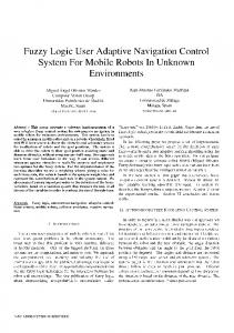
Table 4 shows the GA configuration and the top nine Results, where we have the fitness value and the number of membership functions of each input and output. S represents the inputs and indicates the sensor number and W represents the outputs and indicates the Weight number and the total rules that are active on each controller. Figure 11 shows the three tests carried out during the evaluation process of the GA. The red line is the reference, the blue dotted line is the robot path on each run and the grey squares are obstacles located around the reference path.
For designing the WFIS controller, a GA was similarly setup with a high number of generations and a low population size. This is because of the large solution space in this case. The reasoning behind this decision is that with a relatively small group of individuals it will
8
Int J Adv Robotic Sy, 2013, Vol. 10, 139:2013
www.intechopen.com
Figure 11. WFIS Controller Results www.intechopen.com
Abraham Meléndez, Oscar Castillo, Fevrier Valdez, Jose Soria and Mario Garcia: Optimal Design of the Fuzzy Navigation System for a Mobile Robot Using Evolutionary Algorithms
9
6. Conclusions In this paper we have been able to optimize the Fuzzy Reactive and Tracking controllers and the WFIS controllers and develop a toolbox to optimize the fuzzy inference system. The results obtained from the proposed control system show good performance in integrating two behaviours into a single response that was able to take the robot to the reference and avoid any collisions with the obstacles present on the map. Future work will consist of the optimization of the WFIS based on a type‐2 fuzzy system. 7. Acknowledgment We would like to express our gratitude to CONACYT and the Tijuana Institute of Technology for the facilities and resources granted for the development of this research. 8. References [1] Aceves A., Aguilar J. ”A Simplified Version of Mamdani’s Fuzzy Controller The Natural Logic Controller”. IEEE Transactions on Fuzzy Systems, Vol 14, No 1, pp: 16 – 30, 2006. [2] Aguilar L., Melin P., Castillo O. ”Intelligent Control of a stepping motor drive using a hybrid neuro‐fuzzy ANFIS approach”. Applied Soft Computing, Vol 3, No 3, pp: 209‐219, 2003. [3] Astudillo L., Castillo O., T. Aguilar. L. ”Intelligent Control of an Autonomous Mobile Robot Using Type‐2 Fuzzy Logic” Engineering Letters, Vol 13, No 2, pp: 93‐97, 2006. [4] Bell M., Toriu T., Nakajima S. ”Image‐Based Robot Map Building and Path Planning with an Omnidirectional Camera Using Self‐Organising Maps”. International Journal of Innovative Computing, Information and Control, pp: 3845‐3852, 2011. [5] Castillo O., Melin P. ”New fuzzy‐fractal‐genetic method for automated mathematical Modeling and Simulation of Robotic Dynamic Systems”, IEEE, International Conference on Fuzzy Systems 2, pp: 1182‐118, 1998. [6] Castillo O., Melin P. ”New fuzzy‐fractal‐genetic method for automated mathematical Modeling and Simulation of Robotic Dynamic Systems”, IEEE, International Conference on Fuzzy Systems 2, pp: 1182‐118, 1998. [7] Coupland S. ”Type‐2 Fuzzy Control of a Mobile Robot”, PhD Transfer Report, De Montfort University, UK, 2003. [8] Cupertino F., Giordano V., Naso D., Delfine L. ”Fuzzy control of a mobile robot”, Robotics & Automation Magazine, IEEE, pp: 74‐81, 2006. [9] Fate M. ”Robust Voltage Control Of Electrical Manipulators In Task‐Space”. International Journal 10 Int J Adv Robotic Sy, 2013, Vol. 10, 139:2013
of Innovative Computing, Information and Control, pp: 2691‐2700, 2010. [10] Ishikawa S. ”A Method of Indoor Mobile Robot Navigation by Fuzzy Control”, Proc. Int. Conf. Intell Robot. Syst., Osaka, Japan, pp: 1013‐1018, 1991. [11] Klir G., Yuan B. ”Fuzzy Sets, Fuzzy Logic, and Fuzzy Systems: Selected Papers by Lotfi A. Zadeh”, Advances in Fuzzy Systems: Application and Theory, Vol. 6, World Scientific Publishing Company, 1996. [12] Kim C., Lee K. ”Robust Control of Robot Manipulators Using Dynamic Compensators under Parametric Uncertainty”. International Journal of Innovative Computing, Information and Control, pp: 4129‐4137, 2011. [13] Leyden M., Toal D., Flanagan C. ”A Fuzzy Logic Based Navigation System for a Mobile Robot”, Proceedings of Automation Symposium, 1999. [14] Mamdani E., ”Applications of fuzzy logic to approximate reasoning using linguistic synthesis. Proc. 6th Int. Symp. on Multiple Value Logic, Utah State University, pp: 196‐202, 1976. [15] Melendez A., Castillo O., Soria J. ”Reactive and Tracking Control of a Mo‐bile Robot in a Distributed Environment Using Fuzzy Logic”, FUZZ, IEEE International Conference, pp: 1‐5, 2010. [16] Melendez A., Castillo O., Melin P. ”Evolutionary Optimization of the Fuzzy Controllers in a Navigation System for a Mobile Robot”, International Journal of Innovative Computing, Information and Control, International Journal, (In press). [17] Meléndez A., Castillo O., Soria J. ”Reactive Control of a Mobile Robot in a Distributed Environment Using Fuzzy Logic”, Fuzzy Information Processing Society, 2008. NAFIPS 2008. Annual Meeting of the North American Vol 1,No 19‐22, pp: 1 – 5, 2008. [18] Melin P., Castillo O. ”Intelligent Systems with Interval Type‐2 Fuzzy Logic”, International Journal of Innovative Computing, Information and Control, pp: 771‐784, 2008. [19] Melin P., Castillo O. ”Intelligent control of aircraft dynamic systems with a new hybrid neuro‐fuzzy fractal approach”, Information Sciences, Vol 142, No 1‐4, pp: 161‐175, 2002. [20] Melin P., Castillo O. ”Adaptive Intelligent control of aircraft systems with a hybrid approach combining neural networks, fuzzy logic and fractal theory”, Applied Soft Computing, Vol 3, No 4, pp: 353‐262, 2003. [21] N.Pishkenari H., H. Mahboobi S., Meghdari A. ” On the Optimum Design of Fuzzy Logic Controller for Trajectory Tracking Using Evolutionary Algorithms”, Cybernetics and Intelligent Systems, 2004 IEEE Conference on, Vol 1, pp: 660‐ 665, 2004. [22] Payton D. W., K. Rosenblatt J., M. Keirsey D. ” Plan guided reaction”, Systems, Man and Cybernetics,
www.intechopen.com
IEEE Transactions on, Vol 20, No 6, pp: 1370 – 1382, 1990. [23] Shafiei S., Soltanpour M. ”Neural Network Sliding‐ Mode‐PID Controller Design for Electrically Driven Robot Manipulators”, International Journal of Innovative Computing, Information and Control, pp: 511‐524, 2011. [24] Shafiei S., Soltanpour M. ”Robust Task‐Space Control of Robot Manipulators under Imperfect Transformation of Control Space”, International
Journal of Innovative Computing, Information and Control, pp: 3949‐3960, 2009. [25] Thomson A., Baltes J. ”A path following system for autonomous robots with minimal computing power”, University of Auckland, Private Bag 92019, Auckland, New Zealand, Technical Report, 2001. [26] ”Mobile robotics toolbox for Matlab 5” http://www.uamt.feec.vutbr.cz/robotics/simulations/ amrt/simrobot_en.html, 2001
www.intechopen.com
Abraham Meléndez, Oscar Castillo, Fevrier Valdez, Jose Soria and Mario Garcia: Optimal Design of the Fuzzy Navigation System for a Mobile Robot Using Evolutionary Algorithms
11