One may however note that, in many applications, the ... multirate filter bank design problem. ..... [5] N. J. Fliege, Multirate Digital Signal Processing, John. Wiley ...
In a district heating plant low-quality cheap oil could be burnt in ... to do their best in order to avoid such fossil heat sources. If it was ..... common laptop computer.
Sep 4, 2013 - The multiobjective design of digital filters using spiral optimization technique is considered in this paper. This new optimization tool is a ...
computer program to the design of optimal finite wordlength FIR dig- ital filters is ... 1) they are successful only for filters with a small number of coefficients ...
Wu-Sheng Lu, Fellow, IEEE, and Takao Hinamoto, Fellow, IEEE. AbstractâIn this ..... for odd-order denominators), then, as one may expect, the con- straint in ...
decreases to improve the search convergence of the genetic algorithm. m p. ( ) kkk kkk m e e kp. /) ..... Engineering at Purdue University, West Lafayette, Indiana,.
prescribed frequency domain (FD) specification. It is shown that the FD error vector is linearly re- lated to the 2-D numerator coefficients whereas the relationship ...
Jun 15, 2012 - Author Keywords. Tangible user interfaces, Digital manipulatives, Education, .... therefore important to develop flexible tools and applications that ..... colored i-Cubes together and listening to its immediate rendition. Melodic ...
Jun 15, 2012 - Wooi Boon Goh L.L.Chamara Kasun Fitriani Jacquelyn Tan Wei Shou. School of Computer ..... robin fashion. The receiver circuit latches a ...
A Digital-Based Optimal AVR Design of Synchronous Generator ... Excitation control of generators is a very ... good excitation control, indeed, has proven to be ...... website: http://www.engin.umich.edu/class/ctms/ind ex.htm. [15] Franklin G. F. ...
Nov 28, 2017 - ZHAO Yun-wei1, ZHU Zi-qiang1, LU Guang-yin1, LI Jian-hui2. 1. School of Geosciences and info-Physics, Central South University, ChangSha.
L. Zhao, C.H. Ham, Q. Han, T.X. Wu, L. Zheng, K.B. Sundaram, J. Kapat and L. Chow. Abstract: A ... rotor and only low eddy-current loss in the stator and rotor,.
Home office: Laptop computer with word processing capability and Internet connectivity. Access to reliable, fast Interne
Keywords: Lossy LP-BP transformation, impedance taper- ... BP transformation carried out by component substitution .... RC LP-BP network transformation. 376.
Jun 19, 2006 - sis and design optimization model for fuel cell vehicles that can be applied to both ..... is a version of the Vehicle Engine SIMulation (VESIM) model, developed at the ... order to make computation affordable. The performance ..... a
lEEE TRANSACTIO3 1S ON AUDIO AND ELECTROACOUSTICS, VOL. AU-20, NO. 4, OCTOBER 1972 ock Rea. Digital Filters. CHARLES S. BURRUS.
Nov 2, 2010 - heads and hearts who taught by way of love and devotion. .... 73. 7 Moments and centres of mass: preliminaries. 75. 7.1 Informal definitions . ...... Cleary, the same argument will not work for a block set such as c1,100.
as a flexible criterion that, depending on the application, can offer many choices for ... D(v, b, k) be the class of al
May 29, 2014 - The users are assigned to resource blocks. A transmission may use multiple resource blocks sched- uled over frequency and time. In our model ...
Mar 27, 1990 - fingers is tense and is particularly sensitive to pain. Two different ... digital block whilst those born in an 'even' year received local infiltration.
Regressive G-Optimal Design (LRGOD) for relevance feed- back image retrieval. Our assumption is that for each im- age, its label can be well estimated based ...
Balra J. Singh. Department of Electronics and Communication Engineering,. Giani Zail Singh Punjab Technical University Campus, Bathinda-. 151001, Punjab ...
in response to necessary blast and ballistics requirements. Thus, most research and development has focused on experimen
by finding essentially physical arguments to find formulas for other sums of powers, combinatorial identities and Fibonacci summation formulas. iv ...
is then processed and provides L samples of the output signal. (L 6 M and M â L is ... Let us note x the input block and y the output block. The ... On Signal Processing, Vol. 52, No. ... eigenanalysis, is used in [9] for the design of multirate filters. ...... Circuits and Systems - II: Analog and Digital Signal Processing, Vol. 43,. No.
1
IEEE Trans. On Signal Processing, Vol. 52, No. 7, pp. 1964-1974, July 2004 (draft version)
Optimal Design of Transform-Based Block Digital Filters using a Quadratic Criterion Gilles Burel Laboratoire d’Electronique et Systèmes de Télécommunications Université de Bretagne Occidentale, CS 93837, 29238 Brest cedex 3, France phone: +33.2.98.01.62.46 fax: +33.2.98.01.63.95 email: [email protected] (IEEE member 41296799) EDICS: 2-FILT Abstract— Block Digital Filtering is a powerful tool to reduce the computational complexity of digital filtering systems. However, due to their block structure, Block Digital Filters (BDF) are time-varying linear systems, hence their design is not easy. The most widely spread approaches to BDF design consist in constraining the BDF to be time-invariant (by restricting the design process to a specific subset of possible solutions) and then using conventional filter synthesis techniques. In this paper, we do not restrict the design process and we propose a simple and optimal matrixoriented approach to optimize the BDF coefficients. Furthermore, the proposed approach takes profit of the structure of transform-based Block Digital Filters to considerably reduce the computational complexity and memory requirements of the design process. Experimental results confirm that, as expected, the obtained global distortion is lower than the distortion obtained with a traditional technique such as overlap-save. Keywords— Block Digital Filters, Optimum Design, Aliasing, TimeVarying systems, Overlap-Save
I. I NTRODUCTION A. Principle of Transform-Based Block Digital Filters Transform-based Block Digital Filtering is well known for its ability to reduce the computational complexity of digital filtering systems. As shown in Figure 1, the input signal is divided into (possibly) overlapping blocks of M samples. Each block is then processed and provides L samples of the output signal (L 6 M and M − L is even to preserve symmetry).
Fig. 1. Block Digital Filtering
Let us note x the input block and y the output block. The
system is linear, hence there is a matrix A such that: y = Ax
(1)
This matrix is decomposed as follows: A = STM−1 GTM
(2)
where TM is the matrix of a transform for which there exists a fast algorithm, such as the Discrete Fourier Transform (DFT) or the Discrete Cosine Transform (DCT), for instance. G is a matrix whose elements are chosen in order to obtain a frequency response close to the desired one (usually, G is a diagonal matrix). S is a selection matrix, which selects L values out of M (the L samples in the middle of the obtained M-points block). For instance, if L = 2 and M = 4, we have: t u 0 1 0 0 S= (3) 0 0 1 0 B. Usual approaches The block sizes and the transform being chosen (usually based on hardware or software complexity considerations), design of a Block Digital Filter (BDF) consists in optimizing the coefficients of matrix G. The most widely used approaches to BDF design consist in constraining the system to be time-invariant by restricting the optimization of matrix G to a specific subset of possible solutions and then in using conventional filter synthesis techniques. The most well known and widely used approach to BDF design is overlap-save ([8], p. 558), while there exist other efficient approaches [5] to ensure that the obtained BDF is time-invariant. In the overlap-save approach matrix G is diagonal, and TM is the DFT matrix. This choice provides two advantages: first, there exists a fast algorithm for the transform, and, second, the coefficients of matrix G can be interpreted as weights applied to the frequency representation of the input block. The diagonal of G is the DFT of the impulse response of a finite length digital filter. Hence, the BDF computes the DFT of the input block, multiplies the result by the diagonal values of G, computes an inverse DFT, and selects L samples out of M. Due to the properties of the DFT, this is equivalent to performing a
2
IEEE Trans. On Signal Processing, Vol. 52, No. 7, pp. 1964-1974, July 2004 (draft version)
circular convolution between the impulse response of the finite length digital filter and the input block, and selecting L samples out of M. If this impulse response is restricted to the interval −(M − L)/2 to +(M − L)/2, a circular convolution is equivalent to a linear convolution, as far as the L selected samples are considered. The consequence is that there is no block effect in the output signal, and thus the system is time-invariant and can be designed by traditional techniques. Confinement of the impulse response to the interval −(M − L)/2 to +(M − L)/2 is required to ensure that the BDF is timeinvariant. However, as we will see with the experimental results, this confinement may seriously degrade the frequency response of the BDF. Another approach is straightforward (here again, G is diagonal and TM is the DFT matrix): the diagonal elements of matrix G are directly obtained by sampling the desired BDF frequency response. This is justified by the fact that the diagonal elements of G can be interpreted as weights applied to the frequency representation of the input block. The problem is that the obtained BDF is not time-invariant anymore. Hence, the output signal contains not only a linear time-invariant filtered version of the input signal, but also aliasing components [10]. Powerful and general methods to study and predict the aliasing distortion have been developed in the context of filters banks theory [10]. However, since in this article we focus on Transform-Based Block Digital Filters, and since our objective is low computational complexity, we will avoid the use of filters banks theory. C. Proposed approach Aliasing may be tolerated provided it remains low. In this paper, we propose a method to design BDF that takes into account both time-invariant and aliasing components. Hence, we no longer have to put strong restrictions on the elements of matrix G, as required by methods which need to ensure timeinvariance. Furthermore, our method is optimal with respect to a quadratic criterion. In the literature, few attempts were made to analyze the aliasing components (in comparison with attempts to propose methods to eliminate all aliasing components). To our knowledge, one of the most interesting tool is probably the bifrequency map [6] (see also [1] for the use of a bifrequency map to study the effects of multirate systems on the statistics of random input signals). This map graphically shows the time-invariant response of the BDF, as well as its aliasing components. The authors then derive an approach to optimally design a BDF, given a desired bifrequency map. An interesting alternative approach, based on eigenanalysis, is used in [9] for the design of multirate filters. Compared with these approaches, the originality of our work is that we focus on transform based filters, and take profit of the special structure of this kind of filters to derive fast and optimal synthesis methods. Other interesting features are: • Contrary to the bifrequency map, which is a continuous representation (hence needs to be discretized for actual use in design), our technique always remains in the discrete domain. • Our approach is based on elementary matrix computation only, hence it is easy to implement with modern mathematical tools, such as Matlab. We do not use filters banks theory, nor interpolation or decimation theory.
• In most widely occurring applications, the computational complexity and memory requirements of the optimization process are considerably reduced. The paper is organized as follows. In Section II we show how to compute the frequency response of a block digital filter using elementary matrix operations. Then in Section III, a quadratic criterion is defined and expressed using matrix notations. In Section IV we develop and explain the proposed optimization method. Experimental results are shown in Section V to illustrate the approach. Finally, a conclusion is drawn in Section VI.
II. F REQUENCY RESPONSE OF A B LOCK D IGITAL F ILTER Our objective in this Section is to obtain the output spectrum as a function of the input spectrum and of matrix A, using elementary matrix operations. First of all, let us give the notations that will be used throughout the article. A. Notations and definitions The definition of the Discrete Fourier Transform is well known, but the multiplicative factor may vary from one book to another. In the article, we will use the most “standard” definition. The N-points DFT is defined as: x(k) = and its inverse is: x(n) =
N −1 ;
x(n) e− j2π nk/N
(4)
n=0
−1 1 N; x(k) e j 2πnk/N N n=0
(5)
HN the matrix corresponding to the N-points We will note W √ HN / N its normalized version (W N is a DFT and W N = W HN unitary matrix). The element at row r and column c in W − j2πrc/N is e . Throughout the paper, we will use the notations below: x(n) the input signal and x(k) its DFT. y(n) the output signal and y(k) its DFT. a(n, m) the elements of matrix A. H n = n mod L c = (M + L)/2 d = (M − L)/2 In the next subsection, we will define an integer K which will be used throughout the paper and which is linked to the desired frequency resolution. We also define p(n, m) as follows: p(n, m) = a(n, n + d − m)
(6)
for 0 6 n 6 L − 1 and n + d − (M − 1) 6 m 6 n + d, and p(n, m) = 0 otherwise. Let us note: • P the L × K matrix whose elements are the p(n, m). It should be noted that the second index is considered modulo K : for instance, p(2, −3) is found at row 2 and column K − 3 in P. • P the L × K matrix obtained by computing the DFT of the rows of P • P the L × K matrix obtained by computing the DFT of the columns of P and dividing the result by L
3
IEEE Trans. On Signal Processing, Vol. 52, No. 7, pp. 1964-1974, July 2004 (draft version)
We will see that P has a crucial role because it represents the 2D frequency response of the BDF. We remind that, with complex data, the required number b c of real multiplications for a K -points FFT is K log2 K − 3 + 4 (see [7] p. 60), that is, approximately, K log2 K . Desired matrices will be noted using subscript d, such as P d → or Ad . We use the notation − u = vec(U ) for the operation which consists in concatenating the columns of matrix U in or→ der to build a vector − u . We also note U H the Hermitian transpose of matrix U . Finally, symbol ¡ stands for the Hadamard product between two matrices (i.e. multiplication element by element).
Thus, the output spectrum is: y(k) = =
y(n) =
M−1 ;
m =0
a(H n , m ) x(n − H n−d +m )
Let us note m = H n + d − m . We can write: y(n) =
Then:
H n; +d
m=H n +d−(M−1)
y(n) =
c−1 ;
a(H n, H n + d − m) x(n − m)
m=−(c−1)
p(H n , m) x(n − m)
(7)
(8)
(9)
where c was defined in subsection II-A. This equation shows that we have a periodically time-varying linear filter. Indeed, the filter coefficients depend on n, and it is a periodical dependence, because if we replace n by n+L we obtain the same coefficients. Since the indices are considered modulo K , we have: y(n) =
K −1 ;
m=0
p(H n , m) x(n − m)
(10)
Since a circular convolution can be computed as the inverse DFT of the product of the DFTs, we have: y(n) =
−1 nl 1 K; p(H n , l) x(l) e j2π K K l=0
(11)
nk
y(n) e− j2π K
n=0 K −1 ;
1 K
x(l)
l=0
K −1 ;
p(H n , l) e− j2π
n(k−l) K
(12)
n=0
Since K = bL we can write:
K −1 ;
p(H n , l) e− j2π
n=0
n(k−l) K
= =
B. Spectrum of the output signal In practice, the spectrum is always analyzed with a limited frequency resolution. Hence, we can consider that the signals are periodic, and note K the number of samples in a period. In the frequency domain, index k = 0, ..., K − 1 represents the normalized frequency 2πk/K . Therefore, choosing K is equivalent to choosing the frequency resolution. This does not mean, of course, that the method developed in the paper is restricted to periodic signals. What we say is that, given a frequency resolution, there is no approximation in considering the signal as periodic. In order to use the circular convolution properties of the DFT, and to obtain simple equations, we consider that the input signal (and, hence, the output signal) is periodic, with a period K = bL (b is the number of blocks in a period and we choose K such that b = K /L is an integer). We remind that L is the output block size (see Figure 1). Using equation 1, we can see that the output signal is:
K −1 ;
b−1 L−1 ; ;
p(s, l) e− j2π
(q L+s)(k−l) bL
q=0 s=0 L−1 ;
p(s, l) e− j 2π
s(k−l) bL
s=0
=b
L−1 ;
b−1 ;
e− j2π
q=0 rs
p(s, l) e− j 2π L
s=0
= K p(r, l)
3b−1 − j 2π (k−l) q b because q=0 e is null, except when (where r is an integer). Finally, we obtain: y(k) = p(0, k)x(k) +
(k−l) b q
L−1 ; r=1
(13) k−l b
p(r, k − br ) x(k − br)
= r (14)
The first term is the time-invariant part of the filter (it corresponds to the first row of P). The second term will be called “aliasing”. It is produced by the time-varying part of the filter. C. Summary To compute the output spectrum of a Block Digital Filter, one has to: 1. Compute matrix A = STM−1 GTM (this matrix has L rows and M columns), according to equation 2. 2. Place the elements of A into a matrix P with L rows and K columns (using equation 6 and considering the second index modulo K ). The rows of P represent the time-varying filter coefficients. 3. Compute matrix P by performing the DFT of the rows of P. The rows of P represent what might be called the time-varying frequency response. 4. Compute matrix P by performing the DFT of the columns of P and dividing the result by L. The first row of P represents the time-invariant frequency response and the other rows are the aliasing components. 5. Use equation 14 to compute the output spectrum. Now, let us express the relation between P and P using matrix notations. This will be useful for theoretical developments H and W used below have been defined in the sequel. Matrices W in subsection II-A. We have: HK because it is obtained by the DFT of the rows of • P = PW P. 1 H • P = LW L P because it is obtained by the DFT of the columns of P, followed by a division by L. Hence we have: U 1 H HK = K W L P W K P = WL P W (15) L L
4
IEEE Trans. On Signal Processing, Vol. 52, No. 7, pp. 1964-1974, July 2004 (draft version)
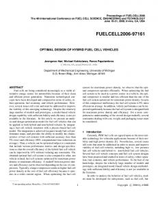
D. Illustration
value
1
desired frequency response
P 10
20
20
row
10
30
30
40
40 20
40 column
60
50
100 150 column
Pdoublebar
10
10
20
20
row
row
Pbar
30
30
40
40 50
0.5
100 150 column
50
100 150 column
Fig. 3. Matrices A, P, P and P
0 0
50
100
frequency index (k)
1 value
row
A
As an illustration, let us consider a Block Digital Filter with M = 64 and L = 48. The transform is the DFT and matrix G is diagonal. We have chosen K = 4L = 192 to obtain a frequency resolution 2π/192. Figure 2 shows the desired frequency response f (k) (the value is 1 between 48 and 80, and zero outside) and the diagonal of matrix G, obtained using the classical method: we consider that g(k, k), k = 0, ..., M − 1 represents the response at the normalized frequencies ω = 2πk/M. Then, since f (k), k = 0, ..., K − 1 represents the desired response at normalized frequencies ω = 2πk/K , the diagonal of G is obtained using a linear interpolation of the desired frequency response.
150
diagonal of matrix G
0.5 0 0
10
20
30
40
diagonal element
50
60
Fig. 2. Desired frequency response (top) and diagonal of matrix G (bottom)
Figure 3 shows matrices A, P, P and P. Each matrix element is represented by a gray value which is an increasing function of its modulus. Each row of P represents the impulse response at a given time, and we can clearly see that it is time-varying. Each row of P is the frequency response at a given time. We can see that the rows of P are not exactly identical: this means that the filter frequency response is time-varying. This yields to aliasing, which can be seen on matrix P. Indeed, the first row of P is the time invariant frequency response and the other rows are the aliasing components of the frequency response. Figure 4 shows a three-dimensional plot of this matrix. In the figure, the height is equal to the square root of the modulus of the matrix element. We can see that aliasing is not randomly distributed: it draws a typical pattern. III. Q UADRATIC CRITERION To evaluate the quality of a Block Digital Filter, we must define a criterion which measures the distance between the obtained output spectrum and the desired output spectrum. We will use a standard quadratic criterion (mean square error): K −1 ; 2 eM S = E (16) z(k) |y(k) − f (k)x(k)| k=0
Fig. 4. 3D view of matrix P (the height is the square root of the modulus of the matrix element)
This is the most widely used criterion, while other, more sophisticated, criteria exist (see [2][3] for instance). In the equation above, f (k) is the desired frequency response. The coefficients z(k) are weights which can be used to give a higher importance to some frequencies. The most frequent cases are: • All weights are equal to 1: this means that no frequency is privileged. This will be called the “unweighted” criterion. • Weights are binary (0 or 1): when they are equal to zero, this means “don’t care”. Usually, the frequencies with zero weight correspond to guard intervals.
Using equation 14 and usual hypotheses (input signal mod-
5
IEEE Trans. On Signal Processing, Vol. 52, No. 7, pp. 1964-1974, July 2004 (draft version)
elled as a white noise), we obtain: eM S =
K −1 ; k=0
−1 ; K; n n2 L−1 n n2 z(k) n p(0, k) − f (k)n + z(k) n p(r, k − br)n r=1 k=0
(17)
The first term is a very standard weighted quadratic measure of the difference between the desired frequency response and the obtained frequency response corresponding to the time-invariant part of the filter. For synthesis of time-invariant filters, only this term is present. Here, we have a second term, which is a quadratic measure of the amount of aliasing. The equation above can also be written: eM S = where:
−1 L−1 ; K; r=0 k=0
n n2 z(r, k) n p(r, k) − f (r, k)n
f (0, k) = f (k) f (r, k) = 0 for r = 1, ..., L − 1. z(r, k) = z(k + br mod K )
In matrix form, we have: o r so2 o o e M S = oZ ¡ P − P d o
TABLE I D OMAIN OF VALIDITY OF THE METHODS AND APPROXIMATE COMPUTATIONAL COST.
criterion
transform
meth.
any
any
1
unw
any
2
any
DFT
3
unw
unitary
4
computational cost (cc) 2M 2 L K M K log2 (M K ) +2M 3 L 2M L K log2 K M K log2 (M K ) +M L log2 M
typical cc (L = M/2 and K = 8L) 4M 4 M4 4M 3 log2 M 8M 2 log2 M
(18)
(19)
(20)
where ¡ stands for the Hadamard product. The elements of Z are the z(r, k) and the elements of P d are the f (r, k). These matrices have L rows and K columns. IV. O PTIMIZATION For optimization of the criterion, we propose 4 methods. These methods provide exactly the same result (which is the optimal matrix G): they differ only by computational complexity and memory requirements. The methods are sorted by decreasing computational complexity (i.e. from the slowest to the fastest). Each method has a domain of validity which depends on the kind of criterion and on the kind of transform. In most applications, the transform is a DFT, or, at least, a unitary transform. Hence, the fastest methods (3 and 4) can be used in most cases. Table I summarizes the domain of validity of the methods and gives their approximate computational costs (unw means unweighted). The computational cost (cc) is the number of real multiplications. The last column is the approximate computational cost for a typical case: L = M/2 and K = 8L . Figure 5 shows how to choose among the four versions of the optimal method. Below, we consider the four cases and develop a method specially adapted to each case. The slowest method (method 1) is not really original, in the sense that it could be deduced from indications given in [6]. The other methods are original. For pedagogical reasons, the methods are presented in the following order: 1, 3, 2, 4. → Let us note − g the vector containing the free elements of G (i.e. the elements to optimize). The free elements of G will be indexed by α and we will note G α the matrix G containing 1 at location α and 0 elsewhere. Let us also note Aα , Pα , and P α the corresponding matrices.
Fig. 5. Choice among the four versions of the optimal method
A. Methods for weighted criterion (methods 1 and 3) r s → Let us note − q d = vec Z ¡ P d . The criterion is then: o2 o r s o o → q do e M S = ovec Z ¡ P − − o2 o → − = oF− g −→ q do
(21) (22)
s r where the columns of F are vectors vec Z ¡ P α .
A.1 General method for weighted criterion (method 1) This approach is valid for any transform. However, except for low values of L, M, and K , it requires large memory and computation time. First, matrix F is computed, then the optimal solution is obtained by the pseudo-inverse: r s−1 − → → g opt = F H F FH− qd
(23)
The drawback of this method is the fact that F is a huge matrix. Indeed, even when G is diagonal, the size of F is L K × M. Furthermore, it is computer intensive: the most computer intensive part of the algorithm is the computation of F H F, which requires about 2M 2 L K real multiplications when G is diagonal. If the pseudo-inverse is computed using singular value decomposition, the computational cost is similar [4]: about 4M 2 L K
6
IEEE Trans. On Signal Processing, Vol. 52, No. 7, pp. 1964-1974, July 2004 (draft version)
real multiplications (however, use of the singular value decomposition may be preferred if F H F is ill-conditioned). A.2 Fast method for weighted criterion when the transform is a DFT (method 3) If the transform is a DFT, we will show that it is possible to avoid the use of matrix F and the computation of F H F. The interest is twofold: • First, we do not have to store the huge matrix F, hence we avoid memory saturation. • Second, we do not have to multiply F H by F, hence we avoid the most computationally intensive part of the algorithm. The basic idea of the method is to take profit of specific properties induced by the DFT, in order to obtain matrix F H F directly. Wesremind that the columns of F are the vectors r vec Z ¡ P α . The element at row α and column β in matrix F H F is
sH s r r vec Z ¡ P β vec Z ¡ P α rr s∗ r ss = sum Z ¡ P α ¡ Z ¡ P β s rr s∗ = sum P α ¡ H β
(24)
(26)
when λ = K /M is an integer. Hence, matrices P α are obtained by shifting the rows of P 0 by λα. Obviously, element at row α and column β in matrix F H F is: u(α, β) = =
−1 L−1 K ; ; r=0 l=0
∗
p 0 (r, l − λα)h β (r, l)
(27)
Since this expression includes a convolution, it can be computed using the FFT. Let us note β the L × K matrix whose elements are: ωβ (r, ϕ) =
K −1 ; l=0
∗
p0 (r, l − ϕ)h β (r, l)
If the criterion is unweighted, we show below that it is possible to simplify the original criterion such that it will explicitly depend on matrix A. Then, we will optimize this simplified criterion. The unweighted criterion is: o2 o o o e M S = oP − P d o (30)
Using equation 15, and reminding that the DFT matrices W L and W K are unitary matrices (hence they preserve the norm), we have: K P − Pd L
eM S =
2
(31)
where: Pd =
U
L −1 W .P d .W K−1 K L
(32)
When we build matrix P from matrix A, L M elements of P are the elements of A whereas all other elements are forced to zero. Let us note V the matrix (with L rows and K columns) containing ones at the locations corresponding to elements of P forced to zero, and zeroes elsewhere. Then the quadratic error may be decomposed as follows: e M S = eindep + edep
(33)
where the first term does not depend on matrix A (thus it does not depend on matrix G):
∗
p α (r, l)h β (r, l)
r=0 l=0
−1 L−1 K ; ;
B. Methods for unweighted quadratic criterion (methods 2 and 4)
(25)
where ∗ is the complex conjugate, H β = Z ∗ ¡ Z ¡ P β and “sum” stands for the sum of the elements of a matrix. For clarity of presentation, we will consider that matrix G is diagonal (this is the most frequent case), but the method can easily be extended to non-diagonal matrices G. In the appendix, we show that: p α (r, l) = p 0 (r, l − λα)
The most computer intensive part of the algorithm is the implicit computation of F H F. This requires the computation of M matrices (one for each matrix H ). Computation of a matrix β requires two K -points FFTs (one inverse FFT plus one direct FFT), on L rows. Hence, the algorithm requires approximately 2M L K log2 K real multiplications (or slightly more, depending on the decomposition of K into prime factors. The fastest computation is obtained when K is a power of 2).
(28)
Thanks to the properties of the DFT, and noting id f t the inverse DFT, we have: Q r s∗ r sR ¡ d f t Hβ (29) β = id f t d f t P 0
where the DFTs and the IDFT are applied row by row. Therefore, u(α, β) is just the sum of column λα of β . Computation → of F H − q d is performed using a similar approach.
eindep =
K V ¡ Pd L
2
(34)
and the second term depends on A (thus it depends on G): edep =
K L
A − Ad
2
(35)
where the desired matrix Ad is obtained from Pd . Since pd (n, m) = ad (n, n + d − m), we have: ad (n, m) = pd (n, n + d − m)
(36)
The optimization process can reduce edep only, while ei ndep may be reduced only by changing the block sizes L and/or M. Hence, the problem is equivalent to minimizing the simplified criterion below: o2 o o o A − Ad 2 = oSTM−1 GTM − Ad o (37)
7
IEEE Trans. On Signal Processing, Vol. 52, No. 7, pp. 1964-1974, July 2004 (draft version)
The computation of Ad requires an inverse 2D-FFT of matrix b c P d : its cost is approximately M K log2 K + log2 M real multiplications (or slightly more, depending on the decomposition of L and K into prime factors). Two cases must be considered: if TM is a unitary transform, we can take profit of the norm preserving properties of the transform to propose a very fast method (method 4). If the transform is not unitary, a slowest method is proposed (method 2). B.1 General method for unweighted criterion (method 2) → → Let us note − a = vec(A) and − g the vector containing the free elements of G. The method we propose is composed of two steps: → → 1. Compute matrix E such that − a = E− g . The columns of E are the vectors vec ( Aα ). For the most frequent case (G diagonal), the size of E is L M × M. 2. Use the pseudo-inverse to determine the optimal solution: r
− → g opt = E H E
s−1
→ EH− ad
B.2 Fast method for unweighted criterion when the transform is unitary (method 4) If TM is a unitary transform, it preserves the norm. Hence, from equation 37 we obtain: 2
o2 o o o = o STM−1 G − Ad TM−1 o = BG − C
2
(41)
C = Ad TM−1
(42)
M−1 ;o n=0
o2 → → oB− g n −− c no
Using the pseudo-inverse, we obtain: − →H − b → cn gn = o n o2 → o o− o b no
(46)
Let us evaluate the computational cost: Computation of B: it is only the selection of L rows of the inverse transform matrix. • Computation of C: it is an inverse transform of the rows of Ad . It requires approximately L M log2 M real multiplications. • Computation of the gn : it requires 2M L complex multiplications. The most computationally intensive part of the algorithm is the computation of matrix C. Hence, the algorithm requires approximately L M log2 M real multiplications. To this cost, we must add the cost of computing matrix Ad (see subsection IVB). •
A. Examples of computational complexity and memory requirements
S.TM−1
=
(45)
(40)
The sizes of the matrices are B(L × M), G(M × M), and C(L × M). If there is no constraint on matrix G the system is under-determined. However, as mentioned previously, G is usually a diagonal matrix (anyway, a matrix G with many nonzero elements would not be interesting because the BDF would increase computational complexity instead of decreasing it). Hence, in realistic applications the system is over-determined. − → → → Let us note b n , − g n and − c n the columns of B, G and C. We have: 2
n=0
o2 → o− o → c no o b n gn − −
V. E XPERIMENTAL R ESULTS
and
BG − C
M−1 ;o
(39)
where: B=
When G is diagonal, let us note gn the diagonal elements. The criterion can be written:
(38)
→ where − a d = vec(Ad ). The most computationally intensive part of the algorithm is the computation of E H E, which requires 2M 3 L real multiplications when G is diagonal. To this cost, we must add the cost of computing matrix Ad (see subsection IVB).
A − Ad
o o2 o v(n) − o → g nv(n) − − c n o , where the superscript v(n) means that oB . → → the elements of − g n and the columns of B with indices v(n) only are kept. Using the pseudo-inverse, we obtain the optimal solution: tr sH r su−1 r sH v(n) v(n) v(n) − → → gn = B cn (44) B B v(n) .−
(43)
Hence, the columns of G can be determined independently. If → v(n) is the list of the free elements in − g n , we have to minimize
In the next subsections, we will use relatively low values of L , M, and K , in order to make visualization of matrices easier. However, there are many practical applications in which large values of block sizes are required. In table II, we give the computational complexity (in millions of real multiplications) and memory requirements (in Mbytes or Gbytes) of the design process for typical values: M = 2048, L = 1024, K = 8192. TABLE II C OMPUTATIONAL COMPLEXITY OF THE DESIGN PROCESS FOR A TYPICAL CASE .
complexity memory
method 1
method 2
method 3
method 4
7.0 × 10⁷
1.8 × 10⁷
4.5 × 10⁵
430
140 Gb
34 Gb
540 Mb
540 Mb
Here, the benefit of the proposed fast methods clearly appears (we remind that the methods have been numbered from the slowest to the fastest). Moreover, for large values of L, M, and K , only the fastest methods are realistic with respect to today available computational power and memory on standard computers.
8
IEEE Trans. On Signal Processing, Vol. 52, No. 7, pp. 1964-1974, July 2004 (draft version)
P
A
row
To illustrate the approach, we discuss experimental results obtained for M = 32, L = 24, and K = 96. These are relatively low values, but have the interest to provide results which are easier to visualize. The criterion is unweighted and the transform is a DFT: hence, the fastest method (method 4) is used for optimal design. Figure 6 shows the desired frequency response. It is equal to 1 between indexes 23 and 39, and 0 elsewhere. This corresponds to a bandpass complex filter.
For Overlap-Save (fig. 8), the rows of matrix P are similar, hence the BDF impulse response is time-invariant. As a consequence, the BDF frequency response is also time invariant (this is confirmed by the fact that the rows of P are identical), and therefore there is no aliasing (all rows of P are null, except the first one).
5
5
10
10
row
B. Comparison between optimal and non-optimal approaches
15 20
20 10
20 column
First of all, let us compare the optimal approach (using method 4) with other non-optimal approaches: • The overlap-save method, which corresponds to a filter with small time-extension, has thus the advantage of cancelling the aliasing error. • The basic standard approach, which computes the diagonal of matrix G using a linear interpolation. Figure 7 shows the diagonal of G obtained with the overlapsave (top), standard (middle) and optimal (bottom) methods. For the optimal design, computations have been performed using method 4.
value
1
diag(G): overlap save
0.5 0 0
5
10
15
1
20
25
30
k
30
k
30
k
value
diag(G): standard method
0.5 0 0
5
10
15
value
1
20
25
diag(G): optimal method
0.5 0 0
5
10
15
20
25
Fig. 7. Comparison of the diagonal of G obtained with 3 approaches: overlapsave (top), standard (middle), optimal (bottom). The optimal solution was computed using method 4.
Figures 8 to 10 show matrices A, P, P and P obtained with the three methods.
30
20
5
5
10
10
15 20
40
60 80 column
Pdoublebar
row
row
Pbar
Fig. 6. Desired frequency response
15
15 20
20
40
60 80 column
20
40
60 80 column
Fig. 8. Matrices A, P, P and P obtained with Overlap-Save
We can clearly see that this is not the case with the standard (fig. 9) and the optimal method (fig. 10). The rows of matrix P are different, which means that the BDF impulse response is time-varying. As a consequence, the frequency response is also time-varying (i.e. rows of matrix P are different), which causes aliasing (see matrix P). However, with the optimal method, variations of the impulse response are lower, hence there is less aliasing. A three-dimensional view of matrix P (fig. 11 and 12) shows the main difference between overlap-save and the optimal method. With overlap-save, there is no aliasing, but the price to pay is a worst time-invariant frequency response (first row of P). From equation 17 we can see that the aliasing at a given fren2 3 L−1 nn quency k is aliasing(k) = r=1 p(r, k − br)n . This value can be represented as a function of k, as shown in figure 13. The figure shows aliasing as a function of frequency, for the standard and the optimal methods. A logarithmic scale (dB) is used on the vertical axis. The horizontal axis is the frequency (integer k varying from 0 to K − 1 represents normalized frequency ω = 2πk/K ). We can see that the optimal method reduces aliasing at any frequency. We can also note that there are peaks of aliasing near the limits of the filter bandpass. This result is interesting because it means that a large part of aliasing is concentrated at frequencies that may be reserved for guard intervals. Figure 14 shows the error on the time-invariant frequency response, for the three methods. Here also, a logarithmic scale (dB) is used on the vertical axis, whereas the horizontal axis is the frequency. The standard and the optimal methods provide
9
IEEE Trans. On Signal Processing, Vol. 52, No. 7, pp. 1964-1974, July 2004 (draft version)
P
5
5
10
10
row
row
A
15 20
20 10
20 column
Pbar
30
20
5
5
10
10
15
40
60 80 column
Pdoublebar
row
row
15
20
15 20
20
40
60 80 column
20
40
60 80 column
Fig. 11. 3D view of matrix P obtained with Overlap-Save
Fig. 9. Matrices A, P, P and P obtained with the standard method
P
5
5
10
10
row
row
A
15 20
20 10
20 30 column
Pbar
20
5
5
10
10
15 20
40
60 80 column
Pdoublebar
row
row
15
15 20
20
40
60 80 column
20
40
60 80 column
Fig. 10. Matrices A, P, P and P obtained with the optimal method (G diagonal)
Fig. 12. 3D view of matrix P obtained with the optimal method (G diagonal)
the error which depends on the choice of matrix G (Eq. 35). the error which does not depend on the choice of matrix G (Eq. 34). • the total quadratic error: this is the value of the criterion (equation 20). Here, the Independent Error (Eq. 34) is 0.72. Since this does not depend on G, it is a lower bound of the total error. Indeed, we always have: • Time-invariant Error + Aliasing Error = Total Error • Independent Error + Dependent Error = Total Error As expected, the aliasing error is null when matrix G is computed using the overlap-save method, but at the cost of a larger error on the time-invariant frequency response. The standard method provides a matrix G which gives better global results than overlap-save, but shows quite a large aliasing. The optimal method decreases aliasing by a factor of 2. The gain due to the optimal method is even more obvious if we look at the depen• •
quite similar results. Due to the logarithmic scale, the standard method seems better. Yet, in fact, its error is higher near the limit of the bandpass (index 40) and, taking into account the logarithmic scale, this error has a large impact on the global error. We will show below that the optimal method global error is the lowest (as expected for an optimal method). In this figure, we also clearly see the price to pay for the cancelation of aliasing provided by overlap-save: the error on the time invariant frequency response is considerably higher. Table III summarizes the results. For each method, we give: • the quadratic error on the time-invariant frequency response (this is equation 20 restricted to the first row of P). • the quadratic value of total aliasing (this is equation 20 without the first row of P).
10
IEEE Trans. On Signal Processing, Vol. 52, No. 7, pp. 1964-1974, July 2004 (draft version) TABLE III G LOBAL ERRORS
-10
-15
Method Alias.
Dep.
Indep.
Ov. Save
1.73
0
1.01
0.72
1.73
Standard
0.76
0.53
0.57
0.72
1.29
Optimal
0.67
0.24
0.19
0.72
0.91
Opt. 3 diags
0.51
0.26
0.05
0.72
0.77
aliasing (dB)
-20
standard
-25
optimal
Error Time-inv.
Total
-30
guard intervals. The other rows of matrix Z are obtained using equation 19.
-35
-40
0
20
40
60
frequency index (k)
80
100
Fig. 13. Aliasing with respect to frequency for standard (dashed line) and optimal (solid line) methods
5
10
row
0
-10
15
difference (dB)
-20
overlap-save 20
-30
-40
10
optimal
standard
-50
20
30
40
50
column
60
70
80
90
Fig. 15. Weighting matrix Z (white=1, black=0)
-60
-70
0
20
40
60
frequency index (k)
80
100
Fig. 14. Error in time-invariant frequency response for Overlap-Save (dash-dot line), Standard (dotted line) and Optimal (solid line) methods
dent error, which is the only part of the error which can be affected by the choice of the design method. If we tolerate a matrix G with three diagonals instead of one (at the cost of a slight increase in computational complexity), the optimal method provides a total error which is very close to the lower bound 0.72. Hence, no significant further improvement of the total error could be obtained unless by changing the independent error, that is by changing the values of L and M (at the cost of increased computational complexity). C. Results with a weighted criterion In this section, we consider a weighted criterion and the transform is a DFT. The fastest method (method 4) cannot be used. Hence, we use method 3 instead. The weighting matrix Z is shown in Figure 15. The first row of this matrix corresponds to the weights applied to the time-invariant frequency response. The black points (null values) mean “don’t care”. They are located around the extremities of the bandpass, and correspond to
Figure 16 (solid line) shows the error in time-invariant frequency response for the weighted case. For interpretation purpose, the error in time-invariant frequency response provided by a BDF optimally designed with unweighted criterion is also shown. We can see that the method takes profit of the guard interval (it increases the error inside the guard interval and reduces it outside). Figure 17 (solid line) shows the aliasing with respect to frequency for the weighted case. For interpretation purpose, the aliasing provided by a BDF optimally designed with unweighted criterion (i.e. without guard interval) is also shown. We can see that the method takes profit of the guard interval to reduce aliasing. VI. C ONCLUSION Fast discrete signal processing is now the basis of important developments in fields such as telecommunications, instrumentation, radar and sonar systems, etc. Transform-based Block Digital Filters (BDF) are well known for their ability to considerably reduce the computational load of digital filtering. However, BDF are basically time-varying systems, hence they can create aliasing distortion. As a consequence, there are two kinds of errors in the frequency response of a BDF: the error on the time-invariant response plus the aliasing distortion. One of most widely spread methods is Overlap-Save, which is able to cancel the aliasing. However, as shown in the experimental results,
11
IEEE Trans. On Signal Processing, Vol. 52, No. 7, pp. 1964-1974, July 2004 (draft version) 0
presentations.
Weighted Unweighted
difference (dB)
-10
R EFERENCES [1]
-20
-30
-40
-50
-60
0
20
40
60
frequency index (k)
80
100
Fig. 16. Error in time invariant frequency response for a BDF optimally designed with a weighted criterion (for interpretation purpose, the curve corresponding to the unweighted criterion is also shown).
-15
Weighted Unweighted
-20
A PPENDIX : R ELATION BETWEEN MATRICES P α WHEN THE TRANSFORM IS A DFT.
-25
aliasing (dB)
A. Akkarakaran, P.P. Vaidyanathan, “Bifrequency and Bispectrum Maps: A New Look at Multirate Systems with Stochastic Inputs”, IEEE Trans. Signal Processing, Vol. 48, No. 3, pp. 723-736, March 2000 [2] W.M. Campbell, T.W. Parks, “Design of a Class of Multirate Systems Using a Maximum Relative L 2 -Error Criterion”, IEEE Trans. on Signal Processing, Vol. 45, No. 3, pp. 561-571, March 1997 [3] W.M. Campbell, T.W. Parks, “Optimal Design of Partial-Band Time Varying Systems”, IEEE Trans. on Circuits and Systems-II: Analog and Digital signal Processing, Vol. 44, No. 4, pp. 274-283, April 1997 [4] G.H. Golub, C.F. Van Loan, “Matrix Computations”, 2nd edition, The John Hopkins University Press, 1989, ISBN 0-8018-3739-1 [5] I.S. Lin, S.K. Mitra, “Overlapped Block Digital Filtering”, IEEE Trans. on Circuits and Systems - II: Analog and Digital Signal Processing, Vol. 43, No. 8, August 1996 [6] C.M. Loeffler, C.S. Burrus, “Optimal Design of Periodically Time-Varying and Multirate Digital Filters”, IEEE trans. on Acoustic, Speech, and Signal Processing, Vol. 32, No. 5, October 1984 [7] H.S. Malvar, “Signal Processing with Lapped Transforms”, Artech House, 1992, ISBN 089006-467-9 [8] Oppenheim and Shaffer, “Discrete-time signal processing”, Prentice-Hall, 1989 [9] R.G. Shenoy, D. Burnside, T.W. Parks, “Linear Periodic Systems and Multirate Filter Design”, IEEE Trans. on Signal Processing, Vol. 42, No. 9, September 1994 [10] P.P. Vaidyanathan, “Multirate Systems and Filters”, Prentice Hall Signal Processing series (1993).
-40
We consider the case where the BDF transform TM is the DFT. When G α is a diagonal matrix containing a one at location (α, α) and zeroes elsewhere, it is easy to show that the element 1 j 2πα(n−m)/M at row n and column m in TM−1 G α TM is M e . Hence 1 j2π α(n−m)/M , therefore: aα (n, m) = M e
-45
pα (n, m) = e j2πλαm/K p0 (n, m)
-30
-35
0
20
40
60
80
100
frequency index (k) Fig. 17. Aliasing versus frequency for a BDF optimally designed with a weighted criterion (for interpretation purpose, the curve corresponding to the unweighted criterion is also shown).
(47)
where λ = K /M. Finally, due to the properties of the DFT, we have: pα (r, l) = p0 (r, l − λα)
(48)
when λα is an integer. If K is chosen as a multiple of M, this is always the case.
the price to pay is a larger error on the time-invariant response. In this paper, we have chosen to optimize a global criterion, which takes into account both aliasing distortion and error on time-invariant response. The obtained optimal BDF produces small aliasing, but is globally more efficient than a BDF based on Overlap-Save. Based on this optimal criterion, we have proposed fast optimal design methods for transform-based Block Digital Filters. The methods take profit of the Block Digital Filter structure in order to drastically reduce computations and memory requirements during the design process. Since the proposed approaches are based on elementary matrix computations, they can be implemented with a few lines of program using a matrix oriented language. Moreover, it is interesting to note that matrices P, P, and P defined in the paper are also interesting tools to visualize the behavior of a BDF and may be used to illustrate pedagogical
AUTHOR BIOGRAPHY Gilles BUREL was born in 1964. He received the M.Sc. degree from the Ecole Supérieure d’Electricité, Gif Sur Yvette, France, in July 1988, and the Ph.D. degree from the University of Brest, France, in December 1991. Then, he received the “Habilitation à Diriger des Recherches” degree from the University of Brest, France, in April 1996. From 1988 to 1994 he was with Thomson CSF, Rennes, France, where his research interests were in image processing, pattern recognition and neural networks. In 1995 he was with Thomson Broadcast Systems, Rennes, France, and, in 1996, he joined Thomson Multimedia R&D, Rennes, France, where his research activities were concerned with the design of equalizers and synchronization devices for digital communication systems.
12
IEEE Trans. On Signal Processing, Vol. 52, No. 7, pp. 1964-1974, July 2004 (draft version)
Since 1997, he has been with the University of Brest, France, as a Professor of electrical engineering. His general interests lie in the areas of signal processing and digital communications. His current research focus on MIMO systems, interception of communications and furtive transmissions. He is the manager of the Signal Processing Group, within the Laboratory of Electronics and Telecommunication Systems (LEST - UMR CNRS 6165). He has published more than 90 papers in journals and conference proceedings, and he is the author of 19 patents and one book.