Hindawi Publishing Corporation Journal of Sensors Volume 2016, Article ID 8671516, 6 pages http://dx.doi.org/10.1155/2016/8671516
Research Article Optimal Fair Scheduling in S-TDMA Sensor Networks for Monitoring River Plumes Miguel-Angel Luque-Nieto, José-Miguel Moreno-Roldán, Javier Poncela, and Pablo Otero Departamento Ingenier´ıa de Comunicaciones, University of M´alaga, 29010 M´alaga, Spain Correspondence should be addressed to Miguel-Angel Luque-Nieto;
[email protected] Received 24 September 2015; Revised 26 January 2016; Accepted 7 February 2016 Academic Editor: Maurizio Brocchini Copyright © 2016 Miguel-Angel Luque-Nieto et al. This is an open access article distributed under the Creative Commons Attribution License, which permits unrestricted use, distribution, and reproduction in any medium, provided the original work is properly cited. Underwater wireless sensor networks (UWSNs) are a promising technology to provide oceanographers with environmental data in real time. Suitable network topologies to monitor estuaries are formed by strings coming together to a sink node. This network may be understood as an oriented graph. A number of MAC techniques can be used in UWSNs, but Spatial-TDMA is preferred for fixed networks. In this paper, a scheduling procedure to obtain the optimal fair frame is presented, under ideal conditions of synchronization and transmission errors. The main objective is to find the theoretical maximum throughput by overlapping the transmissions of the nodes while keeping a balanced received data rate from each sensor, regardless of its location in the network. The procedure searches for all cliques of the compatibility matrix of the network graph and solves a Multiple-Vector Bin Packing (MVBP) problem. This work addresses the optimization problem and provides analytical and numerical results for both the minimum frame length and the maximum achievable throughput.
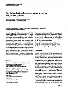
1. Introduction River-fed sediment plumes in estuaries and deltas are important to be monitored, because of their influence on water quality and the environment. The techniques employed to monitor nearshore environments can be classified into two main categories: remotely and in situ methods. For remote sensing, satellite devices (AVHR Radiometer [1], images from MODIS-Aqua [2]) or unmanned aerial vehicles [3] have been used. In situ measurements can be taken by means of underwater sensors (i.e., river drifters [4] or video remote sensing [5]). Underwater Wireless Sensor Networks (UWSNs) are a very promising and convenient instrument in oceanography, in particular for pollution monitoring and offshore exploration [6]. Sediment plumes may show different patterns due to currents and wind. Figure 1 presents a possible deployment of UWSN, intended to cover the area of interest. There are two types of nodes in the network: sensor and sink nodes. Sink nodes collect data from sensor nodes and serve as network gateways. The shallow water acoustic channel is highly hostile. Therefore, the choice of an
efficient MAC protocol is essential to the design of UWSN [7]. Two multihop transmission mechanisms from sensors to sink nodes are possible: broadcast or point-to-point. The latter is the chosen option for the present work. Concerning the choice between channel-partitioning or random access protocols [8, 9], time-division multiplexing (TDM) is the preferred technique, because of its simplicity and power efficiency. To overcome the limited throughput, Spatial TimeDivision Multiple Access (STDMA), which is a collision-free multihop channel access protocol [10], is used in the present work. Since all node locations are equally important in terms of data acquisition, transmission fairness [11] is a scheduling objective. In this analysis, fairness means that all nodes transmit the same amount of their own data in the long-term, regardless of their distance from the sink node. In this paper, a network with a single sink will be analyzed. Two different gateway locations are considered and it will be shown how its location has a strong influence on the network throughput. Previous works by other authors deal with fairness scheduling in STDMA networks. Wang et al.
2
Journal of Sensors
Sea
12
11
B A
N W
8
E S
6
5
Shore 2
13
9
10
3
7
Estuary 1
4
(a)
(b)
Figure 1: (a) Area of interest in an estuary: with West drift (A) or East drift current (B). (b) Proposed topology of a network with one gateway and 12 sensor nodes covering the area of interest (labeled B, in case (a)).
11 𝜆
𝜆
8 2𝜆
6 2𝜆
2
3
7
4𝜆
1
4
4 (a)
2𝜆 2𝜆
𝜆
10
1
𝜆
2𝜆
7
2𝜆 2 𝜆
𝜆
9
13
2𝜆
3
3𝜆 4𝜆
6 2𝜆
10
3𝜆 4𝜆
5
13 𝜆
3𝜆
12 𝜆
𝜆
9 2𝜆
5
11
12
8 (b)
Figure 2: Example of network with twelve sensors: topology and throughput. Gateway node is node 1, in the gray circle, in both cases. Other nodes are clockwise numbered. (a) Gateway on the corner. (b) Gateway in the center.
proposed a scheduling algorithm, but they emphasized adaptive scheduling instead of shortest frame [12]. Concerning UWSNs, Diamant and Lutz proposed STDMA protocol for ad hoc UWSNs where fairness was considered but not uniformly achieved [13]. Chitre et al. demonstrated that the optimal schedule for random networks is periodic and presented a computationally efficient algorithm that finds good schedules [14] while our work presents a new procedure that finds the optimal scheduling when the location of the nodes is known. Xiao et al. also presented an algorithm to find optimal scheduling in TDMA networks, but only for linear (onerow) topology in UWSNs [15]. Our procedure determines the optimal fair scheduling for the case of saturated load condition (i.e., the sensor nodes have always data to transmit) in a network where the topology follows the estuary shape. Analytical expressions for the frame length and numerical results for the throughput are presented as well.
2. Network Description and Scheduling Before analyzing in depth the STDMA network scheduling, some aspects should be considered. In the network topology shown in Figure 1(b) the nodes are located at the vertex of
an equilateral triangular mesh, and they are stationary. Two possible gateway locations are shown in Figure 2: gateway on the corner and in the center. The main reason to consider these two locations is that they are the two limiting cases for performance and cost of the network deployment. If a network with a central gateway is chosen, the maximum throughput is obtained at the expense of a higher cost, due to the larger distance from the gateway to the shore. As the word indicates, a plume has the shape of a large feather; that is, it covers an area longer than wide, as shown in Figure 1(a). To fit this area of interest, the chosen network topology consists of three or six (depending on the gateway position) strings coming together to the gateway. Figure 2 also shows the throughput of every node in a 13-node network (12 sensor nodes and a gateway). Neighbor nodes are in the transmission range from each other, and nonadjacent nodes are not, because of transmission power control [15]. Transmit mode is simplex; that is, a node that is transmitting does not receive simultaneously, and vice versa. After an initial synchronization phase, the forwarding table (shown by the arrows in Figure 2) will be set and will remain static. The amount of data acquired by sensors makes that every node always has a packet ready for transmission
Journal of Sensors (saturated load condition). Time is divided into equally long slots. Long propagation delays of acoustic waves and the associated spatiotemporal uncertainty are taken into account when considering a time slot that includes not only the transmission time but also the propagation time and a guard time. When a node transmits, it does so at a constant binary rate: the channel data rate, 𝑅𝑏 , equal for all nodes. A fair frame is defined as the set of slots needed for all nodes to successfully send one and only one packet of its own data to the gateway. Thus, network operation is periodic, the period being the frame duration. Simultaneous transmissions are allowed, in order to minimize the frame length. This is the benefit of Spatial TDMA [10]. TDMA scheduling is the assignment of slots to nodes in order to find a suitable periodic frame. In TDMA scheduling, two types of assignments are possible: node-oriented [16] and link-oriented [17]. In acoustic networks, when transducers (projectors and hydrophones) are not directional, the node-oriented assignment is recommended. The first step in STDMA scheduling is to determine the compatible nodes, which are those nodes that can transmit simultaneously without causing any intranet interference. There are two possible types of transmission incompatibilities [17]: type 1 occurs when a node transmits while its neighbors in the same string are transmitting too; type 2 occurs when a node simultaneously receives from two, or more, different transmitting nodes. Scheduling will cope with the incompatibilities in the network. The next step for the STDMA scheduling is to find the shortest fair frame. This requires solving an optimization problem under two constraints: (i) only compatible nodes can be planned in the same slot and (ii) the number of transmissions of every node must fulfill a fairness operation in the network.
3. Fair Frame Optimization This section details the proposed algorithm to find the optimal fair frame. Let 𝑁 be the number of sensor nodes (labeled 2, . . . , 𝑁+1; node 1 is the gateway), let 𝜆 0 be the throughput of a single node, and let 𝜆 𝑖 be the aggregated throughput of node 𝑖, that is, the throughput due to the data collected by node 𝑖 plus the data received from upstream nodes and forwarded by node 𝑖. A frame is a particular set of 𝑧 time slots, where every slot may contain simultaneous transmissions of compatible nodes. In order to set a fair behavior in the network, the gateway should have received exactly 𝜆 0 from each node of the network by the end of the frame. This constraint forces a number of transmissions 𝑡𝑖 for every node 𝑖 in the frame, given by set 𝑇 = {𝑡2 , 𝑡3 , . . . , 𝑡𝑁+1 }. For instance, in Figure 2(a), 𝑇 = {4, 4, 4, 3, 3, 3, 2, 2, 2, 1, 1, 1}. The procedure used to find the shortest fair frame consists of two steps: (A) look for all sets of compatible nodes and (B) formulate and solve the combinatorial optimization problem to find the shortest fair frame. A third step, to remove the excess transmissions, is a prudent practice to avoid overloading the nodes which are closer to the gateway.
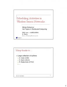
3 3.1. Compatible Nodes. Let 𝐺 = (𝑉, 𝐸) be the network graph, where 𝑉 is the set of nodes. The cardinal of 𝑉 is 𝑁 + 1 (|𝑉| = 𝑁 + 1), and 𝐸 is the set of edges. As shown in Figure 2(a), in our network |𝐸| = 𝑁 and there is a single edge leaving node 𝑛, the so-called edge 𝑒𝑛−1 (because sensor nodes are numbered from 2 to 𝑁 + 1). When a particular node is transmitting, elements 𝑀𝑖𝑗 of the compatibility matrix 𝑀 [10] will be 1 if edges (𝑒𝑖 , 𝑒𝑗 ) can be active simultaneously and 0 otherwise. To enlighten the concept of compatibility matrix an example is provided in Figure 3, where we can note that node 6 has no compatible nodes (𝑀𝑖,5 = 𝑀5,𝑗 = 0), since when node 6 is transmitting, (i) node 3 cannot transmit because it is receiving from node 6, (ii) neighbor node 9 cannot transmit because node 6 is not in the receiving mode, (iii) neighbor nodes 5 and 7 would interfere at node 3, (iv) neighbor nodes 8 and 10 cannot transmit because node 6 transmissions would interfere at nodes 5 and 7, (v) nodes 11, 12, and 13 (label “pn” in Figure 3(a)) cannot transmit because node 6 would interfere at nodes 8, 9, and 10, (vi) Nodes 2 and 4 (label “cn” in Figure 3(a)) cannot transmit because they would interfere at node 3. The network relay scheme can be represented by an oriented graph. The cover of cliques, C = {𝐶1 , 𝐶2 , . . . , 𝐶ℓ }, is the set of maximal cliques in a graph. The natural number ℓ is unknown a priori. Many algorithms are available in the technical literature [18] to find C. Our preferred algorithm is that in [19], due to its efficiency and simple implementation. Every clique 𝐶𝑖 contains an edge or a group of edges that can be active without conflict; obviously, any subset of 𝐶𝑖 also satisfies that requirement. Every edge in the graph is contained in at least one clique of the cover, and every time slot in the frame will contain one clique (or a subset of the clique) of the cover, which ensures the transmission compatibility in that slot. 3.2. Multiple-Vector Bin Packing Problem. We need to find the shortest frame, where each slot contains a set, or a subset, of edges in C, subject to an exact number of instances of every active edge in the frame (to fulfill the requirement of fair operation), which is set 𝑇. This is a Multiple-Vector Bin Packing (MVBP) problem [20], where the bins are the time slots and the items to pack are vectors, which are elements of C or their subsets. This is a combinatorial optimization, which is widely accepted to be NP-complete problem [21]. We
4
Journal of Sensors pn 11
8
5
cn 2
e5
13 pn
9
6 Tx
3
1
12 pn
10
7
4 cn
Gateway
0 0 0 0 0 1 0 1 1 1 1 1
0 0 0 0 0 0 0 0 0 1 1 1
0 0 0 1 0 0 1 1 0 1 1 1
0 0 1 0 0 1 0 0 1 0 1 1
(a)
0 0 0 0 0 0 0 0 0 0 0 0
1 0 0 1 0 0 1 0 0 1 1 0
0 0 1 0 0 1 0 0 1 0 0 1
1 0 1 0 0 0 0 0 0 0 0 0
1 0 0 1 0 0 1 0 0 1 0 0
1 1 1 0 0 1 0 0 1 0 0 1
1 1 1 1 0 1 0 0 0 0 0 0
1 1 1 1 0 0 1 0 0 1 0 0
(b)
Figure 3: Network with 13 nodes and a corner gateway when node 6 is transmitting. (a) Dark gray: neighbor nodes, light gray: parent (pn) and child (cn) of neighbor nodes. (b) Compatibility matrix.
have particularized the general formulation for the present MVBP problem and obtained 𝑛
minimize
∑ 𝑦𝑗
(1)
𝑗=1 𝑛
subject to
∑ 𝑥𝑖𝑗 ≥ 𝑏𝑖 ,
𝑖 = 1, . . . , 𝑚
𝑗=1
(2)
𝑚
∑𝑤𝑖𝑘 𝑥𝑖𝑗 ≤ 𝑦𝑗 𝑊𝑘 , 𝑖=1
𝑗 = 1, . . . , 𝑛, 𝑘 = 1, . . . , 𝑝 (3) 𝑦𝑗 ∈ {0, 1} ,
𝑗 = 1, . . . , 𝑛
(4)
𝑥𝑖𝑗 ∈ {0, 1} , 𝑖 = 1, . . . , 𝑚, 𝑗 = 1, . . . , 𝑛,
(5)
where the output variables are 𝑦𝑗 : 1 if time slot 𝑗 is used or 0 otherwise; 𝑥𝑖𝑗 : number of times that node 𝑖 is assigned to time slot 𝑗 (binary because one node can transmit only once in one slot); 𝑛: length of the shortest frame. The constraint for our frame searching problem is 𝑏𝑖 : demand for 𝑖 node, 𝑏𝑖 = 𝑡𝑖 for a fair frame; 𝑚: number of sensor nodes (𝑁) (𝑚 = 1 is node 2 and so on); 𝑝: total number of 𝐶𝑖 (compatible transmissions: C and subsets); 𝑤𝑖𝑘 : weight of node 𝑖 on the 𝑘th dimension. Each 𝑘vector 𝑤𝑘 = (𝑤𝑖𝑘 )|𝑖=1,...,𝑚 represents clique 𝐶𝑘 ∈ C; 𝑤𝑖𝑘 = 1 if 𝑖 node is an element of 𝐶𝑘 , or 0 otherwise;
𝑊𝑘 : capacity of the 𝑘th dimension. In our case, 𝑊𝑘 will be the number of elements of the largest clique in 𝐶𝐺, 𝑊𝑘 = max({|𝐶1 |, |𝐶2 |, . . . , |𝐶ℓ |}) ∀𝑘. It is important to note that every subset 𝑖 of the clique 𝐶𝑘 is assigned to a different vector 𝑤(𝑘𝑖 ) . For example, in Figure 3, every 𝑤𝑘 will have 𝑁 = 12 components. A maximal clique is 𝐶𝑘 = {3, 12}, and three 𝑤(𝑘𝑖 ) vectors are created: 𝑤(𝑘1 ) = (0, 1, 0, . . . , 0); 𝑤(𝑘2 ) = (0, . . . , 0, 1, 0); 𝑤(𝑘3 ) = (0, 1, 0, . . . , 0, 1, 0), meaning that both node 3 (𝑤(𝑘1 ) ) and node 12 (𝑤(𝑘2 ) ) are allowed to transmit on their own or simultaneously (𝑤(𝑘3 ) ). To find the optimum scheduling of transmissions 𝑥𝑖𝑗 in (1)–(5), an algorithm that solves MVBP problems, based on arc-flow graph formulation [22], is used. 3.3. Excess Transmissions. The constraints in (2) mean that the demand for transmissions (𝑏𝑖 ) may exceed the initial set 𝑇. The workin [22] states that, otherwise, the MVBP solver algorithm may exclude other optimal solutions. In our case, the demand 𝑏𝑖 should fulfill exactly 𝑡𝑖 because of the expected fair behavior of the network. If it is exceeded, two inconveniences arise: (i) a possible traffic bottleneck, because the extra data cannot be delivered to the gateway in a frame and (ii) a waste of energy due to unnecessary transmissions, as the energy consumed by nodes is a critical parameter in UWSNs. The easiest solution is removing the excess of transmissions that exists in the frame.
4. Results For the sake of simplicity, the STDMA protocol has been assumed to be ideal (error-free channel) and the performance of the network has been calculated under these circumstances. In a realistic channel, the packet error rate must be taken into account. Long propagation delays suggest that the preferred error detection and correction technique is FEC (Forward Error Correction). In this case, the throughput is decreased by a factor equal to the redundancy factor of
Journal of Sensors
5 350
Symmetric network (𝑁 mod 6) = 0
Network type
𝐿=𝑁 𝐿 = 7 for 𝑁 = 6 11 𝐿 = ( 𝑁 − 5) for 𝑁 > 6 6
Center Corner
Asymmetric network (𝑁 mod 6) ≠ 0 11 9 𝐿=( 𝑁− ) 6 2
Transmissions/frame
Table 1: Length of the optimal fair frame.
300 250 200 150 100 50 0
60 (27, 45)
40
(21, 34)
30
(15, 23)
(18, 28)
(9, 12)
10 (6, 7) 0 (6, 6) 6
(9, 9) 9
(12, 12) 12
(15, 15)
(18, 18)
15 18 N (sensor nodes)
(21, 21)
(24, 24)
(27, 27) 1
21
24
27
Center Corner
Figure 4: Length of the fair frame in optimal STDMA scheduling.
0.8 0.6 0.4 0.2 0
the FEC overhead, but the optimal fair scheduling remains unchanged. The procedure described in the previous section has been used for networks of different sizes to obtain the shortest fair frame. Frame length 𝐿, shown in Figure 4, cannot be known a priori because the problem is NP-complete. We have analyzed networks with up to 42 nodes and used a polynomial fitting algorithm to find analytical expressions for 𝐿, which are shown in Table 1. These results can help to design a network since they allow calculating a lower bound for the time needed to get a complete data packet from every node. It is remarkable that when the gateway is in the center, the frame length always equals the number of sensors (𝑁). This means that its scheduling has the shortest length. The number of transmissions in a frame, ∑𝑁+1 𝑖=2 𝑡𝑖 , is an important figure concerning energy consumption. It depends only on set 𝑇. When the network has three or six branches and 𝑁 is a multiple of three, the number of transmissions in the optimal fair frame follows a quadratic law in 𝑁, given by 𝑁2 𝑁 = + , ∑ 𝑡𝑖 6 2 𝑖=2 Corner
𝑁+1
2 {𝑁 + { { 12 ={ 2 ∑ 𝑡𝑖 { {𝑁 + 𝑖=2 Center { 12
𝑁+1
12 15 18 21 24 27 30 33 36 39 42 N (sensor nodes)
Figure 5: Total number of transmissions in a fair frame.
(12, 17)
20
9
Center Corner
(24, 39)
Normalized throughput
Slots/frame
50
6
𝑁 , if (𝑁 mod 6) = 0, 2 𝑁 3 + , if (𝑁 mod 6) = 3, 2 4
6
9
12
15 18 21 N (sensor nodes)
24
27
Center Corner
Figure 6: Normalized throughput.
The normalized throughput is defined as the ratio between the binary data rate through the gateway and the channel data rate, 𝑅𝑏 . In the present case, this figure can be calculated as the ratio between the number of sensor nodes and the number of slots in a frame, N/L. Using the length of the optimal fair frame shown in Table 1, the normalized throughput is given in Figure 6. It can be seen that for networks with the gateway in the center the normalized throughput is 1 and that it is possible to get more than 70% of that ideal throughput in networks with up to 12 sensor nodes with the gateway on the corner. We consider that this is a manageable performance loss if we take into account that a gateway close to the shore is more convenient.
5. Conclusion (6)
where “mod” stands for the modulo operation. These results are shown in Figure 5. It is noteworthy that the average number of transmissions per node, ∑𝑁+1 𝑖=2 𝑡𝑖 /𝑁, follows a linear law with 𝑁.
In this paper, a procedure that determines an optimal frame for STDMA UWSN with a fairness requirement has been presented. The network consists of three or six strings coming together to a gateway. The scheduling procedure uses two algorithms, one to find cliques in an oriented graph and MVBP problem solver to find the shortest frame. Analytical expressions for the optimal frame lengths have also been presented. Two gateway locations were considered: at the center/edge of the network. Under ideal conditions, the
6 former has a maximum performance, whereas the latter reaches 70% of the maximum normalized throughput in networks with up to 12 sensor nodes.
Conflict of Interests The authors declare that there is no conflict of interests regarding the publication of this paper.
References [1] A. Marsouin, P. Le Borgne, G. Legendre, S. P´er´e, and H. Roquet, “Six years of OSI-SAF METOP-A AVHRR sea surface temperature,” Remote Sensing of Environment, vol. 159, no. 3, pp. 288–306, 2015. [2] M. J. Devlin, C. Petus, E. da Silva et al., “Water quality and river plume monitoring in the Great Barrier Reef: an overview of methods based on ocean colour satellite data,” Remote Sensing, vol. 7, no. 10, pp. 12909–12941, 2015. [3] V. V. Klemas, “Coastal and environmental remote sensing from unmanned aerial vehicles: an overview,” Journal of Coastal Research, vol. 31, no. 5, pp. 1260–1267, 2015. [4] M. Postacchini, L. R. Centurioni, L. Braasch, M. Brocchini, and D. Vicinanza, “Lagrangian observations of waves and currents from the river drifter,” IEEE Journal of Oceanic Engineering, vol. 41, no. 1, pp. 94–104, 2016. [5] D. Morichon, D. Dailloux, S. Aarninkhof, and S. Abadie, “Using a shore-based video system to hourly monitor storm water plumes (Adour River, Bay of Biscay),” Journal of Coastal Research, vol. 24, no. 4, pp. 133–140, 2008. [6] D. Pompili and T. Melodia, “Research challenges in communication protocol design for underwater sensor networks,” in Underwater Acoustic Sensor Networks, CRC Press, Boca Raton, Fla, USA, 2010. [7] I. F. Akyildiz, D. Pompili, and T. Melodia, “Underwater acoustic sensor networks: research challenges,” Ad Hoc Networks, vol. 3, no. 3, pp. 257–279, 2005. [8] R. Otnes, A. Asterjadhi, P. Casari et al., Underwater Acoustic Networking Techniques, Springer, Heidelberg, Germany, 2012. [9] S. Shahabudeen, M. Chitre, and M. Motani, “Adaptive multimode medium access control for underwater acoustic networks,” IEEE Journal of Oceanic Engineering, vol. 39, no. 3, pp. 500–514, 2014. [10] R. Nelson and L. Kleinrock, “Spatial TDMA: a collisionfree multihop channel access protocol,” IEEE Transactions on Communications, vol. 33, no. 9, pp. 934–944, 1985. [11] J. Mo and J. Walrand, “Fair end-to-end window-based congestion control,” IEEE/ACM Transactions on Networking, vol. 8, no. 5, pp. 556–567, 2000. [12] Z. Wang, F. Yu, J. Tian, and Z. Zhang, “A fairness adaptive TDMA scheduling algorithm for wireless sensor networks with unreliable links,” International Journal of Communication Systems, vol. 27, no. 10, pp. 1535–1552, 2014. [13] R. Diamant and L. Lampe, “Spatial reuse time-division multiple access for broadcast ad hoc underwater acoustic communication networks,” IEEE Journal of Oceanic Engineering, vol. 36, no. 2, pp. 172–185, 2011. [14] M. Chitre, M. Motani, and S. Shahabudeen, “Throughput of networks with large propagation delays,” IEEE Journal of Oceanic Engineering, vol. 37, no. 4, pp. 645–658, 2012.
Journal of Sensors [15] Y. Xiao, M. Peng, J. Gibson, G. G. Xie, D.-Z. Du, and A. V. Vasilakos, “Tight performance bounds of multihop fair access for MAC protocols in wireless sensor networks and underwater sensor networks,” IEEE Transactions on Mobile Computing, vol. 11, no. 10, pp. 1538–1554, 2012. [16] P. Bj¨orklund, P. V¨abrand, and D. Yuan, “A column generation method for spatial TDMA scheduling in ad hoc networks,” Ad Hoc Networks, vol. 2, no. 4, pp. 405–418, 2004. [17] A.-M. Chou and V. O. K. Li, “Slot allocation strategies for TDMA protocols in multihop packet radio networks,” in Proceedings of the the 11th Annual Conference of the IEEE Computer and Communications Societies (IEEE INFOCOM ’92), vol. 2, pp. 710–716, Florence, Italy, May 1992. [18] E. R. Harley, “Comparison of clique-listing algorithms,” in Proceedings of the International Conference on Modeling, Simulation & Visualization Methods and the International Conference on Algorithmic Mathematics & Computer Science (MSV-AMCS ’04), vol. 4, pp. 433–438, Las Vegas, Nev, USA, June 2004. [19] C. Bron and J. Kerbosch, “Algorithm 457: finding all cliques of an undirected graph,” Communications of the ACM, vol. 16, no. 9, pp. 575–577, 1973. [20] B. Patt-Shamir and D. Rawitz, “Vector bin packing with multiple-choice,” Discrete Applied Mathematics, vol. 160, no. 1011, pp. 1591–1600, 2012. [21] M. R. Garey and D. S. Johnson, Computers and Intractability, A Guide to the Theory of NP-Completeness, Freeman, San Francisco, Calif, USA, 1979. [22] F. Brand˜ao and J. P. Pedroso, “Bin packing and related problems: general arc-flow formulation with graph compression,” Tech. Rep. DCC-2013-13, Faculdade de Ciˆencias da Universidade do Porto, Porto, Portugal, 2013, http://www.optimization-online .org/DB FILE/2013/10/4096.pdf.
International Journal of
Rotating Machinery
Engineering Journal of
Hindawi Publishing Corporation http://www.hindawi.com
Volume 2014
The Scientific World Journal Hindawi Publishing Corporation http://www.hindawi.com
Volume 2014
International Journal of
Distributed Sensor Networks
Journal of
Sensors Hindawi Publishing Corporation http://www.hindawi.com
Volume 2014
Hindawi Publishing Corporation http://www.hindawi.com
Volume 2014
Hindawi Publishing Corporation http://www.hindawi.com
Volume 2014
Journal of
Control Science and Engineering
Advances in
Civil Engineering Hindawi Publishing Corporation http://www.hindawi.com
Hindawi Publishing Corporation http://www.hindawi.com
Volume 2014
Volume 2014
Submit your manuscripts at http://www.hindawi.com Journal of
Journal of
Electrical and Computer Engineering
Robotics Hindawi Publishing Corporation http://www.hindawi.com
Hindawi Publishing Corporation http://www.hindawi.com
Volume 2014
Volume 2014
VLSI Design Advances in OptoElectronics
International Journal of
Navigation and Observation Hindawi Publishing Corporation http://www.hindawi.com
Volume 2014
Hindawi Publishing Corporation http://www.hindawi.com
Hindawi Publishing Corporation http://www.hindawi.com
Chemical Engineering Hindawi Publishing Corporation http://www.hindawi.com
Volume 2014
Volume 2014
Active and Passive Electronic Components
Antennas and Propagation Hindawi Publishing Corporation http://www.hindawi.com
Aerospace Engineering
Hindawi Publishing Corporation http://www.hindawi.com
Volume 2014
Hindawi Publishing Corporation http://www.hindawi.com
Volume 2014
Volume 2014
International Journal of
International Journal of
International Journal of
Modelling & Simulation in Engineering
Volume 2014
Hindawi Publishing Corporation http://www.hindawi.com
Volume 2014
Shock and Vibration Hindawi Publishing Corporation http://www.hindawi.com
Volume 2014
Advances in
Acoustics and Vibration Hindawi Publishing Corporation http://www.hindawi.com
Volume 2014