1. Optimisation of Balsa control path using STG resynthesis ... Tangram [9], and Balsa [2], define a high-level programming- ... Figure 1: Balsa design workflow.
1
Optimisation of Balsa control path using STG resynthesis Arseniy Alekseyev, Ivan Poliakov, Victor Khomenko, Alex Yakovlev {arseniy.alekseyev, ivan.poliakov, victor.khomenko, alex.yakovlev}@ncl.ac.uk Newcastle University
Abstract—The paper proposes a modification of the standard design workflow that is used in Balsa design automation system. The controllers obtained by syntax-directed mapping used in Balsa usually suffer from performance, area and power overheads because the predesigned set of components is required to implement the declared protocols fully and correctly in order to be reusable in all possible circuit configurations, which results in redundancy. This redundancy can be eliminated by replacing the manually designed gate-level implementations of the high level components with the corresponding STG specifications. The STGs of individual components that form the system are then composed together to produce the final system STG that is used to synthesise an optimal implementation of the control circuit. The process is automated as a plug-in to Workcraft framework.
I. I NTRODUCTION The main obstacle for the wider spread of asynchronous systems remains to be the inherent complexity of their design. Several solutions are accepted by the industry that ease the design process through abstraction of predesigned asynchronous circuit parts as standardised high level components. A designer is able to use these components as “building blocks”, and then obtain the final gate-level design through an automated mapping process. Furthermore, some of the wellknown asynchronous design automation packages, such as Tangram [9], and Balsa [2], define a high-level programminglike language that is used to describe systems. The language constructs are then directly translated into a network of handshake components – blocks with predefined functionality that use handshakes to interface with other components, which are in turn mapped into a gate netlist. Although this method greatly enhances the designer’s productivity, it has several important drawbacks, of which the control-path overhead is the most decisive. The controllers obtained by syntax-directed mapping are usually far from optimal, because the predesigned components are required to implement their declared protocols fully and correctly in order to be reusable in all possible circuit configurations. However, it is often the case that a significant part of their functionality becomes redundant due to the peculiarities of the specific configuration, e.g. in many cases full handshaking between the components can be avoided. This redundancy can be eliminated by replacing the manually designed gate-level implementation of the high level components with equivalent STG (signal transition graph) [4] specification. The individual component STGs are then composed together to form a complete system STG [5], which
Figure 1: Balsa design workflow is optimised using PETRIFY [1]. An optimal gate-level implementation can then be automatically produced from the STG using tools such as PETRIFY [1], SIS [8] and MPS AT [3]. Automatic synthesis becomes problematic when the size of the STG becomes large: modern synthesis tools can handle STGs with not more than 100 signals. The impact of this problem can be lessened by including STG decomposition tools [7] into the workflow, that would break the large optimised STG down into several smaller STGs that are synthesisable in reasonable time. This paper proposes an automated method to include the aforementioned modification of the standard design workflow that is used in Balsa design automation system [2] using W ORKCRAFT [6] framework. II. BALSA WORKFLOW OPTIMISATION THROUGH STG RESYNTHESIS
The standard Balsa design workflow is comprised of several stages (Figure 1). The designer writes the system specification in Balsa language. It is passed to the Balsa compiler, which generates a handshake component netlist (produced in a language called Breeze) using syntax-directed mapping on the source code. Syntax-directed mapping in this context means that there is a predefined handshake component construct for every syntactic structure. The Breeze netlist is then translated into a gate-level netlist using direct mapping, this time from individual handshake components to their gate-level implementation, which is defined beforehand. The proposed modification of this workflow is shown in Figure 2. The translation from Balsa language into Breeze netlist
2
(a) SequenceOptimised
(b) Concur
Figure 3: Pure control path handshake components and their respective STGs Figure 2: Modified Balsa workflow
is retained (and is still done by the Balsa compiler), but the Breeze-netlist to gate-level-netlist mapping is replaced with the STG resynthesis flow as introduced in section I. Instead of using Balsa tools to produce a gate-level netlist, the Breeze netlist is read by a special interpreted graph model plugin to W ORKCRAFT tool [6], which replaces the handshake components with their STG specifications and produces a composition of those STGs using PC OMP tool. If the resulting STG is small enough, the gate-level implementation may immediately be synthesised using any of the available synthesis tools. However, for many practical cases the composed STG will become quite large. In this case, to synthesise the implementation it is necessary to insert an additional step: STG decomposition. This step is supported by a tool called D ESI J [7]. Therefore, the whole process can be automated using W ORKCRAFT framework. The technique allows to synthesise more efficient control circuits while at the same time preserving the benefit of rapid design methodology fundamental to Balsa. It should be noted, however, that full modelling of all Breeze components with STGs is not practical. The behaviour of most data components would be too complex to synthesise from an STG. Circuit resynthesis for such components would take too much time and would often be less effective than an already existing gate-level implementation done by an experienced designer. Subsequently, all data-related functionality in HCs is modelled outside of STG composition framework: the STG models include only control signals for the data path elements. These control signals are to be connected after the gatelevel generation step to the data-path circuit that is assembled separately (its components are specified by a structural Verilog netlist). The data path is generated automatically side-by-side with the STG behaviour model. III. S UPPORT OF B REEZE H ANDSHAKE C IRCUITS AS I NTERPRETED G RAPH M ODEL IN W ORKCRAFT For the purpose of implementation of the design flow discussed in this paper the Workcraft framework was extended with a plug-in that introduces support for Breeze Handshake Circuits (HCs). The new HC model allows W ORKCRAFT’s
convenient visual editing tools to be applied for creation and editing of Breeze netlists. Import and export of breeze netlists from/to BALSA .breeze files will also be supported, however this feature is not implemented yet. The same plug-in also performs generation of STG behaviour model for the specified HC. The STG generation algorithm is designed to be highly customisable, with support of multiple handshake protocols and various STG implementations for each type of component. Currently, STG generation is implemented for a small set of components and only for one protocol. The library of components will be expanded and will include all Breeze components with support for different handshake protocols. IV. STG SPECIFICATIONS OF INDIVIDUAL HANDSHAKE COMPONENTS
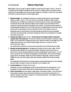
Balsa components can be roughly divided in three groups: pure control components, data path control components and data-control interface components. We will review each group separately. A. Pure control path components Pure control components only control the behaviour of another components and do not carry out any data operations. These components are expected to gain the most from the new design workflow because all of their handshakes are inside the control path and such handshaking does not have to always strictly correspond to the general protocol. Hence, every handshake of such components can potentially be optimised via the STG resynthesis. The examples are Concur (Figure 3b) and SequenceOptimised (Figure 3a) components. The STGs in those figures are highly parallel specifications of these components. However, experimental results show that although such implementation might look better on paper, in practise it is sometimes better to specify traditional, more sequential behaviour. This significantly simplifies the task for synthesis tools, particularly those based on state space exploration techniques, because high parallelism often leads to early state space explosion problem. Besides that, a parallel specification suffers more from CSC (complete state coding) problems: a significant
3
(a) BinaryFunc
(a) While
(b) CallMux (b) Case
Figure 5: Data-control interface components and their respective STGs
C. Data-control interface components
(c) Variable
Figure 4: Pure control path handshake components and their respective STGs
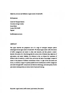
number of auxiliary signals have to be introduced to achieve CSC. B. Data path control components This group of components is used to control the the corresponding data path components that execute predefined operations on data. These operations are far too complex for automated synthesis, but the control path part can still be optimised using STG resynthesis, which makes it reasonable to separate data and control signals. The signals that control the data path are in this case specified as the input and output signals of the component’s STG. Because the data path blocks are outside this specification, their handshake protocols must be implemented strictly and thus cannot be optimised. This, however, does not prevent the optimisation of handshakes that belong to the same component but interface with other control path components. BinaryFunc (Figure 4a), CallMux (Figure 4b), Variable (Figure 4c) are good examples of the data path control components.
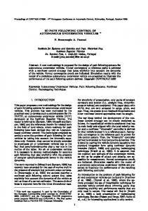
Data-control interface components provide conversion of data to control signals or vice versa. For example, the While component (Figure 5a) analyses the input data to decide whether it should end its operation and conclude the activation handshake, or to continue activating the output handshake. Case component (Figure 5b) handles data in a very similar way, however it has an arbitrary bus width, so for bus widths of more than one bit a decoder that resides in the data path could be used to reduce the STG complexity. These components STGs can become quite complex and the strict behaviour of their data-path handshakes must be preserved. V. A N EXAMPLE : GCD CONTROLLER We have chosen the GCD controller (Figure 6) to demonstrate how the proposed technique applies to real-life circuits. The GCD controller is a good research example because it has components from every group described in section IV and its complexity does not allow omitting of the STG decomposition step, which is an important part of the proposed workflow. All available synthesis tools failed to synthesise a circuit from the fully composed STG model of GCD controller. This proves that the STG decomposition is a necessary step lacking which the synthesis of a practical circuit is not likely to succeed. Decomposition on the level of STG can be replaced with decomposition on the level of handshake components. Such decomposition can be done simply by partitioning the input handshake circuit into blocks, trying to minimise the number of handshakes between blocks, and applying the synthesis process to each block separately. While working with the
4
produced promising preliminary results, however there were still problems during synthesis that prevented the circuit from being completely implemented. Resolutions of these problems is the focus of current work. In the future, STG decomposition tools are going to be integrated into the plug-in to further improve the efficiency. Acknowledgement: this work is supported by EPSRC grant VERDAD EP/G037809/1. R EFERENCES
Figure 6: Breeze Handshake Circuit model of a GCD block
GCD example it was found that decomposition on the level of handshake components can be done much easier and is guaranteed to be successful, whereas decomposition on the STG level is a complex task, which requires additional thirdparty tools. Although the GCD example has not yet been fully synthesised due to issues that arise when the STGs of certain components are connected in specific ways, the results of partial synthesis are quite promising. For comparison, each individual handshake component was synthesised separately and its area estimated. Then, parts of the GCD handshake circuit were synthesised from the STG composition, and the area of this implementation was compared to the sum of areas of individual components implementations. In Figure 6, two such parts are highlighted – one with a dotted line (part 1) and another with a dashed line (part 2). As can be seen from the figure, part 1 is comprised of control path components. This allows to obtain a very significant improvement when the part is synthesised from a large STG: the difference in area is almost 50%. Part 2, however, has a While component in it, which has a data input. Although the width of this input is always fixed at 1 bit, the STG is noticeably worse for synthesis, which results in a less significant improvement of the circuit area: only about 10%. VI. C ONCLUSIONS The methodology presented in this paper aims to improve the existing design workflow of Balsa asynchronous synthesis system. A workflow modification was presented that introduces automated synthesis based on STG composition into the traditional Balsa workflow that allows to lessen the control path overheads. The technique was implemented as a plugin to the W ORKCRAFT framework and the whole process is automatic. A GCD controller was used as a test example that
[1] J. Cortadella, M. Kishinevsky, A. Kondratyev, L. Lavagno, and A. Yakovlev. P ETRIFY: a tool for manipulating concurrent specifications and synthesis of asynchronous controllers. IEICE Trans. Inf. and Syst., E80D(3):315–325, 1997. [2] D. A. Edwards and A. Bardsley. Balsa: An asynchronous hardware synthesis language. The Computer Journal, 45 (1):12–18, jan 2002. [3] V. Khomenko, M. Koutny, and A. Yakovlev. Detecting state encoding conflicts in STG unfoldings using SAT. Fundam. Inf., 62(2):221–241, 2004. [4] Alex Yakovlev. Albert M. Koelmans. Petri nets and Digital Hardware Design Lectures on Petri Nets II: Applications. Advances in Petri Nets, Lecture Notes. Computer Science, 1492:154–236, 1998. [5] Marco A. Pena and Jordi Cortadella. Combining process algebras and petri nets for the specification and synthesis of asynchronous circuits. In ASYNC ’96: Proceedings of the 2nd International Symposium on Advanced Research in Asynchronous Circuits and Systems, page 222, Washington, DC, USA, 1996. IEEE Computer Society. [6] Ivan Poliakov, Victor Khomenko, and Alexandre Yakovlev. Workcraft a framework for interpreted graph models. In Petri Nets, pages 333–342, 2009. [7] Mark Schaefer. Desij - a tool for stg decomposition. Technical Report tr-11-2007, University of Augsburg, October 2007. [8] E.M. Sentovich, K.J. Singh, L. Lavagno, C. Moon, R. Murgai, A. Saldanha, H. Savoj, P.R. Stephan, Robert K. Brayton, and Alberto L. Sangiovanni-Vincentelli. Sis: A system for sequential circuit synthesis. Technical Report UCB/ERL M92/41, EECS Department, University of California, Berkeley, 1992. [9] Kees van Berkel, Joep Kessels, Marly Roncken, Ronald Saeijs, and Frits Schalij. The vlsi-programming language tangram and its translation into handshake circuits. In EURO-DAC ’91: Proceedings of the conference on European design automation, pages 384–389, Los Alamitos, CA, USA, 1991. IEEE Computer Society Press.