CONTINUUM MECHANICS, FLUIDS, HEAT
Optimization of Coordinate Measuring Machine using Steppers SEPTIMIU VALERIAN STANCIU1, IOAN CURTU2, MARIANA DOMNICA STANCIU2, STEFAN DAN1, 1 Automatics Department 2 Department of Strength of Materials and Mechanical Vibrations Transilvania University of Braşov, Adress: B-dul Eroilor nr. 29, Braşov 500036, ROMANIA e-mail:
[email protected],
[email protected],
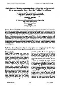
[email protected], SILVIU NASTAC Research Center for Mechanics of Machines and Technological Equipments “Dunarea de Jos” University Adress: Calea Călăraşilor 29, 810017 Braila, ROMANIA Abstract: The CMM computes programming commands from the inspection software with positioning signals from the optical scales sensors and pass to actuators the driving signals in order to reach the prescribed inspection area. The conversion of the command signal into the driving signal can be elaborate by the computer itself, if the driving signal for motors is digital, or by controllers if the actuating signal is analogical (high voltage). A control system that uses steppers as actuators does not require external controllers or D/A conversion and therefore the driving system can be sustained directly by the process computer with a proper integration of the control algorithm into the main inspection software. Such a program sequence to control a step-motor is described in the present paper, the benefits and the weaknesses for a CMM being underlined. Key-Words: Brushless servomotor, Hybrid stepping motor, Closed-loop controller, Software integrated control, Control strategy touch-probe controller), the computer and the machine itself (mechanics and actuators). A sketch of the CMM’s components linked according to the signal flow is given in the figure 1.
1 Introduction Coordinate Measuring Machines inspect manufactured parts to determine the geometrical errors and the shape deviations against the technical drawing or 3D model. The continuous improvement of the production processes and the increase of the customer demands lead to tighten tolerances and strict specifications. As a part of the production plan, the duration of an inspection is very important to meet the delivery time. Therefore in the last years the main CMM’s producers focus their research to reduce the inspection lead time and to acquire more accurate data from the part inspected. Even if the computer uses a fast Ethernet card and the transmission is as fast as it can be, the delay between the computer and the controller and from the controller to actuators is significant, particularly when other applications are running on the computer [9]. The CMM ensemble consists of three controllers (the main controller, probe-head controller and
ISSN: 1790-5095
Figure 1. The CMM ensemble [9]
141
ISBN: 978-960-474-158-8
CONTINUUM MECHANICS, FLUIDS, HEAT
processed signal in order to obtain specific angular displacement. Each quantum of the input conducts to a certain portion of angular displacement, named step. A position is achieved after the rotor pass through all the intermediate transitions and the controller send out the entire drive sequence. The number of impulses prescribes the final location in the working volume of the CMM and the drive frequency is direct proportional with the moving velocity. The figure 2 presents the close loop driving system, with software control instead of a classic controller. The only computer external element that helps to form the command signal is a coordinator before the steppers that acts as a buffer to store the input signal if the driving frequency is higher then the step rate and as a signal splitter for each stepper. Another reason for this element is to limit overcharged currents from the electrical circuit in order to protect the computer ports. In the figure 2 the two blocks (coordinator for sliding on the axes – translation and coordinator for probe head – angular displacement of the touch probe) are pictured separately only for explanatory considerations, in praxis being necessary only one.
Each controller has a precise task and the signals have a long path to cover. The signal transfer time must be added with the processing time in each controller, the conversion of the signals (A/D, D/A) and the response time to evaluate the total amount of one actuation cycle.The operator calls a function and set up the parameters for a measurement in the program; the software is no more then a friendly interface between human and machine, translating the operator intention into command signal. The signal is passed to the main controller where it is split between the actuators and the touch-probe controller. The motors put on move the ram; there are two speed phases: one for moving the probe near the inspected zone and one for touching the surface. Only when the machine is in measure stage (the prehit distance – safety distance between touch-probe and the inspected surface – is achieved) the signal from the main controller is passed to the touch-probe controller. After the deflection the probe is moved back to a prescribe distance (retract) and the arm rests. If the part geometry do not allowed to measure with the normal (A=0, B=0) angle, the operator might choose a different angle from a predefine list and the software pass another command to the probe-head controller. The feedback signals are gathered in the main controller, processed and converted in ASCI code for the computer. The reading signal is given by the touch-probe controller and the optical encoders read the position on the optical rulers and send the data to the main controller.
2 Block-Diagram and the Signal Flow The current paper proposes a solution to shorten the path of the signal to and from the touch-probe elements of the machine. The main idea is to merge the software application with the controller’s routines in a software integrated solution, shortening, in this way, the lead-time from the operator command and the display of the results on the screen. Assuming that steppers are the actuators for this CMM, a software algorithm integrated in the main application can be apply to control directly the loop through incremental encoders, and moreover on the same BUS the computer controls the touch-probe, the probe-head and read the data from the optical rulers. The electrical characteristics and the invariable load on the motor shaft insure the utilization of this type of actuators. From the electrical point of view, stepping motor is incremental mechanism and the input is a digital
ISSN: 1790-5095
Fig. 2. Software integrated closed loop controller [9]
3 Digital Control System To understand the way this control system is working, further details regarding the CMM structure must be brought into discussion and clarified. The purpose of the feedback-loop of the actuators is to maintain a uniform movement (acceleration and deceleration from the initial to the prescribed position), to sustain a constant torque and to avoid faults in synchronization of the motors while pass on the machine axes. The optical encoder’s signals are not accurate enough to
142
ISBN: 978-960-474-158-8
CONTINUUM MECHANICS, FLUIDS, HEAT
a controller from one CMM family to another even if both are produced by the same company (intercompany exchange is out of question) [3], [4]. If the steppers are used, an software algorithm integrated in the main application can be apply to close the loop from the incremental encoders, and moreover on the same BUS the computer controls the touchprobe, the probe-head and read the data from the optical rulers. The electrical characteristics and the invariable load on the motor shaft insure the utilization of this type of actuators without any decrease of accuracy. From the electrical point of view, stepping motor is digital incremental mechanism and the input is a digital processed signal in order to obtain specific angular displacement. Each quantum of the input conducts to a certain portion of angular displacement, named step. A position is achieved after the rotor pass through all the intermediate transitions and the controller send out the entire drive sequence. The number of impulses gives the final location in the working volume of the CMM and the drive frequency is direct proportional with the moving velocity. The coordinator (figure 3) controls the motion of several stepping motors generating for each motor (each axes) two signals: mov and df. The V-low – V-high transition of the mov signal causes the motor to perform a single step in the direction determined by the value of df (df-direction flag set the direction of the movement). The algorithm is based on the digital signals mov and df that form the prescribed location of the CMM – ploc. The digital encoder outputs the actual location of the motor – aloc.
establish the Cartesian coordinates of the touch probe during movement and therefore are neither used to identify the position nor to acquire readings for metrological inspection. Each axis has embedded a precise, glass ruler with interpretable scale lines by a reading sensor. For every translation the computer counts the number of the scale lines passed and at each 10 mm there is a check point on the scale to compare the stored sum with this 10 mm indicator. The optical scales have a null-point, often called reference point and the direction to the end of the scale is the positive direction. If the checksum does not match the 10 mm indicator an error message is displayed and the movement stops. If the movement is successful the current position of the touch probe is stored. The position sensors from the optical scales output a digital signal, easy to be processed by the computer [9]. The probe-head has one motor for each rotation axes (A in vertical plane, B in horizontal plane) and can achieve only discrete positions. Most common probe-heads have a 7.5º step for both axes with a range from 0 to 90º (in some cases 105º) for A-axis and from -180º to +180º for B-axis. The first advantage of using hybrid stepmotors is due to its own discrete movement characteristic and depending on the number of poles even smaller steps can be achieved. The second benefit comes from the permanent magnets that can hold the position even if the phases are not energized. But the most important gain is that all signals are digital therefore no conversion is necessary and command can be passed directly from the computer acquisition card.
4 Hybrid Stepping Motor Facts The coordinate measuring machines use either DC brushless servomotors or hybrid stepping motors as actuators. If DC servomotors application is considered an external closed-loop controller is indispensable due to required D/A conversion of the driving signal for the motor windings. Even if the system structure is complicate and many logical circuits are involved, twenty years before, due to poor development of the digital technology and unreliable stepping motors this architecture was the only robust solution. The technology developed in the meanwhile, but so far the research direction remains the same. Nowadays if a company wants to take advantages of the latest CMM’s technology must scrap the old CMM and acquire the new design that in few years will be also obsolete or for a certain price to upgrade, if possible, the old CMM. The entire system (controller and machine) is built in such a way, that it is almost impossible to exchange
ISSN: 1790-5095
Fig. 3. Close loop controller for one stepper (axis) integrated with the computer [10]
To achieve the prescribe position our controller should evaluate the error between ploc and aloc and
143
ISBN: 978-960-474-158-8
CONTINUUM MECHANICS, FLUIDS, HEAT
pass to the motor’s windings an excitation signal xsig. To maintain a constant torque and to achieve the desired location, the controller evaluates the error term aloc-ploc and as long as the error remains within ±2 steps the excitation signal xsig is independent of the motor position aloc.
intermediary position IP. The distance from AP to IP is covered uniform accelerated and the second half the system decelerate so the final position DP will be achived with no error.
5 The Control Algorithm Under closed-loop conditions the algorithm generates an excitation which is two steps in advance of the motor position and this provides maximum torque at low stepping rates. The control algorithm can be given by [2]: IF | Va | > Vp THEN xu = 3; ELSE xu = 2; ENDIF; IF aloc – ploc < -xu THEN xsig = aloc + xu; ELSEIF aloc – ploc > xu THEN xsig = aloc – xu; ELSE xsig = ploc; ENDIF;
Fig. 4. CMM working volume
This control strategy insure an uniform movement of the CMM ram, without mechanical vibrations induces by a fast break. The decelerate phase have to be travelled as it is shown in the diagram (Fig. 5).
At high stepping rates, however, the current in the stator windings lags behind the excitation signals because of the effect of winding inductance. To obtain the maximum torque under these conditions the excitation should be more than two steps in advance of the motor position. To obtain a good overall performance it is therefore necessary to employ a variable excitation angle, xu which changes from 2 steps to 3 steps as the motor reaches some predetermined rotor speed. To determine when to switch the excitation angle the actual speed (Va) is monitored and compared with a predefined speed (Vp), when the transition must be performed. The stepper control algorithm is referring to regulation of the speed and the torque of the steppers, but the entire positioning system has to process the signal sent by the optical glasses sensors for each the axes: px, py, pz in order to acquire a precise set of coordinates, that will be compared with the CAD model/ technical drawing [8]. In Figure 4 the working volume of a CMM and the reference system recognized by the our controller are presented. The optical glasses are read constantly and the movement is evaluated by the check-sum of the 10 mm checklines. If the the sum does not match an error signal is transmited to the coordinator and the system halt. For a simple AP-DP (AP - actual position, DP desire position ) movement the coordinator calculate the distance and divide by 2 to obtain an
ISSN: 1790-5095
Fig. 5. Speed Diagram
The last interval must be passed at a steady speed (v3). This can be calculated from the data sheet of the motor in order to achieve the desire position (DP) with no inertia error or vibration. A timer and a counter are started for each axis to supervise the movement. The trajectory vector is decompose in its orthogonal components and the signals px, py, pz give the position of the mechanism in the working volume. The counter buffer store the distance travelled and the timer signal switch the speed stage. As long as the probe is within the first half of the entire distance the system is accelerated. When it reaches IP position the speed is kept constant for a period determined
144
ISBN: 978-960-474-158-8
CONTINUUM MECHANICS, FLUIDS, HEAT
In order to achieve the best performance it is necessary to adjust the excitation angle that is used in closed-loop mode according to the motor speed. At low speed an excitation angle of 2 steps is used, increasing to 3 steps at high speeds. By incorporating closed-loop controllers in existing open-loop stepping motor systems the problem of loss of synchronization can be eliminated at relatively low cost. This removes the need to operate at well below the maximum motor torque, and therefore allows a better performance to be obtained.
by the controller. Then the speed is slow down step by step until the final position (DP) [6], [7].
6 Results and Discussion A standard hybrid stepping motor has two stator windings, each of which must be capable of being excited in either sense. In a 4-step sequence both windings are excited at all times and four steps advance the rotor by one tooth. For rotor with 50 teeth, a 4-step sequence gives 200 steps per revolution and a step size of 1.8 degrees. A smaller step size is provided by the 8-step sequence in which eight steps advance the rotor by one tooth. This gives 400 steps per revolution and a step size of 0.9 degrees. The improved resolution obtained at the expense of a slightly reduced torque is not affecting the CMM driving system thanks to the invariant load on the motor shaft. There is a speed barrier to achieve a position in the CMM working volume without errors or vibrations of the ram. That’s why the inspection time can be decreased only by shortcutting the signal path and the processing of the signals. Having 3 or 4 decision structures (computer, main controller, probe-head controller and the touchprobe controller) the signals processing is very slow. The control algorithm together with the architecture described in the first part of this paper offer an alternative solution to the actual CMM constructive types [10]. The problem of loss of synchronization in open-loop stepping motor systems can be overcome by the use of positional feedback. An important application of stepping motors is in mechanical positioning systems where, typically, a single coordinator generates step and dir signals for a number of motors. It is convenient to place the CLC between coordinator and sequencers, with feedback derived from incremental encoders. This simplifies retro-fitting of a CLC to an existing open-loop system [9]. Under normal conditions the stepping motor should behave as if operating open-loop, with the feedback only becoming effective when the error between the nominal and actual motor positions exceeds some limit. The feedback controls the motor excitation in such a way as to generate the maximum torque in the direction of zero positional error. This simple control algorithm leads to a stable system which can recover from loss of synchronization caused by resonance, too-rapid acceleration or excessive load torque. No damping is provided by the control algorithm itself and the closed-loop controller relies on damping in the motor and load for correct operation.
ISSN: 1790-5095
7 Conclusion The most important benefit of the proposed CMM architecture is that the path of the signal is shortening due to the removal of the controllers. The system process only digital signals any conversion being useless and the controller is replaced by a software data processing making any update faster and easier via a patch released by the producer. The delays and the tact difference between the computer and the controller are eliminated, conducting to a substantial time saving. If the software is build on an open sourcing architecture any fault can be faster corrected. In the second part of the paper the control algorithm is presented and the advantages and the disadvantages are discussed. The economical consideration on medium and long term can be estimated, but only the hardware price for the controllers can cover a big portion of the research investment. Adding to this integrated software solution benefits from fuzzy path planning algorithm and image recognition for identification of the position and the geometry of the inspected parts the sketch of a new generation of CMMs is drawn. References: [1] Acarnley, P.P., Gibbons, B.A.: Closed-loop control of stepping motors: prediction and realisation of optimum switching angle, IEEE Proceedings, 1982. [2] Grimbleby J. B.: A Simple Algorithm for ClosedLoop Control of Stepping Motors, IEE Proceedings. - Electr. Power Appl., Vol 142, No 1, pp 5-13., 1995. [3] Hughes A.: Using stepper motors, Proceedings of the first European conference on electrical, University of Leeds, June 1982. [4] Kenjo & Sugawara: Stepping Motors and Their Microprocessor Controls, Oxford Science Publications, New York, 1994. [5] Kuo, B., Cassat, A.: On current detection in variable reluctance step motors, Proceedings of the sixth annual symposium
145
ISBN: 978-960-474-158-8
CONTINUUM MECHANICS, FLUIDS, HEAT
on incremental motion control systems and devices, University of Illinois, 1977. [6] Stanciu V. S., Stanciu Mariana D., Dan St., Curtu I. - Process Optimization Based on Fully Automated CMM, In Proceedings of 7thScientific/Research Symposium with International Participation: Metallic and Nonmetallic Materials MNM2008, Zenica 22-23 May 2008 (Bosnia HerŃegovina), p. 711-716 pe CD, ISBN: 978-9958-785-10-8, in Book of Abstract p. 166. [7] Stanciu V. S., Stefan D., Curtu I. , Stanciu Mariana Domnica -Volumetric Errors Compensation for Coordinate Measuring Machines, In Buletinul Institutului Politehnic din Iasi, Publicat de Univeritatea Tehnica “Gh. Asachi”, Iasi, Tomul LIV (LVIII), Fasc. 1, Sectia Constructii de Masini, 2008, ISSN 1011-2855, p. 73-78. The The papers published in this volume were presented at the 3RD International Conference Advanced Concepts In Mechanical Engineering ACME 2008 Iaşi, Romania June 5 - 6, 2008,
ISSN: 1790-5095
[8] Stanciu V. S., Dan St., Curtu Ioan, Stanciu
Mariana Domnica, Automatic Alignment System for Coordinates Measuring Machines, , in Proceedings of the 19th INTERNATIONAL DAAAM SYMPOSIUM "Intelligent Manufacturing & Automation: Focus on Next Generation of Intelligent Systems and Solutions" - ISI Proceeding, 22-25 Octombrie 2008 Trnava, Slovacia, ISSN 1726-9679, ISBN 978-3901509-68-1, pp. 1299-1300 [9] Stanciu V.S., Dan Stefan ,Stanciu Mariana - An exploratory study for CMM software integrated controller – PART 1, in Proceedings of the 12th International Research/Expert Conference ”Trends in the Development of Machinery and Associated Technology TMT 2008” , 25-30 august 2008, Istanbul-Turcia ISBN 978-9958-61741-6, pp. 749-752. [10] Stanciu V.S., Dan Stefan ,Stanciu Mariana - An exploratory study for CMM software integrated controller – PART 2, in Proceedings of the 12th International Research/Expert Conference ”Trends in the Development of Machinery and Associated Technology TMT 2008” , 25-30 august 2008, Istanbul-Turcia ISBN 978-9958-61741-6, pp. 753-756;
146
ISBN: 978-960-474-158-8