WSEAS TRANSACTIONS on POWER SYSTEMS
M. Mohamed Iqbal, R. Joseph Xavier, J. Kanakaraj
Optimization of droop setting using Genetic Algorithm for Speedtronic Governor controlled Heavy Duty Gas Turbine Power Plants M. Mohamed Iqbal1, R. Joseph Xavier2, J. Kanakaraj3 1,2 - Department of Electrical and Electronics Engineering Sri Ramakrishna Institute of Technology Coimbatore, Tamilnadu INDIA 3 - Department of Electrical and Electronics Engineering PSG College of Technology Coimbatore, Tamilnadu INDIA
[email protected] Abstract: - Biomass is identified as one of the major renewable energy sources for electrical power generation. Heavy duty gas turbine engines are preferred for clean and efficient power generation. An extensive literature survey reveals that the governor droop setting of the heavy duty gas turbines varies from 2 percentage to 10 percentage. But it needs to be optimized for analyzing the dynamic response of heavy duty gas turbine plants in grid connected operation. An attempt has been made in this paper to optimize the speedtronic governor droop setting of all heavy duty gas turbine plants ranging from 18.2MW to 102.6MW using genetic algorithm. Step response of all heavy duty gas turbine plants with the genetic algorithm based droop setting are obtained using MATLAB/Simulink. On comparing the simulation results based on all time domain specifications and performance index criteria, it is witnessed that the genetic algorithm based droop setting yield optimal transient and steady state responses than the previous findings using SYSTAT software. Therefore the genetic algorithm based droop setting is identified as the optimal droop setting for all heavy duty gas turbine plants in grid connected operation.
Key-Words: - Biomass Power, Heavy Duty Gas turbine, Optimal droop setting, Genetic Algorithm, Simple cycle operation, Simplified Model, Single shaft turbine, Speedtronic Governor, SYSTAT connected operation. It is more advantageous because of better energy conversion efficiency and fuel flexibility etc. [3], [4]. HDGT is classified based on the number of shaft used, as single shaft and twin shaft HDGT with the governors respectively speedtronic and woodward governor [5-7]. Rowen has developed the typical transfer function model for analysing the stability response of speedtronic governor based HDGTs ranging from 18.2 MW to 106.7 MW that are useful for simple cycle operation [5]. There are many attempts made to identify the simplified transfer function model of HDGT for simple cycle and combined cycle operation [8-12]. Based on the simulation response of HDGT with speedtronic governor, the droop governor mode is found to be better than the isochronous mode for grid connected operation [13]. Load disturbances in power system may lead to instability and cause for inevitable shut down. Therefore, the power system stability need to be
1 Introduction Energy scenario worldwide had forced the researchers to look for the alternative energy sources such as solar, wind and biomass etc. Biomass becomes the second largest renewable energy source for electrical power generation in India. Installed capacity of the renewable energy sources has reached 12.95 percentage of the available potential as on March 2014 [1]. Cumulative achievement of renewable energy sources on grid connected and off-grid mode of operation in India is identified as about 33,791MW and 1,123MW respectively as on December 2014 [2]. Because of the advancements in Biomass gasification system and huge achievement of grid interactive biomass power in India as about 1,365 MW until December 2014 [2], biomass based gas turbine plants has become the viable option for power generation. Heavy Duty Gas Turbine (HDGT) of General Electric Co., has been used widely for electric power generation in grid
E-ISSN: 2224-350X
117
Volume 11, 2016
WSEAS TRANSACTIONS on POWER SYSTEMS
M. Mohamed Iqbal, R. Joseph Xavier, J. Kanakaraj
ensured by properly designing the controllers for governor and excitation control systems [14-16]. Field survey conducted in Tamilnadu, India, covering 84 Biomass gasifier plants also highlighted the importance of proper design and implementation of the controller for the stable and reliable operation of the plants [17], [18]. An extensive research works are carried out to develop various controllers for the single shaft HDGT plants [19-23]. The literature reveals that the droop setting of the speedtronic governor in single shaft HDGT can vary from 2 percentage to 10 percentage [5]. Researchers had attempted to find the optimal droop setting for 7001Ea Model using SYSTAT software, considering only the settling time of the time domain response [24]. But the droop setting identified by this procedure cannot be the optimal value, since it was optimized by using only the settling time. Therefore the authors had attempted to optimize the droop setting of all HDGT plants by manual tuning [23]. In this paper, it is attempted to optimize the governor droop setting of all the HDGT plants [5], [23], using the well-known optimization technique called Genetic Algorithm (GA). GA is very well known for its capability of arriving at the optimal as well as the global solution by using the concept of natural selection and genetic inheritance [25-27]. The step response of all HDGT models with GA based optimal droop settings are obtained and compared with that of the previous findings using SYSTAT equations. The simulation responses are analysed based on all the time domain responses and performance indices. The comparative results indicate that the droop setting obtained through the GA is more optimal than that obtained using SYSTAT software. The droop setting optimized in this paper also confirms the optimal droop value already obtained by the author using manual tuning. Hence the GA based droop setting is identified as an optimal droop setting for all HDGT plants.
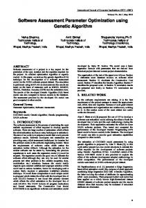
corresponding to the minimum fuel consumption. Simulation response of HDGT with these limiters showed that the performance of acceleration and temperature limiter is diminished under normal operating conditions. Therefore the temperature and acceleration controller are neglected and the simplified transfer function model of HDGT plants is identified [21], [23]. Speed control loop is identified as the main control loop in the simplified HDGT model. Temperature Error Speed Error
Speed Governor
Fuel System dynamics
LVS
Gas turbine dynamics Turbine Torque
Acceleration Limiter Acceleration Error
Fig. 1 – Block diagram of gas turbine with limiters
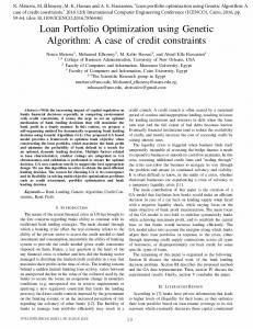
The simplified model with speed control loop consists of speed governor / limiter, fuel system actuator and the valve positioning system as shown in Fig. 2. Speed governor can be operated in either droop or isochronous mode, based on whether the gas engines are used for generator applications or motor control application [5]. The transfer function of the speed governor relating the output control signal, C and the speed error, e, has been represented in Equation (1). The parameter ‘W’ denotes the reciprocal of governor droop setting ‘D’. The prime objective of this paper is to optimize this parameter only. The speed governor has the mode selection parameter denoted by Z that will be equal to 1 for droop governor mode, and 0 for isochronous mode of operation. For self-sustaining under no-load conditions, HDGT models require 23 percent of its rated fuel [5].
2 Simplified Model of Gas Turbine
C(s)
Gas turbine engines are designed based on thermodynamic laws [3]. It consists of compressor, turbine and combustion chamber etc. The transfer function model of HDGT models developed by Rowen in the year 1983, consists of
e(s)
=
W (Xs +1)
(1)
Ys +Z
The fuel system consists of two components namely valve positioner and fuel system actuator whose transfer functions are represented in Equation (2) and (3) respectively.
three control loops viz., speed / load limiter, temperature limiter and acceleration limiter [5], [21], [23] as shown in Fig. 1. The output control
Vp (s)
Wd (s)
Wf 2(s)
signals from these limiters are connected to the low value select (LVS) block, which will select the minimum of the control output signals
E-ISSN: 2224-350X
Temperature Limiter
Vp (s)
118
a
(2)
1
(3)
= bs +c
= Ts +1
Volume 11, 2016
WSEAS TRANSACTIONS on POWER SYSTEMS
Speed Governor
Reference Speed
+
M. Mohamed Iqbal, R. Joseph Xavier, J. Kanakaraj
_
+
𝑊𝑊(𝑋𝑋𝑋𝑋 + 1) (𝑌𝑌𝑌𝑌 + 𝑍𝑍)
0.77
+
Rotor Dynamics
Actual Speed
N
Fuel System
Valve Positioner
0.23
𝑎𝑎 (𝑏𝑏𝑏𝑏 + 𝑐𝑐)
Wd
_
1 𝑇𝑇1𝑠𝑠
Load torque
Vp
Turbine torque
F2
+
1 (𝑇𝑇𝑇𝑇 + 1)
Wf2
Wf2 N
Fig. 2 – Simplified MATLAB/Simulink Model of HDGT plant
with the rotor time constant ‘T1’ of the HDGT models along with D.
The gas turbine fuel system generates the fuel supply signal, Wf2, based on the fuel demand signal, Wd. The values of the model parameters are being presented in [5], [23]. The torque characteristic of the gas turbine is the linear function represented in terms of fuel supply, Wf2 and actual turbine speed, N as given in Equation (4). The rotor dynamics with the rotor time constant, T1 determines the actual speed, N of the gas turbine. F2 = 1.3(Wf2 − 0.23) + 0.5(1 − N)
(4)
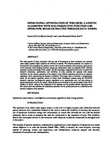
3. Speedtronic Governor Droop Speed governor in the dynamic simulation model acts as the primary controller for maintaining the speed. Based on the simulation response of the simplified HDGT model, droop governor was found to be the better option in the power plant rather than isochronous governor mode [20]. The droop setting of the speedtronic governor varies from 2 percent to 10 percent as per the literature [5]. Since the step response of all HDGT models for various droop settings are almost similar, the response of only 5001M HDGT model is shown in Fig. 3. The simulation results reveal that the steady state error is reduced as the governor droop setting is reduced. As the droop setting is reduced, the peak overshoot is increased and the rise time is decreased. Therefore the governor droop setting needs to be optimized so as to achieve the optimal transient and steady state performance. An attempt had been made to identify the optimal droop setting for only 7001Ea model by considering only the settling time of the time domain response. The settling time expressions that are obtained using SYSTAT software are given in Equations (5) and (6) [24]. Equation (5) deals with the settling time in terms of droop setting ‘D’ in percentage. Equation (6) relates the settling time
E-ISSN: 2224-350X
Fig. 3 – Step response of 5001M Model for various droop settings 𝐒𝐒𝐒𝐒𝐒𝐒𝐒𝐒𝐒𝐒𝐒𝐒𝐒𝐒𝐒𝐒 𝐭𝐭𝐭𝐭𝐭𝐭𝐭𝐭 = 𝟏𝟏𝟏𝟏. 𝟑𝟑𝟑𝟑𝟑𝟑 − 𝟏𝟏. 𝟓𝟓𝟓𝟓𝟓𝟓 𝐃𝐃 + 𝟎𝟎. 𝟏𝟏𝟏𝟏𝟏𝟏 𝐃𝐃𝟐𝟐
(5)
𝐒𝐒𝐒𝐒𝐒𝐒𝐒𝐒𝐒𝐒𝐒𝐒𝐒𝐒𝐒𝐒 𝐭𝐭𝐭𝐭𝐭𝐭𝐭𝐭 = 𝟏𝟏𝟏𝟏. 𝟓𝟓𝟓𝟓𝟓𝟓 − 𝟐𝟐. 𝟑𝟑𝟑𝟑𝟑𝟑 𝐃𝐃 − 𝟎𝟎. 𝟒𝟒𝟒𝟒𝟒𝟒𝟒𝟒 (𝐓𝐓𝐓𝐓) + 𝟎𝟎. 𝟏𝟏𝟏𝟏𝟏𝟏 𝐃𝐃𝟐𝟐 + 𝟎𝟎. 𝟎𝟎𝟎𝟎𝟎𝟎 ∗ (𝐓𝐓𝐓𝐓)𝟐𝟐 + 𝟎𝟎. 𝟎𝟎𝟎𝟎𝟎𝟎 ∗ (𝐓𝐓𝐓𝐓) ∗ 𝐃𝐃 (6)
The droop setting of the HDGT models are being optimized using SYSTAT Equations (5) and (6) and the responses are mentioned respectively as SYSTAT-I and SYSTAT-II in Section-5. The droop setting that are optimized by this procedure may not be the optimized value, unless all the time domain specifications namely maximum peak overshoot, rise time, settling time and steady state error are considered. Therefore it is attempted in this paper, to optimize the governor droop setting of all the HDGT plants, using the well-known and globally accepted optimization technique called Genetic Algorithm (GA). The step response of all HDGT models with GA droop settings are compared with that of SYSTAT equations as shown in Section 5.
4. Genetic Optimization
119
Algorithm
based
Volume 11, 2016
WSEAS TRANSACTIONS on POWER SYSTEMS
M. Mohamed Iqbal, R. Joseph Xavier, J. Kanakaraj
the population by arbitrarily changing one or more elements of the individual.
Genetic algorithm (GA) was invented from the biological evolution model by John Holland in 1960s [25]. It searches for an optimal and global solution to any problem based on the genetic inheritance mechanism of information and the natural selection principle of survival of fittest [26], [27]. GA can be used to obtain the global or approximate optimized solution for any multivariable, non-linear, discontinuous and multiple constraint problems [28]. The optimal solution is obtained by manipulating a population of string that represents various potential solutions. Each string represents the parameter like the chromosomes in natural genes and a group of strings known as population [22]. The algorithmic steps for optimization include the reproduction, crossover and mutation operations as shown in Fig. 4.
The above procedure is repeated until the condition of either the number of generations or the fitness value for the optimization algorithm is reached. Thus the governor droop setting of all the HDGT models are optimized and the simulation responses are compared with that obtained using SYSTAT equations in Section 5.
5. Simulation Results and Discussion Since the simulation response of all HDGT models are almost similar, only 5001M, 7001Ea and 9001Ea models are considered for analysis in this paper. The settling time of these models using SYSTAT equations as mentioned in Section 3 are obtained and shown respectively in Fig. 5, 6 and 7. It shows that the optimal droop setting for the HDGT models is around 7.5 percentage.
Fig. 5 – Settling time of 5001M Model for various droop settings using SYSTAT Equations
Fig. 4 – Flow chart of GA based optimization
GA solves any optimization problem by random searching in large state-space or ndimensional search space. Initially the population is initialized randomly by defining the optimization variables. The fitness value of each chromosome is computed and the better individual is selected through selection process during reproduction stage. After selecting the fitter individual, certain parts of two selected strings are swapped during crossover operation to create the better new individual. During mutation operation, new information is produced in
E-ISSN: 2224-350X
Fig. 6 – Settling time of 7001Ea Model for various droop settings using SYSTAT Equations
120
Volume 11, 2016
WSEAS TRANSACTIONS on POWER SYSTEMS
M. Mohamed Iqbal, R. Joseph Xavier, J. Kanakaraj
Fig. 10 – Step responses of 9001Ea Model with GA and SYSTAT Equations based droop
Fig. 7 – Settling time of 9001Ea Model for various droop settings using SYSTAT Equations
The step response of 5001M, 7001Ea and 9001E models are obtained for a unit step load disturbance applied at 1 second. These models with the droop setting optimized using GA and SYSTAT equations are simulated using MATLAB/Simulink for a period of 10 seconds as explained in Sections 3 and 4 and shown in Fig. 8, 9 and 10 [29]. a
The step response of all the HDGT models are obtained by the same procedure and the time domain specifications namely Maximum peak overshoot (Mp), rise time (Tr), Settling time (Ts) and steady state error (Ess) are obtained and presented in Table 1. Since there is no maximum peak overshoot for SYSTAT-I and II, it is denoted as NA. Since the step responses are obtained with only the primary controller (speed governor), the response is not settled within ± 2% limit. Hence the settling time (Ts) is not mentioned in Table 1.
5001M
5001P
6001B
7001B
Fig. 9 – Step responses of 7001Ea Model with GA and SYSTAT Equations based droop
7001E
7001Ea
9001B
9001Ea
E-ISSN: 2224-350X
121
Optimal Droop
Fig. 8 – Step responses of 5001M Model with GA and SYSTAT Equations based droop
Optimization Technique used
Model code
Table 1 – Time domain specifications of all HDGT Models
SYSTAT-I SYSTAT-II GA SYSTAT-I SYSTAT-II GA SYSTAT-I SYSTAT-II GA SYSTAT-I SYSTAT-II GA SYSTAT-I SYSTAT-II GA SYSTAT-I SYSTAT-II GA SYSTAT-I SYSTAT-II GA SYSTAT-I SYSTAT-II GA
7.49 7.36 2.963 7.49 7.34 2.869 7.49 7.375 3.064 7.49 7.329 2.847 7.49 7.385 3.145 7.49 7.41 3.327 7.49 7.25 2.418 7.49 7.347 2.968
Time domain specifications Mp (p.u.)
Tr (Sec)
Ess (p.u.)
NA NA 0.1873 NA NA 0.1749 NA NA 0.1964 NA NA 0.1599 NA NA 0.2077 NA NA 0.2371 NA NA 0.1254 NA NA 0.1705
2.058 2.0 0.688 2.321 2.233 0.715 1.861 1.813 0.667 2.539 2.429 0.748 1.683 1.651 0.645 1.390 1.366 0.604 4.206 3.93 0.797 2.237 2.161 0.722
0.072 0.071 0.029 0.072 0.071 0.028 0.072 0.071 0.030 0.072 0.071 0.028 0.072 0.071 0.031 0.072 0.071 0.033 0.072 0.07 0.024 0.072 0.071 0.029
Volume 11, 2016
WSEAS TRANSACTIONS on POWER SYSTEMS
M. Mohamed Iqbal, R. Joseph Xavier, J. Kanakaraj
9001Ea
It is identified from the simulation results that he droop setting optimized using GA is found to be around 4 percentage for all HDGT models. This result falls in line with the previous findings by the author using manual tuning [23]. The simulation results also show that the transient as well as steady state responses are improved by using the droop setting obtained using GA than that obtained by SYSTAT equations. Though there is a slight increase in peak overshoot, the rise time (Tr) and steady state error (Ess) of all HDGT models are very much decreased by using the GA based droop setting. Then the performance indices such as Integral of squared Error (ISE), Integral of Time multiplied with squared Error (ITSE), Integral of Absolute Error (IAE) and Integral of Time multiplied with Absolute Error (ITAE) as shown in Equations from (7) to (10) respectively are obtained for all HDGT models and compared as shown in Table 2. QISE
=∫|𝑒𝑒 2 | 𝑑𝑑𝑑𝑑
QITSE =∫|𝒆𝒆
𝟐𝟐 |.
(10)
5001P
6001B
7001B
7001E
7001Ea
9001B
Optimal Droop
5001M
Optimization Technique used
Model code
Table 2 – Performance indices of all HDGT Models
SYSTAT-I SYSTAT-II GA SYSTAT-I SYSTAT-II GA SYSTAT-I SYSTAT-II GA SYSTAT-I SYSTAT-II GA SYSTAT-I SYSTAT-II GA SYSTAT-I SYSTAT-II GA SYSTAT-I SYSTAT-II GA
7.49 7.36 2.963 7.49 7.34 2.869 7.49 7.375 3.064 7.49 7.329 2.847 7.49 7.385 3.145 7.49 7.41 3.327 7.49 7.25 2.418
E-ISSN: 2224-350X
Performance Indices
QISE
QITSE
QIAE
QITAE
0.907 0.895 0.533 0.959 0.944 0.542 0.864 0.854 0.527 0.999 0.981 0.552 0.825 0.817 0.520 0.752 0.746 0.508 1.267 1.231 0.587
0.732 0.710 0.238 0.803 0.774 0.238 0.678 0.660 0.239 0.862 0.828 0.241 0.632 0.617 0.240 0.556 0.546 0.245 1.35 1.266 0.249
1.778 1.75 1.058 1.865 1.831 1.056 1.704 1.68 1.061 1.932 1.894 1.059 1.637 1.616 1.064 1.51 1.495 1.072 2.38 2.31 1.056
4.314 4.222 1.985 4.481 4.368 1.94 4.186 4.108 2.032 4.62 4.493 1.925 4.079 4.011 2.072 3.902 3.855 2.159 5.802 5.538 1.733
0.781 0.754 0.241
1.838 1.806 1.062
4.428 4.322 1.98
Speedtronic governor droop setting of all the HDGT plants are optimized in this paper using GA. The step response of all HDGT plants with the GA based droop setting is compared with that obtained using SYSTAT equations, based on all the time domain specifications and performance index criteria. It is witnessed that the GA based droop setting yield optimal transient and steady state responses than that is optimized using SYSTAT equations. Hence the GA based droop setting is identified as the optimal droop setting for all HDGT models irrespective of the rotor time constants. The optimal droop setting is found to be as 4 percentage, instead of 7.5 percentage as reported by the previous author. GA based droop setting also confirms the optimal droop value obtained by the author using manual tuning. Henceforth the optimal droop setting identified in this paper can be used for developing the controllers and analyze the response of the HDGT plants in grid connected operation.
(9)
QITAE =∫|𝒆𝒆|. 𝒕𝒕 𝒅𝒅𝒅𝒅
0.943 0.928 0.544
6. Conclusion
(8)
QIAE =∫|𝒆𝒆| 𝒅𝒅𝒅𝒅
7.49 7.347 2.968
The simulation results of all HDGT models in terms of the time domain specifications and performance indices show that GA based droop setting yield optimal transient and steady state response. The performance indices are found to be lesser for a GA based droop setting than that found using SYSTAT equations. It proves that the GA based droop setting is the optimal droop setting for all HDGT plants irrespective of the various rotor time constant in grid connected operation.
(7)
𝒕𝒕 𝒅𝒅𝒅𝒅
SYSTAT-I SYSTAT-II GA
References: [1] Energy Alternatives India (EAI), Available online at: http://www.eai.com [2] Ministry of New and Renewable Energy, Government of India. Available online at: http://www.mnre.gov.in [3] Cohen, H., Rogers, G.F.C., and Saravanamutto, H.I.H., Gas turbine theory, 4th Edition, Longman, London, 1996. [4] Giampaolo, T., Gas Turbine Handbook, Principles and Practices, 3rd ed., Lilburn, GA: Fairmont Press/CRC Press, 2006. [5] Rowen,W. I., Simplified mathematical representation of Heavy duty Gas turbines, ASME J. Eng. Power, Vol. 105, No. 4, 1983, pp. 865–869.
122
Volume 11, 2016
WSEAS TRANSACTIONS on POWER SYSTEMS
M. Mohamed Iqbal, R. Joseph Xavier, J. Kanakaraj
using ANN Technique, Elect. Power Compon. Syst., Vol. 29, No.10, 2001, pp.883-896. [16] Mohamed Iqbal, M., Lakshmisankar.S, Hazim Haneef, Variable structured controller for voltage stability enhancement of synchronous generator connected to an infinite bus system, National Power Engineering Conference, 13– 14 March, 2015, pp. 47–52, Madurai, India.
[6] Hannett, L.N., and Khan, A., Combustion turbine dynamic model validation from tests, IEEE Trans. Power Syst., Vol. 8, No. 1, 1993, pp. 152–158. [7] Hannett, L.N., Jee, G., and Fardanesh, B., A Governor / turbine model for a twin-shaft combustion turbine, IEEE Trans. Power Syst., Vol. 10, No. 1, 1995, pp. 133-140. [8] Centeno, P., Egido, I., Domingo, C., Fern´andez, F., Rouco, L., and Gonz´alez, M., Review of gas turbine models for power system stability studies, Ninth Spanish Portuguese Congress on Electrical engineering, 30 June–2 July 2005, pp. 1–6, Marbella.
[17] Mohamed Iqbal, M., Joseph Xavier, R., Arun Kumar, D., Raj Kumar, G., Selva Kumar, P., and Tamilarasan, C., A sample survey on biomass gasifier power plants, International Conference on Emerging Technologies in Renewable Energy (ICETRE-2010), 18–21 August, 2010, Ref. No. P-87, Chennai.
[9] Yee, S. K., Milanovic, J. V., and Hughes, F. M., Overview and comparative analysis of gas turbine models for system stability studies, IEEE Trans. Power Syst., Vol. 23, No. 1, 2008, pp. 108–118. [10] Mohamed Iqbal. M., and Joseph Xavier. R., Ananthi. P., Linearized transfer function model of Biomass based Heavy duty gas turbine plants, International Journal of Applied Engineering Research, Vol. 10, No. 10, 2015, pp. 9637–9642, ISSN 0973-4562.
[18] Mohamed Iqbal, M., and Joseph Xavier,R., Factors influencing the operation of the Biomass gasifier power plants, Second World Renewable Energy Technology Congress and Expo-2011, 21–23 April, 2011, New Delhi. [19] Mohamed Iqbal, M., and Joseph Xavier, R., A review of controllers for isolated and grid connected operation of biomass power plants, International Conference on Renewable Energy Technologies, 16–17 December, 2011, pp. 366– 371, Coimbatore, India.
[11] Shalan, H.E.M.A., Moustafa Hassan, M.A., and Bahgat,A.B.G., Comparative Study on Modelling of Gas Turbines in Combined Cycle Power Plants, International Middle East Power Systems Conference, Paper ID.317, 2010, pp.970-976.
[20] Balamurugan, S., Joseph Xavier, R., and Ebenezer Jeyakumar, A., Simulation of response of gas turbine plant with controllers, Proceedings of National System Conference, 28–29 January, 2007, Ref. No.P105, Manipal.
[12] John Mantzaris and Costas Vournas, Modelling and Stability of a Single-Shaft Combined Cycle Power Plant, Int. Journal of Thermodynamics, Vol.10, No.2, 2007, pp.71-78.
[21] Balamurugan, S., Joseph Xavier, R., and Ebenezer Jeyakumar, A., Control of heavy duty gas turbine plants for parallel operation using soft computing techniques, Elect. Power Compon. Syst., Vol. 37, 2009, pp. 1275–1287.
[13] Balamurugan, S., and Joseph Xavier, R., Selection of governor for heavy duty gas turbine power plant, National Conference on Modern Trends in Electrical and Instrumentation Systems, 9–10 March, 2005, pp. 365–371, Coimbatore, India. [14] Kundur, P., Paserba, J., Ajjarapu, V., Andersson, G., Bose, A., Canizares, C., Hatziargyriou, N., Hill, D., Stankovic, A., Taylor, C., Van Custem, T., and Vittal, V., Definition and classification of power system stability, IEEE Trans. Power Syst., Vol. 19, No. 2, 2004, pp. 1387–1401. [15] Aysen Demiroren, Neslihan S. Sengor, H. Lale Zeynelgil, Automatic Generation Control by
E-ISSN: 2224-350X
[22] Balamurugan,S., Joseph Xavier,R., and Ebenezer Jeyakumar,A., Application of Genetic Algorithm in Optimal PID gain tuning of Heavy Duty Gas Turbine Plant,” Journal of Electrical Systems, Vol. 4, No. 4, 2008, pp.1-10. [23] Mustafa Mohamed Iqbal., Rayappan Joseph Xavier., Fuzzy Self-Tuning PID Controller for Speedtronic Governor Controlled Heavy Duty Gas Turbine Power Plants, Elect. Power Compon. Syst., Vol. 42, No. 14, 2014, pp. 1485-1494. [24] Balamurugan, S., Joseph Xavier, R., and Ebenezer Jeyakumar, A., Selection of governor
123
Volume 11, 2016
WSEAS TRANSACTIONS on POWER SYSTEMS
M. Mohamed Iqbal, R. Joseph Xavier, J. Kanakaraj
and optimization of its droop setting and rotor time constant for heavy-duty gas turbine plants, Indian J. Power Riv. Val. Dev., Vol. 57, 2007, pp. 35–37. [25] Davis.A.L, Handbook of Genetic Algorithm, Van Nostrand Reinhold, 1990. [26] Goldberg.D.E., Genetic Algorithms in Search, Optimization and Machine learning, Addison Wesley Longman, Inc., 1989. [27] Chipperfield, A.J., P.J.Flemming and C.M.Fonscea, Genetic algorithms for control system engineering, Proc. Adapt. Comp. in Engg. Design and Control, 1994, pp. 128-133. [28] Xiangning, Shuohao Ke, Zhengtial Li, Hanli Weng and Xionghuai Han, A fault diagnosis method of Power systems based on Improved Objective function and genetic algorithm-Tabu search, IEEE Transactions on Power Delivery, Vol. 25, No 3, July 2010. [29] MATLAB User Manuals, Mathworks Inc., USA, 2000.
E-ISSN: 2224-350X
124
Volume 11, 2016