790 M. İLARSLAN, S. DEMIREL, H. TORPI, A. K. KESKIN, M. F. ÇAĞLAR, OPTIMIZATION OF FILTER BY USING SUPPORT VECTOR…
Optimization of Filter by using Support Vector Regression Machine with Cuckoo Search Algorithm Mustafa İLARSLAN1, Salih DEMIREL2, Hamid TORPI2, A. Kenan KESKIN2, M. Fatih ÇAĞLAR3 1
Turkish Air Force Academy, 34149, Yeşilyurt, Istanbul, Turkey Dept. of Electronics and Communication Engineering, Yıldız Technical University, Turkey 3 Dept. of Electronics and Communication Engineering, Süleyman Demirel University, Turkey 2
[email protected],
[email protected],
[email protected],
[email protected],
[email protected] Abstract. Herein, a new methodology using a 3D Electromagnetic (EM) simulator-based Support Vector Regression Machine (SVRM) models of base elements is presented for band-pass filter (BPF) design. SVRM models of elements, which are as fast as analytical equations and as accurate as a 3D EM simulator, are employed in a simple and efficient Cuckoo Search Algorithm (CSA) to optimize an ultrawideband (UWB) microstrip BPF. CSA performance is verified by comparing it with other Meta-Heuristics such as Genetic Algorithm (GA) and Particle Swarm Optimization (PSO). As an example of the proposed design methodology, an UWB BPF that operates between the frequencies of 3.1 GHz and 10.6 GHz is designed, fabricated and measured. The simulation and measurement results indicate in conclusion the superior performance of this optimization methodology in terms of improved filter response characteristics like return loss, insertion loss, harmonic suppression and group delay.
Keywords Cuckoo Search Algorithm, optimization, ultrawideband, band-pass filter, Support Vector Regression Machine (SVRM).
1. Introduction In microwave and wireless systems, 3.1-10.6 GHz ultra-wideband (UWB) communication band, which has been dedicated by the Federal Communications Commission (FCC) since February 2002 [1], has a significant role because of its high data-rate, large channel capacity, low power consumption, immunity to multipath interference and coexistence with other wireless systems. With these advantages, UWB communication systems continue to attract attention as a popular research field in both academia and industry. It is incontestable that one of the essential components in UWB RF front-end modules is the band-pass filter (BPF) and hence, BPF design takes a critical role in UWB communication.
Band-pass filters are vital building blocks which allow a signal to pass at requested frequencies and repel the rest of frequencies in receiver and transmission systems. In RF and microwave communication systems, compactness, low insertion loss at the transmission band and high suppression at the rejection band are crucial parameters in order to design a well-suited BPF [2]. Different kinds of UWB BPF design methods and technologies have been investigated for many years in the literature [3-11]. As a filter realization technology, microstrips are thoroughly employed because of their low cost, easy fabrication and integration [12], [13]. Accurate and fast UWB BPF design is a difficult optimization problem as each part of the circuit highly affects the frequency response of the filter to a certain extent. Since there are no analytical models of elements, 3D EM simulators should be used in the design process which thereby consumes a lot of time and CPU resources. In this paper, an accurate and faster methodology for designing a microstrip UWB BPF is demonstrated. This method uses the very popular Support Vector Regression Machine (SVRM) [14-16] which is trained by 3D EM simulator results of the desired microstrip shapes given as the basic design blocks and then combines the blocks to construct the BPF within an efficient and robust optimization process in accordance with the required design objectives. Thus, this method not only avoids the slowness of 3D EM simulators, but is also as accurate as these simulators. Moreover, the easy implementation of different kinds of shapes and technologies like strip lines is one of the prominent features of this novel design methodology. As an application example, an UWB BPF is designed by using three base fundamental shapes; Shunt Stub (SS), Etched Square Stub (ESS) and Defected Ground Structure (DGS). SWRM and Cuckoo Search Algorithm (CSA) are utilized together in the analysis and design of the BPF. In recent years, Cuckoo Search Algorithm has become very popular as a new optimization method amongst the academic communities of various engineering disciplines [17], [18]. It was first proposed by Xin-She Yang and Suash Deb in 2009 and its performance was tested by
RADIOENGINEERING, VOL. 23, NO. 3, SEPTEMBER 2014
791
using standard test functions. The results were superior when compared with other popular meta-heuristic optimization methods like Genetic Algorithm (GA) and Particle Swarm Optimization (PSO). In this study, the training data sets for the desired basis shapes are created first by using the 3D Computer Simulation Technology Microwave Studio (CST MWS) and then the SVRM model of each shape is constructed with these data sets. Then, the output of the obtained SVRM models are fed into the CS optimization algorithm until the BPF design is optimized according to the design goals. The performance of the CSA is compared with the standard Meta-Heuristics; Genetic Algorithm (GA) and Particle Swarm Optimization (PSO) methods. Finally, the designed UWB BPF is fabricated and measured. This paper is composed of 5 sections: After the introduction, the next section states the characteristics and design of the base elements and the SVRM model building. In the third section, the Cuckoo Search Algorithm (CSA) is presented for optimizing the defined cost function by making use of the SVRM models. The design procedure and fabrication of the UWB BPF is given in Section 4 and finally, Section 5 is for the conclusion.
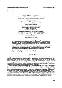
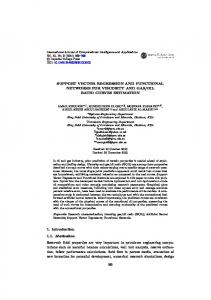
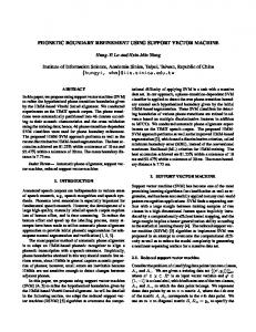
2. Base Elements In this study, 3 kinds of resonator types which are illustrated in Fig. 1-3 are used as the base elements for the UWB BPF design.
rDGS
Wup
up
DGS
WDGS
Fig. 3. Defected Ground Structure with microstrip line base element.
Shunt Stub (SS) behaves like high pass, Etched Square Stub (ESS) works like band stop, while Defected Ground Structure (DGS) shows band stop and low pass characteristics. Operational parameters of the resonators are manipulated by their geometrical dimensions within the limitations of the filter. These limitations could arise from the design objectives such as compactness and the frequency response of the filter. In the design, RO-4350 material which has a dielectric permittivity (εr) of 3.48, substrate thickness (h) of 1.52 mm, copper thickness (t) of 35 μm and a tangent loss (tanδ) of 0.002 is utilized as the substrate.
3. Design Synthesis and Optimization Process 3.1 Mathematical Bases of Support Vector Regression
SS
Given the training dataset ( xi , yi ) , i = 1,2,…, where
yi R and is the size of the training data, Support Vector Regression Machine (SVRM) attempts to construct a continuous mapping function f ( x ) from the independent p-dimensional input variable vector x to the dependent output variable y by linearly combining the results of a nonlinear transformation of the input samples:
WSS
Fig. 1. Shunt stub base element.
up WESS
nsv f ( x ) (i *i ) K ( xi , x ) b
in WESS
up ESS
(1)
i 1
in ESS
ESS WESS Fig. 2. Etched Square stub base element.
where nsv is the number of the Support Vector (SV)s, i 0 , *i 0 are Lagrange multipliers and b is bias parameter, K is a kernel function which performs the nonlinear transformation and in practice, is directly defined. The measure of how well a sample is fitted by the function f is given by a so-called ϵ- insensitive loss function [14] described by
L( f ( xi ) yi ) yi f ( xi ) max 0, yi f ( xi ) (2)
792 M. İLARSLAN, S. DEMIREL, H. TORPI, A. K. KESKIN, M. F. ÇAĞLAR, OPTIMIZATION OF FILTER BY USING SUPPORT VECTOR…
where ϵ is the radius of the regression tube and the distance among the predicted and target values for the training samples is defined as the empirical risk as follows:
R e mp
1
L( x , y , f ) . i 1
i
(3)
i
Therefore, in SV regression, the goal is to minimize Remp. In order to make support vector regression, minimization of the empirical risk formulation (3) is transformed into maximization of equation (4). Using the standard Lagrange multipliers technique, the aforementioned minimization problem can be transformed into Constrained Quadratic Programming (CQP) in which the following function must be maximized with respect to the Lagrange parameters (α, α*) [14]: MaximizeW (,* ) nsv nsv 1 nsv (i* i )( j j* ) K( xi , x j ) (i i* ) yi (i i* ) 2 i , j1 i 1 i 1 (4) subject to:
0 i C , 0 i * C ,
i 1
i
i 1
*
i
(5)
box models of each element are created, including geometrical dimensions of elements as input parameters and S parameters of element as output parameters. Input variable vectors of SS, ESS and DGS models are defined as; up up in in and WDGS , , ESS , WESS , ESS , f WSS , SS , f , WESS , ESS , WESS DGS , Wup , up , r , f , respectively. Output parameters of the
element models are the same; S11 , S11 , S21 , S21 , the magnitude and phase of S parameters. Since the SVRM model has one output, a parallel operation is run to compose the element models. Therefore, each element model contains four machines which have the same input because of the four output parameters. Radial kernel function is exploited for the SVM regression which is described by,
K ( xi , x ) e
Base Element SS
ESS
parameter b can be computed by means of so-called Karush-Kuhn-Tucker conditions [14], [15], [16].
DGS
Lagrangian multipliers ( i , i* ) vanish. The samples
( xi , yi ), i = 1,2,…, nsv that come with non-vanishing coef-
ficients are called Support Vectors (SV). Therefore, we obtain a sparse expansion of the Lagrangian multipliers ( i , i* ) in terms of the input variable vector xi . In other words, we perform generalization between the whole input x - and output y- domains using only a small subset of the training data that ensures enormous computational advantages [14].
3.2 3D EM Simulation-based SVRM Microstrip Modeling In order to obtain accurate and fast design UWB BPF, the SVRM model of basic elements is employed. Black-
2
(6)
where γ is the variance of the kernel function and will be chosen in the training phase. The training dataset of base elements is obtained by CST Microwave Studio within the physical ranges given in Tab. 1.
where index i represents support vector elements of the training data and index j represents irrelevant elements remaining from the training data. The parameter C ˃ 0 measures the trade-off between the capabilities of f ( x ) to approximate the input samples and the error of the new samples. The CQP can be solved using standard optimization techniques subject to the conditions given by (5) and the result in Lagrange multiplier pairs ( i , i* ). The
Since the insensitive loss function given by (2) applies the ϵ- tube selection process to the training dataset ( xi , yi ), i = 1,2,..., , thus only for the samples satisfying f ( xi ) yi , the Lagrangian multipliers ( i , i* ) may be nonzero, and for the samples of f ( xi ) yi , the
xi x
Input Variables WSS (mm) ℓSS (mm) f (GHz) WESS (mm) ℓESS (mm) WupESS (mm) ℓupESS (mm) WinESS (mm) ℓinESS (mm) f (GHz) WDGS (mm) ℓDGS (mm) Wup (mm) ℓup (mm) r (mm) f (GHz)
Min. Value 0.2 3 0.2 0.5 0.5 1.7 1 1 0.5 0.2 0.2 5 1 2 0.2 0.2
Max. Value 1 5 25.2 1 1 2 1.3 1.4 0.7 25.2 0.5 7 2 4 0.5 25.2
Interval 0.2 0.2 1 0.1 0.1 0.1 0.1 0.2 0.1 1 0.1 0.4 0.2 0.2 0.1 1
Data Number 5 11 26 5 5 4 4 3 3 26 4 6 6 11 4 26
Tab. 1. Dimensional range of Base Elements for training data.
Total training data number of neural network for each frequency of SS, ESS and DGS are 55, 3.600 and 6.336, respectively. Furthermore, in Tab. 2, the accuracy of the models, the Support Vector numbers of |S21|, are compared Element
SS
ESS
DGS
|S21| SVs Number
|S11| (%)
0.001 10000 0.05
32
0.001 10000 0.07
23
0.001 10000
|S21| (%)
∟S21 (%)
99.8
99.8 99.9
99.6
99.5
98.1
99.4
99.2
14
98.9
97.2
99.0
98.7
0.001 10000 0.05
1617
99.7
98.8
99.6
98.9
0.001 10000 0.07
1272
99.3
98.6
99.1
98.8
0.001 10000
0.1
820
98.1
97.9
98.3
98.5
0.001 10000 0.05
2915
99.2
98.1
99.0
97.5
0.001 10000 0.07
2002
98.5
97.2
97.9
96.6
0.001 10000
1223
97.2
96.1
96.8
96.0
γ
C
ϵ
0.1
0.1
∟S11 (%)
Tab. 2. Accuracy with respect to SVRM parameters.
RADIOENGINEERING, VOL. 23, NO. 3, SEPTEMBER 2014
for different ϵ insensitive loss parameters. Tab. 2 gives the used SVRM parameters, selection tube radius ϵ, number of the SVs and the resulted accuracy for the SVRM model of the S parameters for 7 GHz. The numbers of SVs used to train the SVRM model for SS, ESS and DGS are 14, 820 and 1223 respectively, with the accuracy of at least 96.0%. The simulation results show that SVRM models of the elements are not only as accurate as the 3D EM simulation model, but also approximately 280 times faster than the CST model
793
GA, there is essentially only one parameter, Pa in CS as the population size (the number of available host nests, n) is fixed, making it very easy to implement and fast to converge.
3.3 Cuckoo Search Algorithm Similar to other meta-heuristic optimization algorithms, it is a bio-inspired optimization algorithm based upon the obligate brood parasitism of some cuckoo species in nature which lay their eggs in the nests of other host birds. The Cuckoo Search which idealizes such breeding behavior was proposed by Xin-She Yang and Suash Deb in 2009 and since then, it has been applied extensively to various engineering optimization problems like antenna array optimization [19], data fusion in wireless sensor networks [20], and to multi-objective design optimization problems like reliable embedded system design [21]. It was also hybridized with quantum computing principles [22] and with power series [23] to obtain better performance. In the CS, each egg in a nest represents a solution, and a cuckoo egg represents a new solution. The aim is to use the new and potentially better solutions (cuckoos) to replace a not-so-good solution (egg) in the nests. In the simplest form, each nest has one egg. The CS is built upon the following three idealized rules: Each cuckoo lays one egg at a time and dumps its egg in a randomly chosen nest; The best nests with high-quality eggs will carry over to the next generation; The number of available host nests, n is fixed, and the egg laid by a cuckoo is discovered by the host bird with a probability Pa (0,1). Discovering means that some set of worst nests (eggs) will be thrown away and their corresponding solutions will be discarded from further calculations. Yang and Deb also discovered that the random-walk style search is better performed by Lévy flights rather than by simple random walk. Many studies have shown that the flight behavior of many animals and insects has demonstrated the typical characteristics of Lévy flights [17-24]. Lévy flight is defined as a random walk with the steplengths based on a heavy-tailed probability distribution which enables CS to explore the whole solution space effectively. An important advantage of CS algorithm is its simplicity. In fact, compared with other population or agent-based meta-heuristic algorithms such as PSO and
Fig. 4. Flow chart of the conventional Cuckoo Search Algorithm.
Fig. 4 is the flow chart indicating the main steps of the regular CS algorithm implementation [24].
3.4 Cost Function Evaluation and Updating Process In microwave circuit design, two port structures could be demonstrated as cascaded connections of sub-structures. Thus, circuits can be solved by using ABCD parameters of each sub-structure. The total ABCD matrix of a circuit which is composed of cascaded n two-ports is described by;
A B A1 C D C 1
B1 A 2 D1 C2
B2 A .......... n D2 Cn
Bn . (7) Dn
In our case, UWB BPF could be considered by connection of each basic element in cascade form. The frequency response of the filter is calculated using (7) and the ABCD parameters of base elements are transformed from S parameters [25] which are obtained by SVRM models per the elements’ dimensions and frequency. There are 2 of SS, 3 of ESS and 4 of DGS in our BPF design making the n = 9. Therefore, the ABCD matrix of the filter is as follows (8-9)
An Cn
T n
Bn D n
(8)
1 2 4 A B 3 9 T SS T DGS T ESS T DGS .............. T SS (9) C D 1 1 1 1 2 Filter
794 M. İLARSLAN, S. DEMIREL, H. TORPI, A. K. KESKIN, M. F. ÇAĞLAR, OPTIMIZATION OF FILTER BY USING SUPPORT VECTOR…
S parameter of the filter is acquired using inverse transformation equations [25]. Meanwhile, there is no need to investigate full S parameters of base elements. The SVRM model results, which give us S11 and S21 of each elements, are enough to calculate ABCD parameters because of the reciprocity S11 = S22 and S12 = S21 [25]. In the design process, the optimal dimensions of the elements for the required UWB filter response are investigated by using the CS algorithm and SVRM models together under the analytical combination of ABCD parameters subject to cost function which is defined as follows (10)
Cost Func. 1. 1 + 2 . 2 + 3. 3 ,
(10)
1
1 S11
,
(11)
2
1 S21
,
(12)
3
1 S11
f1
f 2
(13) f 3
where f1 is picked as 0.2-3.1 GHz to provide suppression at a lower band (11), f2 is selected as 3.1-10.6 GHz to obtain pass band characteristics (12) and f3 is taken between 10.6-20 GHz to suppress the second and third harmonic of the filter (13). Moreover, ω1, ω2, ω3 (10) are chosen as 2/10, 1, 1/10, respectively. Optimization comes to the end when the iteration number is maximized or the cost value is minimized.
4. Design and Comparison of UWB Bandpass Filter In this section, the UWB band pass filter design process is described and then the results of a specific design example are discussed. First, training data sets of bases elements are obtained with a 3D EM simulator in order to form fast and accurate SVRM models of SS, ESS and DGS within their physical limitations. Later, these models are employed in the CSA optimization process in order to obtain the required filter specifications which include rejection and pass band characteristics. The cost function of CSA is determined using analytical calculations of ABCD parameters for cascade-connected base element SVRM models. The CSA optimization process concludes when the iteration number or cost value reaches its limits. If the 3D model of basic elements is utilized instead of fast SVRM models, the duration of the optimization process would be extremely long. The design procedure of the filter is shown in Fig. 5. RO-4350 material as mentioned in Section 2 is used for fabrication of the designed filter circuit. The aim is to design an UWB BPF that has an operational bandwidth between 3.1 GHz and 10.6 GHz. In order to achieve that, the dimensions of base elements of the filter are adjusted using the optimization process. After the optimization, the
Fig. 5. General design procedure for the BPF.
Fig. 6. Scaled filter drawing with grid background. Base Element SS
ESS
DGS
Input Variables WSS (mm) ℓSS (mm) WESS (mm) ℓESS (mm) WupESS (mm) ℓupESS (mm) WinESS (mm) ℓinESS (mm) WDGS (mm) ℓDGS (mm) Wup (mm) ℓup (mm) r (mm)
1. 2. 3. 4. Element Element Element Element 0.6 4 0.6 0.7 2 1.1 1.2 0.6 0.3 5.4 1.6 2.4 0.2
0.8 4.2 0.7 0.6 1.7 1.2 1 0.5 0.4 5.8 1 3.8 0.3
Tab. 3. Solution of the base elements.
0.6 0.7 2 1.1 1.2 0.6 0.3 6.2 1 3.8 0.3
0.2 5 1.6 2.4 0.2
RADIOENGINEERING, VOL. 23, NO. 3, SEPTEMBER 2014
795
20
x 10
-10
Group delay (ns)
15
(a)
10
5
0
-5
(b)
In-Band
0
5
10
15
20
25
F requency (GHz)
Fig. 7. Photographs of the fabricated UWB BPF: (a) top layer, (b) bottom layer.
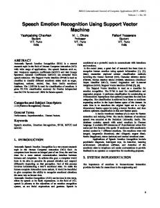
Fig. 9. Measured group delay of the designed UWB BPF.
designed circuit is manufactured and measured. The total size of the filter whose scaled drawing and the actual picture can be seen in Fig. 6 and Fig. 7 respectively is about 2.5 cm × 1.5 cm. The actual dimensions of each base element used in the design are given in Tab. 3. The simulation and actual measurement results are in parallel with each other as given in Fig. 8. It is understood from the results that insertion loss, which increases with frequency, is better than -2 dB over the whole transition band and there is extra loss at the end of the transition band because of the SMA connectors utilized in the ports. Moreover, there is good suppression which is better than 10 dB until 25 GHz which contains the second and third harmonic at the rejection band. Return loss is under -10 dB at pass band. In addition, the low and high cut-off regions of frequency response show that the filter has good sharpness. Furthermore, the designed filter has a flat group delay over the whole operation band, as can be seen in Fig. 9. In the CS optimization process, number of host nest (size of population), and fraction probability (Pa) is chosen as 50 and 0.25, respectively as they provided the best results. 10 0
In order to compare it with other Meta-Heuristics, the PSO optimizer is constructed with the population (particle number) equal to 50, max/min velocity of ±0.1 and learning factors set to 2.0, respectively. Similarly, the GA optimizer has a population (chromosome) of 50, crossover probability of 0.8, and mutation probability of 0.1. The cost results of 30-time tries and 120 iteration of CSA and other standard Meta-Heuristic algorithms and benchmarking at 120th iteration for best try with the corresponding execution times for the same filter are shown in Tab. 4. Algorithm
Worst (max)
Best (min)
Average (mean)
Execution Time (s)
CSA
2.687
0.266
0.813
131
GA
4.999
0.677
2.017
180
PSO
2.158
0.301
1.110
136
Tab. 4. Comparison of the CSA performance with the Standard Meta-Heuristic Algorithms.
A desktop computer with ‘Intel Core i7 CPU, 2.20 GHz Processor, 8 GB RAM’ is used for the design and optimization process. At end of the optimization, the iteration number reaches 65 and the cost value of the operation is equal to 0.266. It is clear from Tab. 4 that CSA has a superior performance with respect to other popular Meta-Heuristics.
S Parameter (dB)
-10
5. Conclusions
-20 -30 -40 |S21 | CST Result -50
|S21 | Measured |S11 | CST Result
-60 -70
|S11 | Measured 0
5
10
15
20
25
Frequency (GHz)
Fig. 8. Simulated and measured S parameters of the designed UWB BPF.
In this paper, a novel design methodology which uses fast and accurate SVRM models of base elements based on a 3D EM simulator is presented to design and analyze an UWB BPF. The outputs of the built SVRM models are used as input by a straightforward, simple and efficient CS algorithm under the rules of circuit theory to solve the filter response. The designed filter is manufactured and measured to show that the actual results are in coincidence with the simulation results. Furthermore, the performance of the CS algorithm is compared with other popular methods like GA and PSO to demonstrate the efficiency of the CS algo-
796 M. İLARSLAN, S. DEMIREL, H. TORPI, A. K. KESKIN, M. F. ÇAĞLAR, OPTIMIZATION OF FILTER BY USING SUPPORT VECTOR…
rithm. The suggested methodology could be used for different kind of element shapes and filter types. Consequently, the proposed design methodology could be considered as an important contribution to the microwave design literature.
References [1] Federal Communications Commission, Revision of Part 15 of the commission's rules regarding ultra wideband transmission system first report and order. Tech. Rep., ET Docket 98-153, FCC02-48, FCC, Feb. 2002. [2] MATTHAEI, G. L., YOUNG, L., JONES, E. M. T. Microwave Filters, Impedance-matching Networks, and Coupling Structures. Norwood: Artech House, 1980. [3] OSKOUEI, H. D., FOROORAGHI, K., HAKKAK, M. Guided and leaky wave characteristics of periodic defected ground structures. Progress In Electromagnetics Research, PIER 73, 2007, p. 15–27. [4] WU, B., LI, B., SU, T., LIANG, C. H. Equivalent-circuit analysis and lowpass filter design of split-ring resonator DGS. Journal of Electromagnetic Waves and Applications, 2006, vol. 20, no. 14, p. 1943–1953. [5] AHN, D., PARK, J. S., KIM, C. S., KIM, J., QIAN, Y., ITOH, T. A design of the low-pass filter using the novel microstrip defected ground structure. IEEE Trans. on Microw. Theory and Tech., Jan. 2001, vol. 49, no. 1, p. 86–93. [6] LEE, J. K., KIM, Y. S. Ultra-wideband bandpass filter with improved upper stopband performance using defected ground structure. IEEE Microw. Wireless Compon. Lett., Jun. 2010, vol. 20, no. 6, p. 316–318. [7] DENG, H. W., ZHAO, Y. J., ZHANG, X. S., ZHANG, L., GAO, S. P. Compact quintuple-mode UWB bandpass filter with good out-of-band rejection. Progress In Electromagnetics Research Letters, 2010, vol. 14, p. 111–117. [8] HUANG, J. Q., CHU, Q. X. Compact UWB band-pass filter utilizing modified composite right/left-handed structure with cross coupling. Progress In Electromagnetics Research, 2010, vol. 107, p. 179–186. [9] CHOU, T. C., TSAI, M. H., CHEN, C. Y. A low insertion loss and high selectivity UWB bandpass filter using composite right/lefthanded material. Progress In Electromagnetics Research C, 2010, vol. 17, p. 163–172. [10] WANG, J. K., ZHAO, Y. J., QIANG, L., SUN, Q. A miniaturized UWB BPF based on novel scrlh transmission line structure. Progress In Electromagnetics Research Letters, 2010, vol. 19, p. 67–73. [11] NAGHSHVARIAN JAHROMI, M., TAYARANI, M. Miniature planar UWB bandpass filters with circular slots in ground. Progress In Electromagnetics Research Letters, 2008, vol. 3, p. 87–93. [12] PARK, J., KIM, J. P., NAM, S. Design of a novel harmonicsuppressed microstrip low-pass filter. IEEE Microw. Wireless Compon. Lett., 2007, vol. 17, p. 424–426. [13] ZHU, Y. Z., XIE, Y. J. Novel microstrip bandpass filters with transmission zeros. Progress In Electromagnetics Research, 2007, vol. 77, p. 29–41. [14] VAPNIK, V. The Nature of Statistical Learning Theory. New York: Springer-Verlag, 1995.
[15] TOKAN, N. T., GÜNEŞ, F. Knowledge-based support vector synthesis of the microstrip lines. Progress In Electromagnetics Research, PIER 92, 2009, p. 65–77. [16] GÜNEŞ, F., TOKAN, N. T., GÜRGEN, F. A knowledge-based support vector synthesis of the transmission lines for use in microwave integrated circuits. Expert Systems with Applications, 2010, vol. 37, p. 3302–3309. [17] YANG, X. S., DEB, S. Cuckoo search via Lévy flights. In Proc. of World Congress on Nature & Biologically Inspired Computing. USA, 2009, p. 210–214. [18] YANG, X. S., DEB, S. Engineering optimisation by cuckoo search. Int. J. Mathematical Modelling and Numerical Optimisation, 2010, vol. 1, no. 4, p. 330–343. [19] KHODIER, M. Optimisation of antenna arrays using the cuckoo search algorithm. IET Microwaves, Antennas & Propagation, 2013, vol. 7, no. 6, p. 458–464. [20] LAYEB, A. Hybrid quantum scatter search algorithm for combinatorial optimization problems. Journal of Annals. Computer Science Series, 2010, vol. 8, no. 2, p. 227–244. [21] KUMAR, A., CHAKARVERTY, S. Design optimization for reliable embedded system using Cuckoo Search. In 3rd International Conference on Electronics Computer Technology. 2011, p. 264–268. [22] LAYEB, A. A novel quantum inspired cuckoo search for Knapsack. International Journal of Bio-Inspired Computation, 2011, vol. 3, no. 5. [23] NOGHREHABADI, A., GHALAMBAZ, M., GHALAMBAZ, M., VOSOUGH, A. A hybrid Power Series – Cuckoo Search Optimization Algorithm to electrostatic deflection of micro fixedfixed actuators. International Journal of Multidisciplinary Sciences and Engineering, July 2011, vol. 2, no. 4, p. 22–26. [24] NAJMY, K., RANI, A., FAREQ, M., MALEK, A., SIEW-CHIN, N. Nature-inspired Cuckoo Search Algorithm for side lobe suppression in a symmetric linear antenna array. Radioengineering, September 2012, vol. 21, no. 3, p. 865–874. [25] GONZALES, G. Microwave Transistor Amplifiers: Analysis and Design. 2nd ed. Prentice Hall, 1996.
About Authors ... Mustafa ILARSLAN was graduated from the Middle East Technical University of Ankara in 1989, with a B.Sc. degree in Electrical & Electronics Engineering. He received M.Sc. degree in Electronics Engineering from the Osmangazi University of Eskisehir, Turkey. He has been the director of Aeronautics and Space Technologies Institute of TurAFA located in Istanbul, Turkey since March 2011. His research interests are aircraft and spacecraft avionics, systems engineering, radar and EW systems and technologies. Salih DEMIREL has received M.Sc. and Ph.D. degrees in Electronics and Communication Engineering from Yıldız Technical University, Istanbul, Turkey in 2006 and 2009, respectively. He has been currently working as an Assistant Professor in the same department. His current research interests are among of microwave circuits especially optimization of microwave circuits, broadband matching circuits, device modeling, computer-aided circuit design, microwave amplifiers.
RADIOENGINEERING, VOL. 23, NO. 3, SEPTEMBER 2014
Hamit TORPI has received M.Sc. and Ph.D. degrees in Electronics and Communication Engineering from Yıldız Technical University, Istanbul, Turkey in 1990 and 1996, respectively. He has been currently working as an Assistant Professor in the same department. His current research interests are in the areas of multivariable network theory, device modeling, computer-aided microwave circuit design, monolithic microwave integrated circuits, and antennas. A. Kenan KESKIN has received M.Sc. degree in Electronics and Communication Engineering from Yıldız Technical University, Istanbul, Turkey in 2012. He has been currently working as a Research Assistant and study-
797
ing as a Ph.D. student in the same department. His current research interests are microwave circuits, computer-aided circuit design, UWB antennas, ground penetrating radars. M. Fatih ÇAGLAR, received his B.Sc. degree in Electronics and Communication Engineering from the Istanbul Technical University in 1996 and M.Sc. degree in Electronics and Communication Engineering from the Suleyman Demirel University, in Isparta, in 1999. He had his Ph.D. degree from the Yıldız Technical University in Istanbul in Communication Engineering in 2007. His current research interests are among of RF/microwave circuits, especially modeling of microwave circuits, computer-aided circuit design and Artificial Neural Networks.