A. Can, A. Ünüvar
Optimizacija parametara obrade u bušenju SMC komposita primjenom Taguchi metode ISSN 1330-3651 (Print), ISSN 1848-6339 (Online) DOI: 10.17559/TV-20160103215256
OPTIMIZATION OF PROCESS PARAMETERS IN DRILLING OF SMC COMPOSITES USING TAGUCHI METHOD Ahmet Can, Ali Ünüvar Original scientific paper This paper has presented and discussed machinability in the drilling of SMC (Sheet Mould Compound) A-Class composite materials using Taguchi's DoE method. The thrust forces, surface roughness and push-out - peel-up delamination behaviour in drilling process for glass fibre reinforced SMC composites have been evaluated. The experimental results and the contribution ratio of parameters on machinability outputs have been statistically analysed by ANOVA. Analysis of variance shows that drill bit angle is the prominent parameter followed by feed rate and cutting speed that contributes towards output responses. Confirmation experiments performed with the optimum parameter condition levels show a reduction in thrust force by 9,8 %, surface roughness by 33,3 %, push-out delamination by 2,5 % and peel-up delamination by 1,38 %. A detailed deformation analysis was investigated for SMC composites. For the empirical modelling of machinability, outputs of SMC composites can be modelled with the quadratic polynomial regression model in a higher range of accuracy. Keywords: SMC (Sheet Mould Compound); drilling; delamination; Taguchi; ANOVA
Optimizacija parametara obrade u bušenju SMC komposita primjenom Taguchi metode Izvorni znamstveni članak U radu se predstavlja i razmatra obradivost kod bušenja SMC kompozitnih materijala A-klase primjenom Tagučijeve Doe metode. Procjenjivale su se potisne sile, površinska hrapavost i raslojavanje listanjem - ljuštenjem SMC kompozita ojačanih staklenim vlaknima u postupku bušenja. Eksperimentalni rezultati i veličina doprinosa parametara na rezultate obrade analizirani su pomoću ANOVA-e. Analiza varijance je pokazala da su važni parametri za izlazne rezultate prije svega kut alata za bušenje te brzina posmaka i brzina rezanja. Potvrdni eksperimenti provedeni uz optimalne parameter pokazuju smanjenje potisne sile od 9,8 %, površinske hrapavosti od 33,3 %, raslojavanja od 2,5 % i raslojavanja listanjem od 1,38 %. Provedena je detaljna analiza deformacije SMC kompozita. Za empirijsko modeliranje obradljivosti, rezultati SMC kompozita mogu se modelirati kvadratnom polinomskom regresijom u viši stupanj točnosti. Ključne riječi: SMC (Sheet Mould Compound); bušenje; raslojavanje; Taguchi; ANOVA
1
Introduction
Polymer matrix composites are important class of materials in advanced structural applications due to their lightweight, high modulus and high specific strength. There is a large application area in automobile, aerospace, aircraft and sport goods industry due to their high modulus, high specific strength and lightweight. Because of high production rate, moulding composites such as sheet moulding compounds (SMC) produced by compression are widely and increasingly applied in different industry branches to produce thin parts such as truck bumper, fender, and windbreaker etc. in automotive industry. Suitable charge flow, temperature distribution in moulds, moulding design and moulding parameter are very important for obtaining a paintable brilliant smooth surface. However mould system looks alike to plastic injection mould, the flow of SMC charge is very hard during mould compression. So the desired gaps like boltrivet holes or headlight-signal holes in a bumper must be ignored in SMC-mould design to obtain a suitable flow. The gaps like holes must be obtained by additional machining operations (drilling-milling) in SMC parts. However, because of their anisotropic, heterogeneous and brittle nature, these materials are difficult to machine [1÷3]. Drilling process is the most frequently used machining operation for composite materials owing to the need to produce holes for subsequent assembly operations of FRP components. Because of the importance, a lot of researches are carried out in the field of machining of composite materials. Researchers reported that the Tehnički vjesnik 24, 2(2017), 435-442
parameters such as tool geometry, tool material, feed rate and cutting speed etc. affect the quality of a drilled hole. As a matter of fact, Faraz et al. pointed out that as many as 55,000 holes are drilled in a single unit production of an Airbus A350 aircraft on FRP composites parts [4]. It is essential to highlight here that due to the actions of machining forces, FRP composites exhibit a number of material damage or machining induced damage, which would not be normally observed during machining of a metallic material. These types of damage include delamination, sub-surface damage, fibre pull out, fibre bridging, spalling, and matrix cracking [5, 6]. Some researchers conducted studies by using unusual special tools for inducing the delamination in machining of composites [7, 8]. Tsao proposed a model with response surface methodology (RSM) based on the Taguchi method. The author evaluated the effect of drilling parameters on delamination by compound core-special drills [9]. In aerospace and automobile parts bolt-rivet joining quality critically depends on the quality of the machined holes. The micro cracks, delamination and fibre pull out near the hole may cause the premature fatigue failure near the bolts and rivets. The quality of drilled holes in failure formation of GFRP directly depends on the appropriate choice of the machining parameters. Machinability is affected greatly by the non-homogenous structure of GFRP composites. Machinability of GFRP is also more complex than the traditional materials such as ferrous and non-ferrous materials. Mechanical and physical properties of matrix material and the fibre reinforcements, fibre types and fibre orientation, volume fraction of fibres have 435
Optimization of process parameters in drilling of SMC composites using Taguchi method
higher influence on the machinability of GFRP composites [10÷14]. The review of previous works about damage free machining was carried out by Kumar. Author pointed out the concentration on tool geometry and materials, surface roughness of drilled surface, thrust force, push and pull out delamination at entry and exit with influence of point angle of drill bit, feed rate, spindle speed and conventional and non-conventional applications [15]. Ramesh et al. [16] worked on the influence of tool materials on thrust force and delamination in drilling of GFRP composites. Three different tool materials (TiN coated and uncoated solid carbide and HSS) were compared in the experiments. Two distinguished delamination mechanisms at the drill entrance (peel up) and exit (push out) were examined with image processing technique. Sunny et al. [17] implemented the experiment by using twist drill, end mill and Kevlar drill to find the optimum drilling parameters using the Taguchi’s method. Author analysed the effect of drill bit material and geometry on delamination. Results of the experiments revealed that reducing feed rate and increasing the spindle speed can reduce the delamination within limits of specified speed and feed rates. Author also reported that feed rate is a more efficient factor on push and pull out delamination than spindle speed, the higher deformation ratio is observed on twist drill and the minimum deformation is observed on Kevlar drill. Davim et al. [18] examined the behaviour of two cemented carbide K10 Drill Bit with different geometry when machining GFRP with Taguchi. The results show that thrust force increased with feed rate; however, lower values were recorded when using the "Brad and Spur" drill. The feed rate has higher effect on the specific cutting pressure and the "Stub Length" drill bit causes higher delamination on the fibre reinforced composites than the "Brad & Spur" tools. Kavad et al. [19] reported a review work about drilling of GFRP and the following conclusions can be drawn: Cutting speed feed rate and tool material are the most influential factors on the delaminating in conventional area. So machining at higher cutting speed, hard tool material and lower feed rate cause lower failure of the GFRP. For reaching low damage levels, high speed machining is suitable for drilling GFRP. High speed machining improves productivity and decreasing production costs. Vibration and Ultrasonic assisted drilling operations cause lower thrust force hence lower failure by comparing to conventional machining. The Ultrasonic and vibration aided machining are more convenient in drilling operation of fibre reinforced composite materials. Hussein et al. [12] studied the influence of milling and drilling parameters on hole machining process. Woven laminated GFRP material is used in experiments. Statistical techniques (ANOVA) were used to determine the effects of the experimental parameters on the surface roughness and hole quality. Hussein reported that milling operations are more appropriate than drilling operations at higher cutting speeds and lower feed rates. When the hole quality (minimum roughness and maximum cylindricity) is important, especially for precision part -assembly operation hole milling may be preferred.
436
A. Can, A. Ünüvar
On the other hand some of the researchers focused on the effect of fibre orientation angle and tool rake angle. It is reported that the fibre orientation has a higher effect on the cutting forces, surface roughness and deformation factor [20]. Vinod and Wanketasvarlu [21] investigated the various effects of geometrical and process parameters on the machining characteristics of Bidirectional GFRP composites with Taguchi and Anova. Authors indicated that the most effective parameter is feed rate which influences the thrust force, followed by cutting speed, chisel edge width and drill bit angle respectively; cutting speed is the most significant factor affecting the drilling torque and the circularity of the hole followed by feed rate, chisel edge width and drill bit angle. Uysal et al. [3] reported an experimental study about tool wear behaviour drilling SMC composite. In this work SMC composite was machined under different cutting speeds, feeds, and drill point angles. The feed and drill bit angle were found to be the most effective factors while cutting speed was the least important parameter on tool wear. Tool wear reduced by increasing feed and decreasing drill bit angle. Most of the previous researchers carried out the experiments with composites manufactured with woven or unidirectional fibre reinforcement directions and with different resins. The works about machining of SMC A-Class composites are very limited. The SMC composites have some differences from conventional GFRP composites such as unsaturated polyester matrix, chopped random fibre orientation and the filler (CaCO3) in the structure. In the present study the drilling experiments were implemented with SMC AClass composite to analyse the effect of drill bit angle and cutting parameters on machinability output such as delamination, thrust forces and surface roughness. 2
Experimental Equipment and Materials
SMC charge containing 30 wt% chopped glass bundle mats (length 25 mm) embedded in a pasty matrix essentially made of CaCO3 (45 wt%) and solvent based unsaturated polyester resin (25 wt%) were used in the experiments. SMC charge sheet is placed on the lower platen of a hot mould (140 °C) before the mould is closed. Then, in a second stage the upper hot mould plate (150 °C) is closed with high press force (1500 tons). After 180 s curing stage the solidified Truck Bumper is removed from mould by ejectors. The experimental plates with size of 130×65×5 mm were derived from the scraps region of bumper derived by machining 5 axis milling robot. The drilling experiments were performed on a MAZAK Variaxis 500-5X five axis machining centre under dry conditions. During the experiments, machinability data such as machining forces, surface roughness and the factor deformation were acquired. The machining forces during machining were measured along the Z-direction (FT – Thrust Force) by 3-axis piezoelectric dynamometer (Kistler®, Model: 9257B) connected to a Kistler® amplifier and a PC with DynoWARE Daq. system. The surface roughness was measured with Mitutoyo® Surftest SJ301. The average roughness, Ra was used to characterize the surface quality. Uncoated tungsten carbide Drill Bit of 6 mm diameter was selected as the cutting tool. The specimen Technical Gazette 24, 2(2017), 435-442
A. Can, A. Ünüvar
Optimizacija parametara obrade u bušenju SMC komposita primjenom Taguchi metode
plates were mounted with a special fixture on the dynamometer. Canon® high resolution scanner was used for determining the macro deformation scale around the hole. A Nikon Stereo microscope (X1000) was used for determining the micro deformation scale as fibre pull out and delamination around the hole. Taguchi method is an immensely popular statistical DOE approach that has been employed in diverse engineering applications [22÷25]. Taguchi DoE Methodology is a very efficient and economical way of experimental design that drastically reduces the number of required experiments. The fundamental principle of Robust Design methods is product improvement through minimization of the effects of various causes of variation. This has been achieved through Taguchi DoE methodology, in which carefully designed trials of different experimental factors and levels have been considered [4]. Three main drilling parameters, Feed Rate (f), Cutting Speed (V) and Drill Bit Angle (K), were selected with three levels. These are the most effective parameters on the Thrust Force (TF), Surface Roughness (Ra) and Factor of Deformation for push out-peel up (FDO-FDU). In the classical full factorial experimentation, (three levels^three factors) 3^3=27 tests
3
No
A
B
C
1 2 3 4 5 6 7 8 9
1 1 1 2 2 2 3 3 3
1 2 3 1 2 3 1 2 3
1 2 3 2 3 1 3 1 2
Vc (m/min) 40 40 40 56 56 56 80 80 80
f (mm/rev) 0,05 0,1 0,2 0,05 0,1 0,2 0,05 0,1 0,2
would be needed. Based on the selected levels and parameters, the tests were performed using the L9 Taguchi OA with nine tests. All the test levels were repeated 3 times and the outputs were averaged. Three levels of three cutting parameters (Cutting Speed, Feed Rate and Point angle) used in the experiments are depicted in Tab. 1. with the results of the experiments, for as a function of the Taguchi-DoE parameters the factor of deformation (FD) can be calculated as the ratio of damaged (delaminated) diameter (Dmax) to hole drilling diameter (D) [8,16,18]. The delaminated diameter around the holes was measured using a high resolution scanner. The scanned images were exported to AutoCAD environment. The damage factor (FD=Dmax/D) was determined after measuring the maximum diameter (Dmax) in the damage zone. The FD value was calculated for both input (FDU-peel up) and output (FDO-push out) surface of the composite materials. As detailed above the experimental results; thrust forces (Ft-N), the Surface Roughness (SR-µm) and the delamination factors (FDUpeel up - FDO-push out) were calculated and analysed using the "lower is the better" signal-to-noise (S/N) ratio.
Table 1 Experimental Results and the Calculated S/N ratio
K (o ) 100 118 140 118 140 100 140 100 118
TF (N) 13,49 13,78 24,90 96,70 113,15 67,27 89,18 36,40 59,47
S/NTF
FDO
S/N FDO
FDU
S/NFDU
−2,60 −22,78 −27,92 −39,70 −41,07 −36,55 −39,00 −31,22 −35,48
1,20 1,16 1,18 1,38 1,43 1,17 1,33 1,26 1,27
−1,44 −1,35 −1,61 −2,83 −3,11 −1,41 −2,49 −1,65 −2,08
1,08 1,13 1,29 1,21 1,23 1,16 1,31 1,19 1,23
−0,72 −1,10 −2,22 −1,68 −1,85 −1,35 −2,38 −1,52 −1,49
Results and discussion
Tab. 2 shows the response table for calculated means and S/N ratios for thrust forces. It is clearly shown that from Tab. 2 the suitable machining parameters for minimum thrust forces are: drill bit angle at Level 1 (K=100°), feed rate (f) at Level 1 (f=0,05) and cutting speed at Level 2 (V=56). It is clear that combination of lower level of drill bit angle and feed rate reduces the thrust forces in drilling of SMC composites. ANOVA was applied to obtain the relative influence of machining parameters on each of the machinability outputs. ANOVA analyses were applied for all S/N ratios of the experimental machinability outputs to predict the optimal parametric combination for obtaining the best machining conditions. Tab. 2 shows the ANOVA analysis for S/N of Thrust Forces (S/NTF). The F-value of the factors, which is higher than the statistical F-Table value; F.05,(2/8)= 4,459, is considered as significant at 95 % confidence level. As it can be seen from the Anova Tab. 2 of S/NTF it is statistically proved that Drill Bit Angle (K) is the major factor (85,4 %) affecting the Thrust Forces. Then the Feed Rate (f) is the second affecting (12,81 %) parameter on the thrust forces. This interaction between the Drill Bit Angle, Feed Rate and Thrust forces is depicted as 3D surface plot in Fig. 1. Tehnički vjesnik 24, 2(2017), 435-442
SR (Ra) 0,21 0,22 0,56 0,33 1,27 1,53 0,54 1,19 0,92
Table 2 Response and Anova Table for S/NTF
Level
K
V
f
S/NSR 13,55 12,95 4,95 9,49 −2,07 −3,72 5,35 −1,51 0,67
Error / Total
1 −24,44* −33,77 −30,13* * 2 −39,11 −31,69 −32,66 3 −35,24 −33,32 −36,00 Delta 14,68 2,08 5,87 Rank 1 3 2 DF 2 2 2 2/8 SeqSS 347,09 7,17 52,09 0,11 / 406,47 MS 173,54 3,58 26,04 0,05 F-Value 3091,67 63,90 464,01 P 0,000 0,01 0,002 % Cont 85,4 1,76 12,81 R^2 = 99,97 % * Optimum parameter level - TF
Tab. 3 shows the response table for the calculated S/N ratios and Anova results for push out delamination (FDO). It can be derived from the values that the greatest influence on the FDO is performed by Drill Bit Angle (K) followed by feed rate as realized like the previous thrust force results. This similarity situation can be explained by the fact that higher feed rates affect thrust force, resulting in serious delamination. There is an interaction between increased thrust forces and increased push out 437
Optimization of process parameters in drilling of SMC composites using Taguchi method
delamination. It is clearly shown in Tab. 3 that the suitable machining parameters for minimum push out delamination are in order to rank; drill bit angle at Level 1 (K=100°), feed rate (f) at Level 1 (f=0,05) and cutting speed at Level 3 (V=80). It is clear that combination of lower level of drill bit angle and lower feed rate reduces the thrust forces and it is reflected on lower push out deformation. This interaction is depicted as 3D surface plot in Fig. 2a. As it can be seen from the Anova Table of S/NFDO it is statistically proved that Drill Bit Angle (K) is the major factor (41,6 %) affecting the push out delamination. Then the Feed Rate (f) is the second effected (36,1 %) parameter on the push out delamination.
A. Can, A. Ünüvar
Tab. 4 shows the response table and Anova results for calculated S/N ratios for peel up delamination S/NFDU. It can be derived from Tab. 4 that feed rate has greater influence on the FDU than (f) Drill Bit Angle (K). Notice that this order is reverse of the order of previous push out delamination. Cutting speed has minor influence on peel up delamination as realized like the push out delamination. It is clear that combination of lower level of feed rate and drill bit angle reduces the push out deformation. This interaction is depicted in Fig. 2b as a surface plot. Table 3 Response and Anova Table for S/NFDO
Level 1 2 3 Delta Rank DF Seq SS MS F-Value P % Cont R^2 = 90,90 %
K V f Error / Total −1,47* −2,30 −1,69* −2,45 −2,18 −2,09 −2,21 −1,65* −2,36 0,979 0,65 0,67 1 3 2 2 2 2 2/8 1,46 0,47 1,26 0,32 / 3,51 0,73 0,23 0,63 0,16 4,57 1,46 3,96 0,18 0,40 0,20 41,6 13,31 36,1 * Optimum parameter level - FDO
As it can be seen from the Anova Table of S/NFDU the Feed Rate (f) is the major factor (63,45 %) affecting the peel-up delamination. Then the Drill Bit Angle (K) is the second affecting (21,78 %) parameter on the push out delamination. The lower feed rate and lower drill bit angles reduces the peel-up delamination.
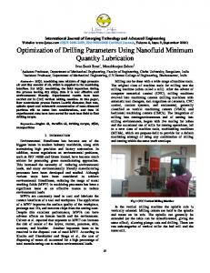
Figure 1 Effects of drill bit angle and feed rate on thrust forces
Table 4 Response and Anova Table for S/NFDU
(a)
Level K V f Error / Total 1 −1,35* −1,56 −1,19* 2 −1,62 −1,49* −1,54 3 −1,91 −1,80 −2,15 Delta 0,56 0,32 0,95 Rank 2 3 1 DF 2 2 2 2/8 Seq SS 0,48 0,15 1,40 0,17 / 2,21 MS 0,24 0,07 0,70 0,08 F-Value 2,82 0,91 8,22 P 0,26 0,52 0,11 % Cont 21,78 7,04 63,45 R^2 = 92,28 % * Optimum parameter level − FDU Table 5 Response Table and Analysis of Variance for S/NRa
(b) Figure 2 Effects of parameters on Push out-Peel Up delamination
438
Level K V f Error / Total 1 10,49* 9,47* 2,77 2 1,23 3,12 7,71* 3 1,50 0,63 2,74 Delta 9,25 8,83 4,96 Rank 1 2 3 DF 2 2 2 2/8 Seq SS 0,84 0,71 0,35 0,01 / 1,93 MS 0,42 0,35 0,18 0,008 F-Value 48,94 41,72 20,79 P 0,02 0,023 0,046 %Cont 43,52 37,1 18,48 R^2 = 99,11 % * Optimum parameter level - Ra
Tab. 5 shows the response table and Anova results for calculated S/N ratios of average surface roughness (Ra). It Technical Gazette 24, 2(2017), 435-442
A. Can, A. Ünüvar
Optimizacija parametara obrade u bušenju SMC komposita primjenom Taguchi metode
can be derived from Tab. 5 that the greatest influence on the surface roughness is exerted by Drill Bit Angle followed by cutting speed and feed rate. It can be explained that the fibre bundles can be machined smoothly by pointed drill. It is clear that the combination of lower level value of drill bit angle and lower level value of cutting speeds reduces the thrust forces and it is reflected in lower fibre push out and lower matrix cracking of machined hole surface which has a significant effect on the surface roughness. Tab. 5, Fig. 3a and Fig. 3b show the suitable machining parameters for minimum surface roughness at Level 1 (K=100°, V=40) and feed rate (f) at Level 2 (f=0,1). As it can be seen from the Anova Table of S/NRa the Drill Bit Angle (K) is the major factor (43,5 %) affecting the surface roughness. Then the cutting speed is the second affecting (37,1 %) parameter on the surface roughness. As expected the higher feeds increase the surface roughness. But, it is derived from response table and figure that the lower feed rates in medium drill bit angles increase the surface roughness surprisingly. It can be explained by the fact that the lower feed rate increases the friction time between the broken hard fibres, fillers (CaCO3) and the machined surface. The friction of powder shaped hard particles may propagate scratches which cause an increase of surface roughness of machined surface. The medium feeds (f≈0,1) are optimal within the lower and medium drill bit angles.
(a)
(b)
(c)
(d) Figure 4 Comparison of experimental outputs with the estimated results
4
(a)
Empirical modelling
Polynomial regression models are developed to analyse the quadratic, cubic and higher-order effects of continuous predictor variables (regresors). The models are developed by using Statistica, statistical software. Correlations have been modelled using Regression Analysis (RA) between machining parameters and the machinability outputs. The general quadratic polynomial regression model can be defined as: Y= β0 + β1 K + β2 K2 +β3 V + β4 V2 + β5 f + β6 f2
(1)
Y is the machinability output, β0 is intercept, β1-6, are coefficients of the empirical model, K is the drill bit angle, V is the cutting speed, and f is the feed rate. Respective intercept and coefficients obtained for TF, FDO, FDU and Ra are as follows: (b) Figure 3 Effects of machining parameter on surface roughness. (a) Drill Bit Angle- Cutting Speed (b) Drill Bit Angle-Feed Rate
Tehnički vjesnik 24, 2(2017), 435-442
TF = −2008,44 + 34 ,47 K + 0 ,14 K 2 − 2 ,16V + 2 (R =0,988) (2) + 0 ,01V 2 + 512 ,92 f − 1073,22 f 2 FDO = −2 ,93 + 0 ,067 K − 0 ,00027 K 2 − (R2=0,909) (3) 2 2 − 0,00103V − 0,00001V + 2,967 f − 8,299 f
439
Optimization of process parameters in drilling of SMC composites using Taguchi method
FDU = 1,0709 + 0,00205K − 0,000001K 2 − (R2=0,926) (4) − 0,0082V + 0 ,000074V 2 + 1,0027 f − 0 ,463 f 2
Ra = −19,69 + 0,295K − 0,0012 K 2 + − 0 ,102V − 0 ,0007V 2 − 22 ,3 f + 84 ,2 f 2
(R2=0,991) (5)
The determination coefficients R2 are higher for TF and Ra equations compared by the FDO and FDU. Eqs. (3) and (6) can be used to determine reliable estimates of thrust forces and surface roughness during drilling of SMC composites. Although the R2 values of FDO and FDU are lower than the TF and Ra, these models can also be used to obtain an acceptable delamination factor. Comparisons of machinability output with the estimated results from regression analysis are presented in Figs. 4a ÷ 4d. As can be seen in the comparison figures the estimated values from Regression Analysis are very close to experimental machinability outputs. 5
Deformation analysis
As mentioned before there are several damage types in machining process of reinforced material. The types of damages are fibre pull-out, delamination, matrix cracking, uncut fibre and matrix, fibre breakage. Two general types, peel up (peel ply) and push out delamination, because the most important damage observed near the holes. In the other hand, for both of them there are two modes of delamination damage, one damage fibre around the hole and the other mode is existing uncut fibre and matrix that can propagate near the hole [21, 26]. In initial observations the deformed regions could not be determined because of the lower contrast in white colour of A-Class SMC material surface. Penetration ink was infiltrated to deformed region for increasing the contrast between the deformed and undeformed region. A sample push-out deformation is depicted in Fig 5a. The microscopic observations show that SMC AClass composites have a resin rich outer layer as depicted in Fig 5b. This is caused by the melted unsaturated polyester resin adhering to the hot steel mould surface while moulding. So, almost never can fibre bundle and filler powder be holding on the hot mould surface and do not exist on this tiny layer. It provides a waterproof, shiny and paintable surface on SMC A-Class composites. A fibre and filler rich zone exists under this layer. A 440
transition zone or an interface exists between the outer resin rich and inner filler-fibre rich zone and it causes a shell cracking-spalling. The resin rich layer can be laminated with no ruptured fibre bundles downward along the drilling direction which causes an uncut matrix-fibre near the hole as depicted in Fig. 5c, 5d and 5e.
(a)
(b)
(c)
(d)
Confirmation experiment
The confirmation experiment is the final step of the Taguchi DoE. Its purpose is to verify that the optimum machining conditions suggested by the matrix experiment do indeed verify the projected improvement for a desired machinability output such as thrust force, delamination and surface roughness. The procedure for S/N ratio calculations from experimental data could be run reversely for determining the predicted value from S/N ratio of optimal levels [9, 17]. The procedure is to backtransform S/N to find expected value and the prediction value. The confirmation experiment with the optimal levels decreased the Thrust force 12,2 N, Push out delamination 1,14, Peel up Delamination 1,09 and surface Roughness 0,14 µm. 6
A. Can, A. Ünüvar
(e) Figure 5 Deformed regions of sample holes
(f)
The penetration ink has exposed the laminated but no ruptured (spalled) shells near the holes. This delaminated but no ruptured regions are depicted in Fig. 5a. The grey colour regions in dashed circles are laminated resin rich shells and exposed by penetration ink. On the other hand, the randomly scraped fibre bundles bounded to uncut matrix are slided-dragged along the downward-drilling direction and it causes a fibre push out delamination as depicted in Fig. 5e. The resin rich shell-layer can be laminated and ruptured with fibre bundles downward along the drilling direction which causes delamination near the holes as depicted in Fig. 5f. 7
Conclusions
The optimization and drilling machinability results for SMC (sheet mould compound) A-Class composites are presented and discussed in this paper. The thrust forces, surface roughness and push out and peel up delamination behaviour in drilling process for glass fibre reinforced SMC composites have been evaluated under different cutting conditions with various bit angles of uncoated cement carbide drill bits. Based on the results the following conclusions can be drawn: In general, the use of proper drill bit angle is the most important in reducing the Thrust force, major defect namely delamination and surface roughness in drilling of SMC composite materials. The drill bit angle has been the first rank for all response tables of machinability output. Technical Gazette 24, 2(2017), 435-442
A. Can, A. Ünüvar
And the optimal level of the drill bit angle has always been Level 1 of parameter factor (K=100°). The optimal level of feed parameter factor has almost been at level 1 (f=0,05) except in surface roughness responses. The suitable cutting speeds for achieving high quality hole on SMC composites are middle range cutting speed (56 m/min) for minimum thrust forces and peel-up delamination, higher range cutting speed (80 m/min) for minimum push-out delamination and lower range (40 m/min) for a minimum surface roughness. Confirmation experiments performed with the optimum parameter condition levels show a reduction in thrust force by 9,8 %, surface roughness by 33,3 %, pushout delamination by 2,5 % and peel-up delamination by 1,38 %. For the empirical modelling of machinability outputs of SMC composites can be modelled with the quadratic polynomial regression model in a higher range of accuracy. In deformation analyses: the randomly scrapped glass fibre bundles can be observed near the hole in-out surface as a no ruptured shape with matrix. And these fibre bundles increase and facilitate the delamination near the hole. The resin rich shell on the SMC surface can be laminated (spalling) near the hole. Acknowledgements This work was supported by Necmettin Erbakan University and Selcuk University Scientific Research Projects (BAP) Coordinators hips. 8
References
[1] Kumar, A.; Saurav, D.; Siba, S. M. Optimization of Thrust, Torque, Entry, and Exist Delamination Factor during Drilling of CFRP Composites. // International Journal of Advanced Manufacturing Technology. 76, (2015), pp. 401416. DOI: 10.1007/s00170-014-6199-3 [2] Dumont, P.; Orge’as L.; Favier, D.; Pizette, P.; Venet, C. Compression moulding of SMC: In Situ Experiments, Modelling and Simulation. // Composites: Part A. 38, (2007), pp. 353-368. DOI: 10.1016/j.compositesa.2006.03.010 [3] Uysal, A.; Altan, M.; Altan, E. Effects of cutting parameters on tool wear in drilling of polymer composite by Taguchi method. // International Journal of Advanced Manufacturing Technology. 58, (2012), pp. 915-921. DOI: 10.1007/s00170-011-3464-6 [4] Faraz, A.; Dirk, B.; Klaus, W. Cutting edge rounding: An innovative tool wear criterion in drilling CFRP composite laminates. // International Journal of Machine Tools & Manufacture. 49, (2009), pp. 1185-1196. DOI: 10.1016/j.ijmachtools.2009.08.002 [5] Tsao, C. C. Thrust force and delamination of core-saw drill during drilling of carbon fiber reinforced plastics (CFRP). // International Journal of Advanced Manufacturing Technology. 37, (2008), pp. 23-28. DOI: 10.1007/s00170-0070963-6 [6] Tsao, C. C.; Chiu, Y. C. Evaluation of drilling parameters on thrust force in drilling carbon fiber reinforced plastic (CFRP) composite laminates using compound core-special drills. // International Journal of Machine Tools & Manufacture. 51, 9(2011), pp. 740-744. DOI: 10.1016/j.ijmachtools.2011.05.004 [7] Tsao, C. C.; Huang, C. C. Analysis of thrust-induced drilling in composite materials using a hemispherical drill.
Tehnički vjesnik 24, 2(2017), 435-442
Optimizacija parametara obrade u bušenju SMC komposita primjenom Taguchi metode
// Int. J. Advanced Manufacturing Technology. 80, (2015), pp. 607-613. DOI: 10.1007/s00170-015-7044-z [8] Tsao, C. C.; Kuo, K. L.; Hsu, I. C. Evaluation of a novel approach to a delamination factor after drilling composite laminates using a core–saw drill. // International Journal of Advanced Manufacturing Technology. 59, (2012), pp. 617622. DOI: 10.1007/s00170-011-3532-y [9] Tsao, C. C. Evaluation of the drilling-induced delamination of compound core-special drills using response surface methodology based on the Taguchi method. // International Journal of Advanced Manufacturing Technology. 62, (2012), pp. 241-247. DOI: 10.1007/s00170-011-3785-5 [10] Azmi, A. I.; Lin, R. J. T.; Bhattacharyya, D. Machinability study of glass fibre-reinforced polymer composites during end milling. // International Journal of Advanced Manufacturing Technology. 64, (2013), pp. 247-261. DOI: 10.1007/s00170-012-4006-6 [11] Azmi, A. I.; Lin, R. J. T.; Bhattacharyya, D. Tool wear prediction models during end milling of glass fibrereinforced polymer composites. // International Journal of Advanced Manufacturing Technology. 67, (2013), pp. 701718. DOI: 10.1007/s00170-012-4516-2 [12] Hussein, M. A.; Asif, I.; Liang, L. A comparative study on the use of drilling and milling processes in hole making of GFRP composite. // Sadhana-Indian Academy of Sciences. 38, (2013), pp. 743-760. [13] Rajamurugan, T. V.; Shanmugam, K.; Palanikumar, K. Analysis of delamination in drilling glass fiber reinforced polyester composites. // Materials and Design. 45, (2013), pp. 80-87. DOI: 10.1016/j.matdes.2012.08.047 [14] Planikumar, K. Experimental investigation and optimisation in drilling of GFRP composites. // Measurement. 44, (2011), pp. 2138-2148. DOI: 10.1016/j.measurement.2011.07.023 [15] Kumar, D.; Singh, K. K. An Approach Towards Damage Free Machining Of CFRP And GFRP Composite Material: A Review. // Advanced Composite Materials. 24, (2015), pp. 49-63. DOI: 10.1080/09243046.2014.928966 [16] Ramesh, M.; Planikumar, K.; Hemachandra, R.K. Influence of Tool Materials on Thrust Force and Delamination in Drilling Sisal-Glass Fiber Reinforced Polimer (S-GFRP) Composites. // Procedia Materials Science. 5, (2014), pp. 1915-1921. DOI: 10.1016/j.mspro.2014.07.513 [17] Sunny, T.; Babu J.; Philip, J. P. Experimental Studies on Effect of Process Parameters on Delamination in Drilling GFRP Composites using Taguchi Method. // Procedia Materials Science. 6, (2014), pp. 1131-1142. DOI: 10.1016/j.mspro.2014.07.185 [18] Davim, J. P.; Pedro, R.; Antonio, C. C. Experimental Study of Drilling Glass Fiber Reinforced Plastics (GFRP) Manufactured By Hand Lay-Up. // Composites Science and Technology. 64, (2004), pp. 289-297. DOI: 10.1016/S02663538(03)00253-7 [19] Kavad, B. V.; Pandey, A. B.; Tadavi, M. V.; Jakharia, H. C. A Review Paper on Effects of Drilling on Glass Fiber Reinforced Plastic. // Procedia Technology. 14, (2014), pp. 457-464. DOI: 10.1016/j.protcy.2014.08.058 [20] Bhanacar, N.; Ramakrishnann, N.; Naik, K.; Komanduri, R. On The Machining of Fiber Reinforced Plastic (FRP) Composite Laminates. // International Journal of Machine Tools & Manufacture. 35, 5(1995), pp. 701-716. DOI: 10.1016/0890-6955(95)93039-9 [21] Vinod, K.V.; Venkateswarlu, G. Optimization of Process Parameters in Drilling of GFRP Composite Using Taguchi Method. // Journal of Material Research Technology. 3, 1(2014), pp. 35-41. DOI: 10.1016/j.jmrt.2013.10.007 [22] Cicek, A.; Kivak, T.; Samtas, G. Application of Taguchi Method for Surface Roughness and Roundness Error in Drilling of AISI 316 Stainless Steel. // Strojniski vestnik-
441
Optimization of process parameters in drilling of SMC composites using Taguchi method
A. Can, A. Ünüvar
Journal of Mechanical Engineering. 58, 3(2012), pp. 165174. DOI: 10.5545/sv-jme.2011.167 [23] Vijay Sekar, K. S., Pradeep Kumar M. Optimising Flow Stress Input for Machining Simulations Using Taguchi Methodology. // Int. Journal of Simulation Modelling. 11, 1(2012), pp. 17-28. DOI: 10.2507/IJSIMM11(1)2.195 [24] Sekulic, M.; Kovac, P.; Gostimirovic, M.; Kramar, D. Optimization of high-pressure jet assisted turning process by Taguchi method. // Advances in Production Engineering & Management. 8, 1(2013), pp. 5-12. [25] Lakshminarayanan, V. R.; Karthikeyan, P.; Aswin, C.; Singh, D. S. C. Parametric analysis of proton exchange membrane fuel cell (PEMFC) performed by the Taguchi method. // Transactions of FAMENA. 39, 4(2016), pp. 7988. [26] Ghabezi, P.; Khoran, M. Optimization of Drilling Parameters in Composite Sandwich Structures. // Indian Journal of Science Research. 2, 1(2014), pp. 173-179. Authors’ addresses Ahmet Can, Assist. Prof. Dr. University of Necmettin Erbakan, Faculty of Engineering, Koycegiz Campus/Meram, Konya-Türkiye E-mail:
[email protected] Ali Ünüvar, Prof. Dr. Selcuk University, Faculty of Engineering, Alaaddin Campus/Selcuklu, Konya-Türkiye E-mail:
[email protected]
442
Technical Gazette 24, 2(2017), 435-442