Optimization of SDSU-2 CCD controller hardware and software for CCD mosaics Robert I. Kibrick, Chris Wright, Steven L. Allen, De A. Clarke UCO/Lick Observatory, University of California, Santa Cruz, CA 95064 USA ABSTRACT The San Diego State University Generation 2 CCD controller (SDSU-2)1 architecture is widely used in both optical and infrared astronomical instruments. This architecture was employed in the CCD controllers for the DEIMOS instrument commissioned on Keck-II in June 2002. In 2004, the CCD dewar in the HIRES2 instrument on Keck-I will be upgraded to a 3 x 1 mosaic of MIT/LL 2K x 4K CCDs controlled by an SDSU-2 CCD controller. For each of these SDSU-2 CCD controllers, customized versions of PAL chips were developed to extend the capabilities of this controller architecture. For both mosaics, a custom timing board PAL enables rapid, softwareselectable switching between dual- and single-amplifier-per-CCD readout modes while reducing excess utilization of fiber optic bandwidth for the latter. For the HIRES CCD mosaic, a custom PAL for the clock generation boards provides software selection of different clock waveforms that can address the CCDs of the mosaic either individually or globally, without any need to reset the address jumpers on these boards. The custom PAL for the clock generation boards enables a method for providing differing exposure times on each CCD of the mosaic. These distinct exposure times can be implemented in terms of a series of sub-exposures within a single, global mosaic observation. This allows for more effective observing of sources that have flux gradients across the spectral dimension of the CCD mosaic because those CCDs located near the higher end of the flux gradient can be read out more frequently, thus reducing the number of cosmic rays in each individual sub-exposure from those CCDs. Keywords: SDSU-2 CCD controller, DEIMOS, HIRES, CCD mosaic
1. INTRODUCTION The DEep Imaging Multi-Object Spectrograph3 (DEIMOS) contains an 8K x 8K pixel science mosaic composed of eight 2K x 4K MIT/Lincoln Lab (MIT/LL) CCID-204 CCDs, arranged in two rows of four CCDs each (See Fig. 1). This was the first CCD mosaic system ever assembled by UCO/Lick Observatory, and as such, required development of our first mosaic-capable CCD controller system. That system is based on the SDSU-2 CCD controller architecture. That architecture uses a VME-style backplane bus to link together the controller boards that comprise the system. There are four types of SDSU-2 boards used in this controller: video processing, clock generation, utility, and timing. The video processing boards generate the bias voltages for the CCDs and process their video outputs. Each board provides two video input channels. Each video channel contains the analog circuitry used to perform correlated double sampling of the CCD video signal and a high-speed (1 MHz) analog-to-digital converter (ADC). The digitized pixel data is held in a digital latch that can be read by the timing board via the backplane bus. Each board contains two sets of jumpers used to specify that board’s two addresses: the switch-state address and the DAC/latch address. The first is used to address the video processing circuitry and the ADCs for both video channels, while the second is used to address the digital-to-analog converters (DACs) that generate the bias voltages and the digitized pixel data latch for each video channel. Multiple boards can be jumpered to the same switch-state address so that they all perform their video processing in precise synchronization. Further author information- (Send correspondence to R.K.) R.K.: Email:
[email protected]; http://www.ucolick.org/˜kibrick; Telephone: 831-459-2262; Fax: 831-459-2298; C.W.:
[email protected]; Telephone: 831-459-2835; FAX: 831-459-4097; S.A.: Email:
[email protected]; Telephone: 831-459-3046; D.C.: Email:
[email protected]; Telephone: 831-459-2630
The clock generation boards are used to generate the clock waveforms for the CCDs. Each board provides two sets of 12 clocks and each clock can be programmed over a range of -10 to +10 volts. These boards also have both a switch-state and DAC address. The first is used to address the analog switches that select between the high and low voltage rails for each clock, while the second is used to address the DACs the generate those voltage rails. Multiple clock generation boards can be jumpered to respond to the same switch-state address in order to generate precisely synchronized clocks for all of the CCDs of the mosaic. The utility board provides various housekeeping functions that include: 1) generating the signals to operate and sense the state of a shutter, 2) monitoring temperature-sensing diodes in the CCD dewar, 3) adjusting the voltage applied to heater resistors used to regulate the dewar temperature 4) monitoring the status of the controller power supplies. The timing board communicates with the other boards in the system via the VME-style backplane bus and it performs the following five functions: 1) directs the operation of those other boards in the system in response to external commands it receives over a fiber optic uplink, 2) generates the timing patterns that are sent to the clock generation boards to create the waveforms used to clock the CCDs, 3) synchronizes the operation of the video processor boards as they process and digitize the video outputs from the CCDs, 4) reads the digitized pixel data from the digital latches on the video processing boards, and 5) transmits those digitized pixels via a fiber optic downlink to a computer where the CCD images are stored.
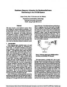
Figure 1. DEIMOS CCD mosaic and FCS CCDs
Figure 2. The DEIMOS mosaic CCD controller
The DEIMOS mosaic CCD controller5 is shown in Fig. 2. It employs these four types of SDSU-2 boards (located in the bottom half of the controller) in combination with three UCO/Lick-designed printed circuit boards: the clock cable, bias cable, and CCD cable interconnect boards; those boards are located in the top half of the controller. Connections between these boards are via ribbon cables that are easily fabricated using insulation displacement connectors. The interconnect boards simplify the signal distribution from the controller to the CCD mosaic dewar by collecting into a single cable for each CCD the various clock, bias, and utility signals for that device, which originate from three separate SDSU-2 boards. The interconnect boards also simplify reconfiguration of the controller for different mosaics or operating modes. The DEIMOS mosaic CCD controller can be configured to provide single-amplifier-per-CCD readout of the 8-CCD mosaic using only four video processing boards, or to provide dual-amplifier-per-CCD readout using eight of those boards. During the first years of testing the mosaic subsystem using engineering-grade CCDs (some of which had only one working readout amplifier), the former configuration was used. Once enough science grade devices with two working readout amplifiers were obtained, four more SDSU-2 video processing boards were purchased and the system re-configured to provide dual-amplifier-per-CCD readout capability. Upgrading the controller from single-amplifier to dual-amplifier-per-CCD readout capability required only the installation of the additional video processing boards, the re-arrangement of the ribbon cables between the various interconnect boards, and the resetting of some jumpers on those interconnect boards.
In the DEIMOS mosaic CCD controller, the clock generation boards all have their switch-state address jumpers set to the same value (address 2) and the video processing boards are similarly jumpered to a common switch-state address (address 0). As a result, the clocks sent to all eight CCDs of the mosaic are generated in parallel and are precisely synchronized; the video processing for each CCD is similarly synchronized. This enables all eight CCDs of the mosaic to be read out in parallel and avoids the increase in read noise that would occur if such synchronization were not maintained.
1.1. The mapping of video outputs to video inputs Each SDSU-2 video processing board provides two independent video channels, labeled “A” and “B”. Each MIT/LL CCID-20 CCD has two readout amplifiers, also labeled “A” and “B”. When configured for dualamplifier-per-CCD readout mode, a logical arrangement is to provide one video processing board for each CCD and to route the “A” and “B” video outputs from each CCD to the corresponding “A” and “B” video inputs of the video processing board for that CCD. Since these boards also generate bias voltages, the video board for a given CCD can be used to generate separate bias voltages for both the “A” and “B” sides of the device. As shown in Table 1, this is the mapping that was used for the DEIMOS mosaic CCD controller. Video Channel Latch Address 0 1 2 3 4 5 6 7 8 9 10 11 12 13 14 15
Video Board DAC Address 0 0 1 1 2 2 3 3 4 4 5 5 6 6 7 7
Video Board Channel A B A B A B A B A B A B A B A B
CCD 1 1 2 2 3 3 4 4 5 5 6 6 7 7 8 8
CCD Amplifier A B A B A B A B A B A B A B A B
Table 1. DEIMOS mapping of CCD amplifiers
Video Channel Latch Address 0 1 2 3 4 5 6 7 8 9 10 11
Video Board DAC Address 0 0 1 1 2 2 3 3 4 4 5 5
Video Board Channel A B A B A B A B A B A B
CCD 1
CCD Amplifier A
1
B
2
A
2
B
3
A
3
B
Table 2. HIRES mapping of CCD amplifiers
Unfortunately, the SDSU-2 video processing boards exhibit very low-level crosstalk (approximately 1 part in 20,000) between the two video channels on each board. While this may not be a concern for many direct imaging applications, it is problematic for multi-slit spectroscopic observations of fields containing a mix of bright and faint objects. In such situations, a further advantage of this mapping of video outputs to inputs (i.e., “A” to “A”, “B” to “B”) is that it provides a workaround to this crosstalk problem. By switching to single-amplifier-per-CCD readout clocks for such observations (with a corresponding penalty in readout time), the mosaic CCDs images can be read out using only one half (i.e., one of the two video input channels) of each video processing board, thereby avoiding the crosstalk problem on these boards. For the HIRES mosaic CCD controller, the decision was made to avoid this inter-channel crosstalk problem by using only half-populated video processing boards (the “B” channel of each board is not used and the components on that half of the board are not installed). As a result, each CCD in the HIRES mosaic connects to two halfpopulated video processing boards, as shown in Fig. 2. Note that only the boards with even-numbered DAC addresses are used for bias voltage generation.
2. TRANSMISSION OF ALTERNATE CHANNELS In the first generation SDSU architecture, programmed I/O was used to transmit the digitized pixel data from the CCD controller to the downstream computer. Software on the timing board would first read the digitized pixel data from the latch on each video processing board and then copy that data into the transmit register for the fiber optic downlink. While this architecture enables the timing board to selectively transmit the pixel data from an arbitrary subset of video processing channels, it consumes a significant fraction of the per-pixel processing time in a multi-channel CCD mosaic system, because the timing board cannot overlap other functions (e.g., generation of serial clocks or processing of CCD video) with pixel transmission. While the SDSU-2 architecture retains this programmed I/O capability, one of its major design improvements is its ability to overlap the transmission of digitized pixel data (over the fiber optic downlink) with these other pixel-processing functions. This is accomplished in hardware by means of two programmable array logic (PAL) circuits, U12 and U17, on the SDSU-2 timing board. To utilize this feature, the software on the timing board stores into a control register in the PAL the starting and ending latch address numbers for the inclusive range of video channels whose latched data is to be transmitted via the fiber downlink. The act of writing that control register triggers the relevant circuitry in these PALs to sequentially access and transmit the digitized pixel data from the specified range of video channels. The DEIMOS mosaic CCD controller makes extensive use of this overlapped-transmission feature. At the end of each pixel processing time slot, the software on the timing board writes into the control register the desired range of video channels to be transmitted. Once that control register has been written, the timing board software can begin the per-pixel processing for the next pixel. As a result, the transmission of the pixel data (for the specified video channels) acquired at pixel time slot N is overlapped with the pixel processing (i.e., serial transfer, video processing, and digitization) for pixel time slot N + 1. Unfortunately, as originally implemented, this overlapped-transmission functionality did not provide sufficient flexibility for the various readout modes of the fully-configured DEIMOS mosaic CCD controller. As can be seen from Table 1, the DEIMOS mosaic and its controller have been configured so that the “A” amplifiers from each CCD occupy the video input channels having even-numbered latch addresses while the “B” amplifiers from each CCD occupy those with odd-numbered latch addresses. Accordingly, for the single-amplifier-per-CCD readout modes, it would be desirable to transmit only the video channels with even-numbered latch addresses (if using only the “A” amplifiers) or those with odd-numbered addresses (if using only the “B” amplifiers). One approach to this problem is to always transmit the pixel data from both the “A” and “B” video channels (even if only one has useful data, as would be the case when reading out in a single-amplifier-per-CCD mode) and to discard the unwanted pixels at the receiving end of the fiber downlink. This approach is feasible as long as: 1) there is sufficient processing power at the receiving end of the downlink to keep up with the higher pixel rate and 2) the effective bandwidth of the downlink is sufficient to sustain that transmission rate. This approach was used implemented by modifying the software in the fiber optic interface board (VMEINF2) that is attached to the receiving end of the downlink fiber; that board resides in the computer (in this case, a VME crate running VxWorks) that receives and buffers the CCD mosaic images. The software for that interface board was modified so that it could be commanded to either accept all pixels or to discard either even-numbered or odd-numbered pixels arriving on the fiber optic downlink. The first mode (accept all pixels) was used when reading out the mosaic in dual-amplifier-per-CCD mode. When reading out in single-amplifier-per-CCD mode, the “discard odd pixels” mode was used if reading from the “A” amplifiers of the CCDs in the mosaic, and the “discard even pixels” mode was used if reading from the “B” amplifiers. This scheme was used to support both the single- and dual-amplifier-per-CCD readout modes during the period that the DEIMOS mosaic CCD controller was operating the first engineering and science mosaics composed of MIT/LL lot 9 and 10 devices. Due to problems that occurred during wafer processing, these devices had marginal serial charge transfer efficiency (CTE) when operated with serial clocks having narrow (i.e., less than 1 microsecond) overlap between serial phases. As a result, these mosaics were operated with relatively slow serial clocks, resulting in a pixel processing time of about 10 microseconds. Such slow pixel processing times taxed neither the processing speed of the fiber optic interface board nor the effective bandwidth of the fiber optic downlink, so this scheme of discarding pixels at the far end of the fiber downlink proved adequate.
However, this scheme was not adequate to support the fastest single-amplifier readout modes for the final DEIMOS science mosaic that was composed of lot 14 MIT/LL devices; those devices achieved excellent serial CTE when operated with serial clocks having only 0.1 microseconds of overlap between serial phases. Those narrow overlaps made possible per-pixel processing times of 5.3 microseconds and that is shorter than the time required∗ to transmit 16 pixels of data down the fiber optic downlink. Because this transmission rate exceeded the bandwidth of the downlink, we could no longer afford the luxury of discarding the empty pixels at the far end of the the downlink.
Figure 3. Schematic for revisions to Timing Board PAL U12 ∗
In the revision 4B timing boards used in DEIMOS, the fiber optic downlink operates at 50 MHz, or 20 nanoseconds per bit. Each digitized pixel is sent as a 16-bit unsigned integer and thus requires 320 nanoseconds for transmission down the fiber. Add to this two DSP clock cycles of 40 nanoseconds each: the first to fetch the pixel data from the digital latch on the respective video processing board via the VME-style backplane bus and the second to write that data into the fiber optic transmitter register. Thus, this overlapped-transmission feature requires 400 nanoseconds (320 + 40 + 40) for each pixel transmitted, yielding an effective downlink bandwidth of 2.5 megapixels/second. The time required to transmit 16 pixels of data is 6.4 microseconds.
To address this limitation, we asked Astronomical Research Cameras, Inc., to explore the possibility of modifying the pixel transmission PAL logic to enable the selective transmission of pixels only from video channels with either even-numbered or odd-numbered latch addresses. They developed such a modification to PAL circuits U12 and U17 on the Rev. 4B timing board (See Figs. 3 and 4). Since these PAL circuits are socketed devices, they are easily changed on the boards in question, enabling the upgraded PALs to be installed at the telescope.
Figure 4. Schematic for revisions to Timing Board PAL U17 This modified functionality is accessed via bits 10 and 12 of the PBD port of the Motorola 56002 DSP on that timing board; the operational definition of those two bits is provided in Table 3. Bit 10 0 1 X
Bit 12 0 0 1
Functionality Transmit only pixels from even-numbered latch addresses Transmit only pixels from odd-numbered latch addresses Transmit pixels from both even- and odd-numbered latch addresses Table 3. New bit definitions for PBD bits
The ability to selectively transmit the pixel data from video channels with either even-numbered or oddnumbered latch addresses proved particularly useful for the HIRES mosaic. As noted in section 1.1, the HIRES mosaic CCD controller employs only half-populated SDSU-2 video processing boards. As such, only the video channels with even-numbered latch addresses contain any data (see Table 2). Accordingly, the HIRES CCD controller always operates with the PBD register configured for “even-only” transmission, and the pixel data from both the “A” and “B” amplifiers of each CCD are always sent down the fiber optic downlink. If the HIRES mosaic is read out in a single-amplifier-per-CCD readout mode, then the unwanted pixels are discarded at the far end of the downlink. Since the HIRES mosaic has only 3 CCDs (and hence only 6 amplifiers), the bandwidth of the fiber downlink is not a concern.
3. SELECTIVE READOUT OF CCDS WITHIN A MOSAIC The HIRES CCD mosaic (slated for installation at Keck during the summer of 2004) consists of a 3 x 1 mosaic of MIT/LL CCID-20 2K x 4K pixel CCDs; these CCDs have 15 micron pixels. This mosaic will replace the existing Tektronix 1K x 1K (24 micron) pixel detector, which has been a part of the instrument since it was commissioned in 1993. The mosaic will provide significantly increased quantum efficiency, especially in the blue. Together with the new mosaic CCD controller, it will reduce the readout time by nearly a factor of 5 and cut the readout noise by nearly a factor of 2. The larger effective detector area will enable most of the HIRES Echelle format to be captured in a single exposure. A goal (although not a requirement) of this detector upgrade project was to provide the hardware hooks that would allow the individual CCDs of the mosaic to be read out separately. Provided that the CCDs in that mosaic do not exhibit any pathological behavior (e.g., glowing amplifiers or serial register pixels) when the serial clocks are operated without corresponding parallel clocks, this goal can be achieved if the CCD controller can be configured so as to generate independently the parallel clocks for each CCD of the mosaic. However, that capability needs to be implemented in a manner that does not compromise the performance of the system when all of the CCDs of the mosaic are read out synchronously. As mentioned in Sect. 1, one of the key features of the SDSU-2 architecture (that enables it to perform efficient clocking of CCDs) is the ability to set the switch-state addresses for all clock generation boards to the same address. By configuring the boards in this way, each clock transition can be sent simultaneously to all of the CCDs of the mosaic, thus significantly reducing the readout time compared to the case where each such transition is separately commanded to each clock generation board. But if one sets all of the clock generation boards to respond to the same switch state address, then it is no longer possible to generate the parallel clocks independently for each CCD, as is needed to achieve the specified goal. One possible solution would be to assign the serial clocks (for all of the CCDs of the mosaic) to a set of clock generation boards whose switch-state address jumpers were all set to the same address, while assigning the parallel clocks for each individual CCD to a separately-addressable clock generation board. This would enable the serial clock waveforms (which need to be generated as rapidly as possible) to be sent simultaneously to all of the CCDs of the mosaic, while enabling the parallel clocks (which operate much more slowly) to be generated separately for each CCD. While such an approach is possible using the standard SDSU-2 architecture, it is incompatible with the existing design for our clock cable interconnect boards and cabling† . Also, for CCD mosaics with an even number of CCDs, this approach would require more clock generation boards and more slots in the VME-style backplane of the CCD controller. Further, to simplify sparing and troubleshooting, we wanted to use the same interconnect scheme as was used in three other SDSU-2 CCD controllers already in use at Keck Observatory (the ESI CCD controller, the DEIMOS mosaic CCD controller, and the DEIMOS FCS CCD controller). In addition, maintaining the identical mappings of CCD clock signals to clock generation boards simplified documentation and enabled re-use of identical MIT/LL CCD waveforms as used in the ESI and DEIMOS systems. †
The SDSU-2 clock generation boards provide 24 clocks per board. These are divided into two banks of 12 clocks each. Each set can be individually addressed, or both banks can be addressed in parallel. Our interconnect board design assigns the 12 clocks for each MIT/LL CCD (9 serial clocks plus 3 parallel clocks) to one of these two banks. Thus, each clock generation board can generate the clocks for two MIT/LL CCDs.
3.1. Broadcast address for clock generation boards Our solution was to propose a change to the PAL circuit (U100) that performs the switch-state board-address decoding‡ for the clock generation boards (See Fig. 5). This modification defines clock generation switch-state board address 12 to be a wild-card or broadcast address. With the modified version of the U100 PAL installed, a clock generation board will respond if the switch-state address currently asserted on the VME-style backplane (input signals SS12 through SS15) matches: 1) the value of the switch-state address jumpers on that board (input signals SADD5 through SADD7), or 2) switch-state address 12 (the broadcast address). U12
(#13) TIM_A_ENCK
CLKEN (#27)
x y
U13
(#16) TIM_A_CDAC
DAC_CLR (#26)
x y
U5 U3
ay
a b c
U4
(#3)SS12
GND U6
y
U10
a y
ay
d
U18 s
b
x y
q r
(#19)
A(0)
(#4)SS13 (#5)SS14 (#6)SS15
A(1) A(2) B(0)
(#9) SADD5 (#10)SADD6 (#11)SADD7
B(1) B(2)
U2
U1 A(0:2) B(0:2)
U7
a y
A(0:2)
OE
y
U11
a y
b B(0:2)
d
U19 s
b
x y
q
U14
OUT_LTCH_B
(#18)
r
COMP3
x y
(#12) MODE
U9
a
b
OUT_LTCH_A
U8 a b c
y
U15
U16
a y
a
b
ADD_E (#23)
(#2) TIM_A_WRSS
y b
U17 ay
Figure 5. Schematic for revisions to Clock Generation PAL U100
3.2. Different addressing modes for parallel and serial clocks With this modified U100 PAL circuit installed, the two clock generation boards in the HIRES mosaic CCD controller have their switch-state address jumpers set to distinct values,§ enabling each CCD in the mosaic to be clocked individually, if desired. However, by defining clock waveforms that reference the switch-state broadcast address (12), all of the CCDs in the mosaic can be clocked in unison. Accordingly, the parallel clock waveforms for the HIRES CCD mosaic are defined in terms of the individual switch-state addresses so that the parallel clocks can be sent independently to a single CCD or to a subset of the CCDs in the mosaic. The serial clock waveforms for the mosaic are defined in terms of the switch-state broadcast address so that the the serial clocking of all of the CCDs in the mosaic occurs in unison. Since the switch-state addresses for the video processing boards are also set to a common address (address 0), the video processing for all of the CCDs in the mosaic also occurs in unison. ‡
Currently, the switch state address for each board can be set to an even-numbered value between 0 and 14. The top bank of 12 clocks on each board is addressed via the even-numbered switch state address value encoded by the setting of that board’s address jumpers, while the bottom bank of 12 clocks is addressed via the next higher (odd-numbered) address. However, if bit 1 of the timing board’s WRLATCH register is set to 1, then both the top and bottom banks of clocks are addressed simultaneously whenever the even-numbered switch state address is referenced. § The clocks for CCD 1 and 2 are generated, respectively, by the top and bottom banks of clocks on the clock generation board at switch-state address 2, and the clocks for CCD 3 by the top bank of clocks on the board at address 4. Thus, the clocks for each of the three CCDs in the mosaic can be addressed individually using switch state-addresses 2, 3, and 4.
4. SOFTWARE FOR TAKING SUB-EXPOSURES WITHIN A MOSAIC When observing a relatively bright object with a steep spectral gradient (e.g., one that is significantly brighter in the red than in the blue), if one exposes long enough to achieve high signal-to-noise at the blue end, the red end may be overexposed. Conversely, if one sets the exposure time to avoid saturation in the red, the blue end may be insufficiently exposed. In other cases, an object may be sufficiently faint that over-exposure is not a concern on any CCD, but the exposure at one end may integrate above the readout noise more rapidly than on the CCD at the other end. In either case, when integrating on such objects, it may be advantageous to be able to read out some of the devices of the mosaic more often than others. The spectral distribution across the HIRES mosaic is shown in Fig. 6. The mosaic is positioned such that the blue end of the HIRES Echelle format falls on the CCD in position 1 and the red end falls on the device in position 3. The anti-reflection coating on each CCD has been optimized to provide the best transmission for the wavelength range that will fall on each each detector. Hence, the CCD in position 1 is referred to as the Blue, or “B” CCD, the device in position 2 as the middle, Green, or “G” CCD, and the device in position 3 as the Red or “R” CCD. PIXEL 6144,4096
FOCAL PLANE Y
PIXEL 1,4096
FOCAL PLANE X
POSITION 2
POSITION 1
PIXEL 1,1
A
SERIAL READOUT
B
A
2
3
BLUE CCD 1
SERIAL READOUT
POSITION 3
B A
SERIAL READOUT
PIXEL B 6144,1
RED CCD
MID CCD 4 5
6
3 MIT/LL 2048x4096 15Pm PIXEL CCD'S
Figure 6. HIRES CCD mosaic
Figure 7. The MSE sub-panel on the HIRES GUI
The ability to generate distinct parallel clocks for each CCD of the mosaic enables a new type of exposure mode which we refer to as a sequence of multiple sub-exposures (MSE). At the end of such an MSE sequence, the total exposure time for each CCD of the mosaic is the same. However, during the sequence, some CCDs are read out more often than others, depending on the spectral gradient across the mosaic. For example, assume that the HIRES mosaic is being used to obtain the spectrum of an object which is much brighter in the red than in the blue. Further assume that a 3600 s exposure is needed to obtain sufficient signal to reach above the readout noise of the Blue CCD, that only a 1800 s exposure is needed to get above the readout noise of the Green CCD, and that only a 1200 s exposure is needed for the Red CCD. By taking an MSE sequence consisting of three 1200 s exposures on the Red CCD, two 1800 s exposures on the Green, and one 3600 s exposure on the Blue, one could perform more effective cosmic ray removal on the Red and Green devices, since they would be read out more frequently. At the end of the MSE sequence, all three CCDs of the mosaic would have integrated for a total of 3600 s on the given object. Table 4 provides a detailed breakdown that shows how the example MSE sequence (described above) would be carried out. This breakdown assumes an erase cycle time of 7 seconds and a readout time of 35 seconds. Note that four separate exposures are taken in this sequence, and that for each exposure, only a subset of the CCDs in the mosaic are erased or read out. Because four separate exposures are taken, the total MSE sequence takes 3768 seconds versus the 3642 seconds required to obtain a single 3600 s exposure over the full mosaic, or about a 3.5% increase in the time required to conduct the observation.
Elapsed Time 0 7 1207 1242 1249 1849 1884 1891 2491 2526 2533 3733 3768
Shutter State Closed Open Closed Closed Open Closed Closed Open Closed Closed Open Closed Closed
Global Exposure Time 0 0 1200 1200 1200 1800 1800 1800 2400 2400 2400 3600 3600
SubExposure Time 0 0 1200 0 0 600 0 0 600 0 0 1200 1200
Red CCD Erasing Exposing Reading Erasing Exposing Pausing Pausing Exposing Reading Erasing Exposing Reading Idle
Green CCD Erasing Exposing Pausing Pausing Exposing Reading Erasing Exposing Pausing Pausing Exposing Reading Idle
Blue CCD Erasing Exposing Pausing Pausing Exposing Pausing Pausing Exposing Pausing Pausing Exposing Reading Idle
Table 4. An example sequence of multiple sub-exposures Commands to the HIRES instrument are expressed in terms of KTL6 keyword operations.7 All Keck optical instruments currently use a common set of keywords to initiate CCD exposures. These keywords can be hidden from the observer by providing a graphical user interface (GUI) which writes the relevant keywords in response to user input, such as clicking on an “EXPOSE” button on the GUI. Alternatively, keywords can be written from a script or directly from the command line of the user’s shell. For example, the two primary keywords used to initiate CCD exposures for Keck optical instruments are TTIME and EXPOSE; to start an 1200 s exposure, one would set TTIME = 1200 and EXPOSE = true. To implement the MSE sequence mode, only a few new CCD keywords needed to be defined. The MOSMODE keyword is a read/write keyword that specifies which of the three CCDs of the mosaic will be read out at the end of the current sub-exposure. The ERAMODE keyword is a read-only keyword that the CCD controller sets to the current value of MOSMODE at the start of each readout; ERAMODE indicates which CCDs of the mosaic will be erased at the start of the next sub-exposure. If any sub-exposure is aborted, the entire MSE sequence is aborted, and both keywords are reset to their default values. When an MSE sequence is not being taken, the MOSMODE and ERAMODE will both be set to their default values of ‘B,G,R’, which means that all of the CCDs will be erased in unison at the start of the next exposure and that all of the CCDs will be read out in unison at the end of that exposure. To obtain the MSE sequence described in Table 4 above, the following sequence of keyword writes would be performed: (MOSMODE = ‘R’ TTIME = 1200 EXPOSE = true); (MOSMODE = ‘G’ TTIME = 600 EXPOSE = true); (MOSMODE = ‘R’ TTIME = 600 EXPOSE = true); (MOSMODE = ‘B,G,R’ TTIME = 1200 EXPOSE = true). To simplify the setting of these keywords, a script has been written which takes as parameters the global exposure time (e.g., 3600 s in this example), and the number of sub-exposures to take for each of the three CCDs of the mosaic (e.g., in this example, 3 for the Red CCD, 2 for the Green, and 1 for the Blue). To further simply use of this observing mode by the astronomer, a sub-panel has been added to the HIRES CCD exposure control GUI.8 Text entry fields on that sub-panel enable entry of these 4 parameters. The GUI sub-panel also provides a graphical display of the current progress of the MSE sequence (See Fig. 7). At the right of the sub-panel are rectangles representing each of the three CCDs of the mosaic. Each rectangle is filled with different color depending its current state: gray if erasing, green if exposing or pausing, gold if reading out, and empty (unfilled) if idle. The challenge was to represent the more complicated state of detectors in the MSE mode, since they are not merely erasing or exposing or reading out; rather, they can also be “not-erasing”, or “dirty” (preserving charge from previous exposure) if they have not been selected for erasure on this cycle, and “not-reading-out” if they have not been selected for readout. We settled on a bold diagonal stripe effect to mark chips in this state. To show which CCDs will be read out at the end of the current sub-exposure, a gold box appears around the identifying initials of the CCDs that will be read.
5. UTILITIES FOR COMBINING SUB-EXPOSURES INTO A SINGLE FITS FILE A complete implementation of all the features for the multiple sub-exposure (MSE) capability requires significant changes in the existing software, both on the HIRES CCD VME crate and in the image capture processes. Because these features were not required for delivery of the HIRES mosaic not all of the necessary changes have been implemented. The most archivally significant omission is that the pixels from the CCD amplifiers involved in each sub-readout are written into a separate multi-extension FITS (MEF) file. The keywords in the primary header/data unit (PHDU) of these separate FITS files document the situation only at the time of the shutter opening and closing of the most recent sub-exposure. While the exposure time keywords are correct for any CCDs which were erased just before the most recent shutter opening, they are not correct for any CCDs which were previously partly exposed and not erased. Nevertheless, the PHDU keywords do contain enough information to reconstruct correct values for almost everything. Therefore it is possible to construct a post-processing script to remedy the archival situation. The keywords which contain the most easily recognized indication of a MSE sequence are the string-valued MOSMODE and ERAMODE keywords. For the HIRES mosaic, MOSMODE and ERAMODE can have the value of ‘B, G, R’, any other comma-separated subset of these letters, or ‘NoCCD’. The letters correspond to the spectral layout of HIRES cross dispersion, where ‘B’ is the CCD receiving the bluest light, ‘R’ is the CCD receiving the reddest light, ‘G’ is the CCD in the middle. (‘NoCCD’ is provided for completeness to indicate an unusual situation where none of the CCDs was read or erased.) The MOSMODE value indicates which of the CCDs will be (or were) read at the end of the next (or most recent) exposure. The ERAMODE value indicates which of the CCDs were erased at the beginning of the most recent exposure. When MOSMODE and ERAMODE are both ‘B, G, R’, it is reasonable to infer that the exposure is not part of a MSE sequence. When ERAMODE is ‘B, G, R’ and MOSMODE is not, that FITS file can be inferred as the beginning of a MSE sequence. The end of a MSE sequence is implied when MOSMODE has the value ‘B, G, R’ and ERAMODE does not. In order to provide a more generic and more introspective view of the exposure characteristics, there are other keywords indicating the status of each CCD amplifier. The integer-valued VIDINBEG and VIDINEND keywords correspond, respectively, to the ERAMODE and MOSMODE keywords. The bits in each keyword indicate the amplifiers whose CCDs were erased or read. Bit 0 corresponds to the amplifier named 1 on the engineering drawing of the mosaic, and for HIRES this sequence continues such that bit 5 corresponds to amplifier named 6. The HIRES mosaic is currently constrained such that parallel shifts must occur for both of the amplifiers on a single CCD. Therefore the bits always agree in adjacent pairs, and an image not part of a MSE sequence has VIDINBEG and VIDINEND values of 63. The data acquisition software inserts one other keyword, VIDINACT, with identical characteristics. The bit values in VIDINACT indicate which CCD amplifiers corresponded to the pixels transmitted from the CCD subsystem during the readout. The HIRES mosaic system currently produces only values that correspond to all three ‘A’ amplifiers, all three ‘B’ amplifiers, or all six amplifiers. We have a prototype post-processing script named joinsubexp which identifies and combines the FITS files produced by MSE sequences. When given a directory full of HIRES mosaic FITS files, joinsubexp first examines the keywords in the PHDUs to identify which, if any, of the files were members of MSE sequences. The script then combines all of the IMAGE extensions from each MSE sequence into a single, very large, MEF file. Unlike the original FITS files from the data acquisition system, the PHDU of the combined file is largely void; it does not contain the keywords describing the instrument and telescope configuration. (No single set of keyword values in the PHDU of the combined file can adequately describe the information from the many files in the MSE sequence.) After copying each IMAGE extension into the combined file, the script copies the keywords from the PHDU of the original file into the new IMAGE extension. Finally, the script reconstructs the correct values for each of the time-sensitive FITS keywords and writes them into the individual IMAGE extensions. The time-related keywords that require rewriting fall into four categories: Begin, Sum, End, and History. The Begin category contains keywords whose values should reflect the begin time for the exposure in a particular IMAGE extension. The Sum category contains keywords whose values should reflect the sums of the values of those keywords in all of the original PHDUs of the MSE sequence. The End category contains keywords whose values should reflect the end time for the exposure in a particular IMAGE extension. The History category
contains keywords whose values are not reconstructible or not relevant to the combined MEF file. Keywords in the History category are copied into the combined IMAGE extensions as FITS HISTORY cards.¶ Although the combined MEF file produced by joinsubexp conforms to the FITS standard, it deviates from previous local conventions. Such files raise unanswered questions about how they will be tolerated by data reduction and archiving systems.
6. CONCLUSION By making minor modifications to the socketed PAL circuits on the SDSU-2 timing and clock generation boards, we have been able to extend the capabilities of the SDSU-2 architecture in ways that make new observing modes possible for CCD mosaics. The PAL modifications described here enable CCD mosaics to be read out in a variety of different configurations and with optimal readout efficiency. However, the mechanisms for addressing the banks of clocks on the clock generation boards and for accessing the digital latches on the video processing boards are still not as generalized as one would like. For example, these mechanisms still do not provide an efficient method for addressing a mix of ‘A’ and ‘B’ amplifiers when operating in the single-amplifier-per-CCD readout mode. Although the existing SDSU-2 architecture enables such a mix of amplifiers to be read in that mode, it cannot be done without either incurring a penalty in readout time or requiring a hard-wired exchange of serial clock phases on a clock interconnect board. More flexible addressing schemes should be considered in future iterations of the pixel transmission PAL logic (U12 and U17) on the timing board and the switch-state board address decoding logic (U100) on the clock generation board.
ACKNOWLEDGMENTS We would like to thank Bob Leach and the staff at Astronomical Research Cameras, Inc. for developing the modified PAL circuits described here and for his help in debugging some of our unique timing requirements.
REFERENCES 1. R. Leach, F. Beale, and J. Eriksen, “New generation CCD controller requirements and an example: the San Diego State University generation II controller,” in Optical Astronomical Instrumentation, S. D’Odorico, ed., Proc. SPIE 3355, pp. 512–519, 1998. 2. S. S. Vogt et al., “HIRES: The High Resolution Echelle Spectrometer on the Keck Ten-Meter Telescope,” in Instrumentation in Astronomy VIII, D. L. Crawford, ed., Proc. SPIE 2198, pp. 362–375, 1994. 3. S. Faber et al., “DEIMOS spectrograph for the Keck 2 telescope: integration and testing,” in Instrument Design and Performance for Optical/Infrared Ground-Based Telescope, M. Iye, ed., Proc. SPIE 4841, pp. 1657– 1669, 2003. 4. B. E. Burke et al., “CCD imager technology development at Lincoln Laboratory,” in Optical Detectors for Astronomy II: State-of-the-Art at the Turn of the Millenium, P. Amico and J. W. Beletic, eds., p. 187, Kluwer, (Boston), 2000. 5. C. Wright, R. Kibrick, and B. Alcott, “CCD imaging systems for DEIMOS,” in Instrument Design and Performance for Optical/Infrared Ground-Based Telescope, M. Iye, ed., Proc. SPIE 4841, pp. 214–229, 2003. 6. W. F. Lupton and A. R. Conrad, “The Keck Task Library (KTL),” in Astronomical Data Analysis and Software Systems II, R. J. Hanisch, R. J. V. Brissenden, and J. Barnes, eds., ASP Conference Series 52, pp. 315–320, 1993. 7. A. R. Conrad and W. F. Lupton, “The Keck Keyword Layer,” in Astronomical Data Analysis and Software Systems II, R. J. Hanisch, R. J. V. Brissenden, and J. Barnes, eds., ASP Conference Series 52, pp. 203–207, 1993. 8. D. Clarke, “Dashboard: a knowledge-based real-time control panel,” in Proceedings of the 5th Annual Tcl/Tk Workshop, pp. 9–18, 1997. ¶
The semantics of each of http://www.ucolick.org/˜sla/fits/
these
keywords
is
available
online
via
the
dictionary
bundle
links
at