from business analysis and simulation to subsequent detailed UML software de .... (OMG) in 2001 and is the most used software methodology based on the UML.
Organization Modeling and Simulation using BORM Approach No Author Given
No Institute Given
This paper presents the BORM approach in the organizational modeling and simulation. The �rst part of this paper presents the BORM analysis and design methodology, which has proved to be e�ective in the development of business systems. The second part of this paper shows an example from our regional management project concerning the analysis of the legislation and local o�cials' knowledge. The project has been related to the processes and agendas of the urban planning of the landscape areas and small settlements with regards to the new housing and building law and regional management trends in the European Union. Our methodology presents necessary aspects of the relevant organizational model without need of deep prior training. Our models were simulated, veri�ed and validated in order to help the o�cials (especially from the smallest settlements) to improve their knowledge. Abstract.
organization structure modeling, organization structure simulation, BORM, regional management. Keywords:
1
Introduction
The Organization Modeling is a vital part of the entire information development process. Darnton [7] and Taylor [30] write, that the major problem (interpreted from viewpoint of the software engineering) with this so-called requirement analysis of organization systems arises in the initial stages of the entire information system development cycle. The initial stage of any methodology today should be concerned with two tasks. The �rst is the speci�cation of the requirements for the system. The second is the construction of an initial object model, often called an essential object model or conceptual model, built from of a set of domain speci�c objects known as essential objects. Both these tasks should be carried out with the active participation of the stakeholders, in order to ensure that the correct system is being developed. Consequently, any tool or diagram used at these early stages should be comprehensible to the stakeholders, many of whom are not 'computer system literate'. Moreover, these diagrams must not deform or inadequately simplify requirement information. The most common technique for requirements speci�cation in current objectoriented methodologies is Use Case modeling as the start of UML documentation process. The concept of use-cases has been introduced by Jacobson in the early
1990s [16]. The main information source about UML is the web-site [31]. As Ambler [1] states, Use Cases are often the foundation of most object-oriented development methods. Use Case modeling is concerned with the identi�cation of actors, which are external entities interacting with the software part of the system. This means that in order to employ Use Case modeling, it is necessary for developers to already know the system boundary and distinguish between entities, which are internal and external to that boundary. It is our experience that the correct identi�cation of the system boundary is a `non-trivial' task, which often requires signi�cant understanding of the proposed system and consequently can only successfully take place at the end of the requirements speci�cation stage. Some de�ciencies in this approach are also highlighted by Barjis in [2]. There are many views on the e�ectiveness of Use Cases and related tools as a �rst stage in System Design. Simons and Graham [29] for example describe a situation where Use Case Modeling obscures the true business logic of a system. Because of standard UML-based tools are too oriented at the world of programming concepts, other methods for business logic and process modeling appeared: 1. The basic grammar of other process modeling tools is based on Petri Nets. The strengths of this approach are that it is both graphical and has strong mathematical basis. A practical implementation of Petri Nets is the EPC diagram of Aris methodology [10], for example. 2. Another techniques are based on miscellaneous varieties of �owchart diagrams. This approach is the oldest diagramming technique used in computer science. It was primarily used for visualizing the sequences of operations in computer programs. Today, �owcharts are frequently used to model business processes. A practical implementation of �owcharts is work�ow diagram used in Proforma Workbench or FirstStep Business CASE Tools. Indisputably, it is also a kind of the Activity Diagram of UML [12]. 3. The third technique used here is the use of state machines. These have the theoretical background ([28] for example), as well as Petri Nets. A practical implementation of state machines is state-chart diagram in UML, for example. Indeed, the sequence diagram of UML has features of state machines as well. The overview of all approaches for modeling business logic and processes described here is presented in table 1.
2
Our Experience
Our experience in system modeling suggests that classical UML is not suitable for �rst stages of analysis, where business processes need to be recognized. UML diagrams are too complex for the users from the problems domain community as they often contain too much detail concerning potential software implementations. This means classes, inheritance, public/private methods, attributes, link
Table 1.
approach EPC � Aris
UML Activity Diagram or BPMN
The most used organization modeling approaches.
theory advantages behind Petri Very popular in Europe, Nets perfectly supported by Aris CASE Tool, easy and comprehensible method for domain experts. FlowchartIndustry standard, supported by many CASE tools with UML (Uni�ed Modeling Language) or BPMN (Business Process Modeling Notation). Finite Industry standard, supported state by many CASE tools with UML machine (Uni�ed Modeling Language).
UML sequence and state-chart diagram Work�ow FlowchartEasy and comprehensible Diagrams method for domain experts, perfectly supported by many business CASE Tools.
disadvantages Weak relation at subsequent software development techniques, slow analysis, low expressiveness of large models. Too software-oriented, di�cult to understand by domain experts. Too software-oriented, di�cult to understand by domain experts. Weak relation at subsequent software development techniques, not very popular in Europe where Aris takes the dominant place.
classes, etc. Almost the same experience we have is documented in Simone and Graham [29]. We believe that the business community needs a simple yet expressive tool for process modeling; able to play an equivalent role to that played by EntityRelation Diagrams, Data-Flows Diagrams or Flow-Charts over the past decades. One of the strengths of these diagrams was that they contained only a limited set of concepts (about 5) and were comprehensible by problem domain experts after few minutes of study. Unfortunately UML approach lost this power. That is why we developed our own BORM process diagram and our own way to start business system analysis. It is a simple methodology going smoothly from business analysis and simulation to subsequent detailed UML software design based on MDA software-oriented concepts necessary for the construction of software-oriented conceptual model.
2.1
System Development
Developing systems is a complex activity fraught with many di�culties for software engineers as they endeavor to ensure that the right system is built. A right system being one that meets the user's needs at a cost they can a�ord. On the surface this would appear a straightforward task, �rst year university students studying system design are often surprised when it is pointed out to them that incorrectly specifying the required system is one of the major causes of software systems failure. Such students, however, have little experience of the
complexity of the real world where software developers and experts from the user domain appear to live in di�erent universes, each with their own jargon, which acts as a barrier to true communication. It is in this context that software developers face the �rst and perhaps major challenges of software development; to fully understand the user domain and moreover to convey their understanding of that domain to the user. Adele Goldberg [14] uses the term �concept space� to describe what the user/experts believe, assumes or knows to be the case. The �articulation space� is what the expert/user communicates in response to the analyst's questions. The analyst then constructs a model to feed back to the user/expert their mental model of the concept space, which they construct out of the information presented in the articulation space. The di�erence between this analyst's model and the user space is the concept gap. To a certain extent, part of this gap is unbridgeable; we cannot easily reduce the gap between concept and articulation space as these exist in the user/expert's head. It is true, however, that the languages, natural and graphical, used by the analyst in representing this model, are a vital component in the user/expert's ability to validate this model against the users own concept space. The problem is to �nd a common language for the developers to express their understanding of the problem space that is both su�ciently rich for the developers to fully articulate their ideas while also being comprehensible to users from all areas of discourse. Use-Case has become a well-accepted part of object-oriented analysis and in many cases has proved a useful mechanism for communication between developers and domain experts. We do not intend to discuss it further here. However, Fowler [12] highlights some de�ciencies in the Use-Case approach and also sug-
Activity diagrams can be useful in cases in which work�ow processes are an important part of the users' world." gests that "
Same as [7], we think that activities are a key component of business process modeling. Eeeles and Sims [9] de�ne a business process consisting of a number of elements; activities, transitions, states and decisions. They state that the UML activity-diagrams can be a useful modeling tool in capturing business processes as well. Initial analysis diagram should support only problem domain-speci�c concepts; any software-orientated concepts can be left until later in the modeling process. This is in sharp contrast with UML, which claims to be a universal system; meaning that the same notation is used for analysis, design and documenting the implementation. Our reasons for this requirement are based on the observation that this universality of the UML's notation hinders the design process. In this we are in broad agreement with the criticism of this aspect of UML expressed by Simons and Graham [29]. It is necessary for the organization modeling and subsequent simulation, that every paricipaiting object should be viewed as a state machine with states and transitions dependent on the behavior of other objects. Each state is de�ned by its semantic rule over object data associations and each transition is de�ned by its
behavior, necessary to transform the object from its initial to its terminal state. Organizational and business process model must be able to be simulated. Hence it should accent the mutual relationships (communications and associations) of states and transitions of objects in the modeled system.
3
The BORM Approach
3.1
Motivation
Development of the BORM methodology started in 1993. At that time, several "�rst generation" object or semi-object-oriented analysis methods (OMT, Martin-Odell, Booch, Coad-Yourdon, Jacobson, etc.) existed. These methods were, and still are, very useful for the development of hybrid software systems. For example an object-oriented client talking to a number of relational servers. However the authors felt that these methodologies possessed two fundamental weaknesses which made them inappropriate for their own development requirements. Firstly these existing methods did not o�er su�cient support for development using a pure object-oriented language like Smalltalk. When developing systems in Smalltalk the authors often used constructs of the language like polymorphism between objects without any inheritance or object dependency, which were not supported and could not be expressed in any of these existing development methodologies. Also in the diagrammatic notations they provided it was impossible to represent most pure object-oriented algorithm. Such algorithms may often be described as mutual asynchronous communications (message passing) between objects, which as the result of receiving messages invoke internal methods with a consequential change in their state. Secondly, these existing methodologies initially commenced with the construction of a set of classes showing inheritance and aggregation hierarchies. While this is an e�ective way of expressing the structure required for subsequent coding in an object-oriented language, it is not however e�ective in illustrating the problem domain. This is because the "object oriented nature" of these diagrams are di�cult for domain experts, not educated in computer science concepts, to understand. Consequently such diagrams cannot be used in describing proposed solutions to clients.
3.2
BORM Projects
The initial work on BORM was carried out under the support of the Czech Academic Link Programme (CZALP) of the British Council, as part of the VAP-
1 research project; further development has been carried out with the
PIENS
VAPPIENS was funded by the British Governments CZALP, administered by the British Council. The authors acknowledge the support they received from this source, which enabled them to meet and carry support of Deloitte Central Europe. (
1
Visual Application Programming Paradigms for Intergated ENvironmentS
out the initial work, out of which BORM grew.)
BORM has been used for a
number of large projects including
� � � �
the identi�cation of business processes in Prague city hospitals, the modeling of properties necessary for the general agricultural commodities wholesale sector in the Central European region, as a tool for business process reengineering in the electricity supply industry and as a tool for business process reengineering for telecommunication network management in the Central European region.
3.3
BORM fundaments
BORM is a uni�ed approach to business and IT system modeling. For more on the BORM method see [18,20]. BORM is based on the spiral model for the development life cycle as described in [5]. One loop of the object-oriented spiral model contains stages of strategic analysis, initial analysis, advance analysis, initial design, advanced design, implementation and testing. 1. The �rst three stages are collectively refereed to as the expansion stages. Expansion ends with the �nalizing of the detailed analysis conceptual model, which fully describes the solution to the problem from requirements point of view. 2. The remaining stages are called as consolidation stages. They are concerned with the process of developing from "expanded ideas" to a working application. During these the conceptual model is step by step, transformed into a software design.
Object-oriented approach.
The object-oriented approach has its origins in
the researching of operating systems, graphic user interfaces, and particularly in programming languages, that took place in the 1970s. It di�ers from other software engineering approaches by incorporating non-traditional ways of thinking into the �eld of informatics. We look at systems by abstracting the real world in the same way as in ontological, philosophical streams. The basic element is an object that describes data structures and their behavior. In most other modeling approaches, data and behavior are described separately, and, to a certain extent, independently. OOP has been and still is explained in many books, but we think that this one [14] written by OOP pioneers belong to the best.
Automata theory.
In the �eld of theoretical informatics, the theory of au-
tomata is a study of abstract automatons and the problems they can save. An automaton is a mathematical model for a device that reacts to its surroundings, gets input, and provides output. Automatons can be con�gured in a way that the output from one of them becomes input for another. An automaton's behavior
is de�ned by a combination of its inner structure and its newly - accepted input. The automata theory is a basis for language and translation theory, and for system behavior descriptions. Its usage for modeling and simulation in software engineering activities has been described in [28] and many newer publications. The idea of automata also inspired behavioral aspects of the UML standard [31].
Three areas of BORM modeling in MDA perspective.
MDA (Model-
Driven Approach) is a software development methodology. It provides a set of guidelines for the structuring of speci�cations, which are expressed as stepby-step transformed models. It was created by the Object Management Group (OMG) in 2001 and is the most used software methodology based on the UML (Uni�ed Modeling Language)[31]. BORM can be regarded as a special kind of MDA. In the MDA terminology, we can describe BORM as: 1. The CIM (Computer-Independent Model) modeling, according to the BORM method, is a visualization of the environment in which a project is being executed. It deals primarily with business process models. Its aim is to understand and describe a problem and �nd a solution. A well-made CIM model enables proper descriptions of settings for information system to be made; a necessary condition for a designed solution. This part of BORM having the special BORM process diagram used for the organizational modeling and simulation is discussed in this paper. 2. PIM (Platform-Independent Model) modeling, according to the BORM method, is a visualization of the required information system in software engineering concepts. The UML (Uni�ed Modeling Language) standard has an important role. There is a set of transforming rules [24] from BORM models to the conceptual UML models [23]. 3. The PSM (Platform-Speci�c) model is a revised form of the PIM model which, unlike PIM, enables speci�c software implementation, since it includes speci�c properties of the target environment and reused artifacts of the IT architecture, etc. There is also a set of transforming rules from PIM UML models to the PSM UML models [23].
3.4
BORM CIM � organizational modeling
The �rst part of the method (CIM) covers the organizational modeling. It transforms a project assignment into a model described by miscellaneous hierarchies, process participants, process scenarios, various diagrams and generated reports. The main instrument of veri�cation and validation is the process simulator, which is currently implemented in the Craft.CASE tool [6]. For the following purposes, it is possible to use this part of BORM without any relation to a software engineering phase or organizational structure improvement as is it also presented in the example of this paper. BORM CIM modeling has been used as:
1. Projects documenting processes and organizational structure. These are, for instance, projects whose aim is knowledge management, creating training materials, knowledge visualization, etc. 2. Projects for preparing the groundwork for selection procedures for organizational consultancy, or other consultancy services. 3. Projects for preparing the groundwork for selection procedures for the delivery of information systems, or other software engineering projects. BORM was initially developed as an object-oriented method for the analysis and design of object-oriented software systems. The process (described by Satzinger [27]) starts from an informal problem speci�cation and provides both methods and techniques, to enable this informal speci�cation to be transformed into an initial set of interacting objects. The tools and techniques developed for requirement analysis and used in the initial phases of BORM, provide an independent method for business process modeling as part of business process reengineering. The authors �nd that this independent method, referred to as BOBA (BORM Object Behavior Analysis) is frequently used alone. One advantage of this approach is that it provides a close interactive interchange between the developers and members of the user's organization. As well as identifying initial objects, BOBA elicits from the domain experts, detailed descriptions of their requirements which are fed back to them via easily understood descriptions of the proposed system's behavior using a number of tables and graphs. The problem speci�cations from which the process starts are obtained from relevant parties in the problem domain by interviewing. This determines a list of required system functions, which are essentially Use Cases. From this list, a set of system scenarios is formed. BOBA scripts always include at least the four sections shown in Table 2.
Table 2.
Scenario structure in BORM.
section name description initiator A brief verbal description of the beginning of the scenario including any inputs or entry conditions. It also describes the �rst event or �rst activity of some element within the process. action A verbal description of the process itself. participants The set of those members of the system, which are required for the action. It is often the case that the same participants may be present in several processes of the modeled system. result A brief verbal description of the end and outputs of the scenario.
This structure from table 2 represent the four most important attributes of each scenario. The complete set of scenarios is capable of describing system behaviors, as well as determining the objects that perform these behaviors. In addition to those four attributes each scenario must also refer to the required system function it realizes.
3.5
BORM business diagram
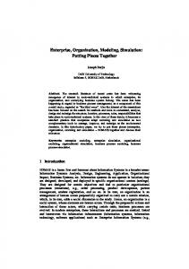
BORM uses an original diagram for business process modeling and subsequent simulation (see �gure 1). It conveys together information from three separate UML diagrams:
state, communication and sequence. The BORM group has found
that it is clearly understood by business stakeholders. Main principles of the BORM process diagram are:
Element
Graphic symbol
Description
Begining of the role
Begining of the action flow of a role.
End of the role
End of the action flow of a role.
Participant = WHO performs the role
Participant has some activities in the process
Activity = WHAT is done in the role
Every action is done by somebody in BORM. Activity is an active or passive (invoked by another participant) action.
State = WHEN something happens
Point in time where the process waits or something is done.
Communication
Control flow between activities. Crossed symbol indicates conditional communication.
Data flow
Exchange of information, data, money, etc.
Transition between states
Linkup between states in time. Crossed symbol means conditional transition.
Association = RELATION between participants
Connection or relation between participants (eg. ownership, dependency, ...).
Participant hierarchy = „IS-A“ taxonomy
When it is necessary to show that a participant is a special type of another participant.
Fig. 1.
BORM diagram symbols.
1. Each subject participating in a process is displayed in its states and transitions. 2. This diagram expresses all the possible process interactions between process participants. The business process itself consists of a sequence of particular communications and data �ows among participating subjects.
More formally, BORM process diagrams are graphical representations of interconnected Mealy-type �nite state machines of particular subjects. Visual simulation of a business process is based on market-graph Petri net. This similar approach is described in detail by [3]. Therefore we can show states, transitions and operations for all subjects playing a role in a business process. This is a very powerful, yet simple diagram.
4
BORM Application Example �Public Regional Management System.
One of the recent BORM applications of organizational modeling and simulation was the project of improvement the decision-making on the level of mayors and local administrations. It o�ers the possibility to model and simulate real life situations in small settlements. The project activities were for modeling, simulation and reengineering processes related to the regional government processes of small towns and villages, and the subsequent development of supporting information systems addressing life situations of local people. Nowadays we have to solve many problems related to the small settlement development and expansion, landscape care and over-all e�orts to improve the quality of life and the level of democracy while preserving the conditions of the sustainable development (addressing living standard, cultural and historic value, agricultural and industrial production, transport infrastructure construction, tourism potential, etc.).
urban urban sprawl in
One of the speci�c problems that our approach can be applied to is the
sprawl
as it is stressed by Frumklin in [13]. The cause of the
the small settlement development is the fact that the elected members of local administrations (e.g. mayors and clerks) are not (and as the logic states they cannot be) fully educated in all the details of law, state and local administration agenda and their e�ects on living in the settlements. They don't know how to use fully the legislation in favour of the settlements and usually depend on a misleading interpretation provided by their governing bodies and more often by another subjects (usually privately involved in the process in question and thus biased).
Urban sprawl
is a phenomenon that emerged in the last decades in the ad-
vanced industrial countries (USA, France, Great Britain) and recently also in our country. Inhabitants of a�ected settlements usually percieve the urban sprawl positively at �rst, mainly because of the lobbying. It can be described as an uncontrolled expansion of certain kind of urban build-up into the free landscape caused by favourable land prices, demand for cheap but modern estates, etc. Dualny and others write [8] about harmful absorption of original small settlement structures, which causes following negative e�ects: 1. Pawning of
infrastructure development
of the original settlement. New in-
habitants ful�l themselves and shop only at the place of their work in a metropolis and the settlements are just a kind of sleeping accomodation for them. New inhabitants' lack of interest in contributing to the settlement development leads to misusing of democratic principles of the self administration against the original local inhabitants and inevitably to the rise of social segregation between the original and the new inhabitants. 2.
Urban sprawl
causes disruption of the cultural and historical value of the
settlement, disruption of the ecological stability of the area, deconstruction of the transport infrastructure, loss of touristic attractiveness etc. 3.
Loss
of the quality agricultural soil.
4.1
Modeling and simulation
We analyzed the legislation and local o�cials' knowledge related to the processes and agendas of the urban planning of the landscape areas and small settlements with regards to the new housing and building law and regional management trends in the European Union. Our approach using process models and their visual simulation helps the o�cials (especially in the smallest settlements) to clarify the legislation and shows them possible ways of its usage. Our models and their visual simulation show how the BORM can be used to improve the process of decision-making on the level of mayors and local administrations. It o�ers the possibility to model and simulate real life situations in small settlements. The example at the �gure 2 shows the BORM business object diagram of a process of obtaining building permission. The �gure 3 shows the concrete simulation step.
Fig. 2.
5
building permission process.
Conclusion
BORM is an object-oriented and process-based analysis and design methodology, which is proven to be e�ective in the development of business systems. The e�ectiveness gained is largely due to an uni�ed and simple method for presenting
Fig. 3.
simulation step example in Craft.CASE tool [6].
necessary aspects of the relevant business model, which can be simulated, veri�ed and validated for subsequent software implementation. Moreover, several partners of our projects use miscellaneous legacy Process Modeling Systems for historical reasons (e.g. EPC-based ARIS, for example). However they prefer to analyze and design processes using BORM as well. Later they convert the results into their legacy systems. We feel that the highest value of BORM is generated by the way of modeling, which covers two di�erent worlds: business engineering and software engineering. BORM is a comprehensible tool for the collaboration between system architects and problem domain experts via organization structures modeling and subsequent simulation.
References 1. Ambler, S.: Building Object Applications That Work, Your Step�By�Step Handbook for Developing Robust Systems Using Object Technology, Cambridge University Press & SIGS Books, 1997, ISBN 0521648262. 2. Barjis J.: Developing Executable Models of Business Systems, in: Proceedings of the ICEIS - International Conference on Enterprise Information Systems, pp. 5-13. INSTICC Press, 2007. 3. Barjis, J., & Reichgelt, H.: A Petri Net Based Methodology for Business Process Modeling and Simulation, in the proceedings of the Fourth International Workshop
4. 5. 6. 7. 8. 9. 10. 11. 12. 13. 14. 15. 16. 17.
18. 19. 20. 21. 22. 23.
24.
on Modeling, Simulation, Veri�cation and Validation of Enterprise Information Systems (MSVVEIS), Paphos Cyprus, 2006, ISBN 972-8865-49-X. Bellin, D.; Simone, S.S.: The CRC Card Book, Addison-Wesley, 1997, ISBN 0-20189535-8. Boehm, B. W.: Software Engineering Economics, Prentice-Hall, Englewood Cli�s NJ, 1981. Craft.CASE analytical and modeling tool, Craft.CASE Ltd. Torriano Avenue London, http://www.craftcase.com Darnton, G., Darnton, M.: Business Process Analysis, International Thomson Publishing, 1997, ISBN 1-861-52039-5 Dualny A.: Suburban Nation: The Rise of Sprawl and the Decline of the American Dream, North Point Press 2001, ISBN 978-0865476066 P. Eeles P., Sims O.: Building Business Objects, John Wiley & Sons, Inc., New York, 1998. EPC � Event-driven Process Chain (2009), http://en.wikipedia.org/ wiki/ Eventdriven_process_chain 7. Eriksson, H. and Penker, M.: Business Modeling with UML, John Wiley and Sons, 2000, ISBN 0-471-29551-5. Fowler M, UML Distilled: Applying the Standard Object Modeling Language, Addison Wesley, Reading Mass, 1997 Frumkin H. et al.: Urban Sprawl and Public Health: Designing, Planning, and Building for Healthy Communities, Island Press 2004, ISBN 978-1559633055 Goldberg, A. and Rubin K.: Succeeding with Objects � Decision Frameworks for Project Management, Addison Wesley, 1995, ISBN 0-201-62878-3. Hall, J. A. et al.: Accounting Information Systems, Cengage Learning EMEA, ISBN 0324560931. Jacobson, I. et al.: Object�Oriented Software Engineering � A Use Case Driven Approach, Addison Wesley, ISBN 0-201-54435-0. Knott, R. P., Merunka, V., Polak, J.: Process Modeling for Object Oriented Analysis using BORM Object Behavioral Analysis, in Proceedings of Fourth International Conference on Requirements Engineering ICRE 2000, Chicago, USA, IEEE Computer Society Press, ISBN 0-7695-0565-1. Knott, R. P., Merunka, V., Polak, J.: The BORM methodology: a third-generation fully object-oriented methodology, in: Knowledge-Based Systems Elsevier Science International New York, 2003, ISSN 0950-7051. Kotonya, G. and Sommerville, I.: Requirements Engineering: Processes and Techniques, John Wiley and Sons, 1999, ISBN 978-0-471-97208-2. Liping Liu, Borislav Roussev, et al.: Management of the Object-Oriented Development Process - Part 15: BORM Methodology, Idea Publishing, 2006, ISBN 159140-605-6 MDA � The Model Driven Architecture, OMG � The Object Management Group (2009), http://www.omg.org. Mellor Stephen, Shlaer Sally: Object Lifecycles: Modeling the World in States, Prentice Hall, ISBN 0136299407. Merunka V., Polak J, Knott R.P.: Process Modeling for Object-Oriented Analysis Using BORM Behavioral Analysis, in: Proceedings of Fourth International Conference on Requirement Engineering - ICRE 2000, IEEE Computer Society, Chicago, 2000, ISBN 0-7695-0565-1. Merunka, V., Brozek, J., Nouza, O.: Automated Model Transformations Using the C.C Language, in Proceedings of the International conference EOMAS 2008, Montpellier, France, Springer LNBIP 2008, ISSN 1865-1348.
25. MetaCase - Domain-Speci�c Modeling with MetaEdit+, http://www.metacase.com 26. Partridge C.: Business Objects - Reengineering for Reuse, 1996, ButterworthHeinemann, ISBN 0-7506-2082-X. 27. Satzinger J. W. and Orvik T. U.: The Object-Oriented Approach - Concepts, Modeling and System Development, Boyd&Fraser, 1996. 28. Shlaer, S. Mellor, S.: Object Lifecycles: Modeling the World in States, Yourdon Press, ISBN 0136299407. 29. Simons A. J. H. and Graham, I.: 30 Things that go wrong in Object Modelling with UML 1.3, in: Behavioral Speci�cations of Businesses and Systems eds. H Kilov, B Rumpe, I Simmonds, Kluwer Academic Publishers, 1999, 237-257. 30. Taylor, D. A.: Business Engineering with Object Technology, 1995, John Wiley ISBN 0-471-04521-7. 31. The UML standard, OMG � The Object Management Group, http://www.omg.org, ISO/IEC 19501. 32. Yourdon, E.: Mainstream Objects � An Analysis and Design Approach for Business, Prentice Hall, ISBN 0-13-209156-9.