creates layers of the pop-up paper card using a directed acyclic graph. ... input
geometry while guaranteeing that a pop up card is physically realizable. The.
JOURNAL OF INFORMATION SCIENCE AND ENGINEERING XX, XXX-XXX (2011)
Origami Pop-up Card Generation from 3D Models Using a Directed Acyclic Graph DER-LOR WAY1, YI-SHAN TSAI2 AND ZEN-CHUNG SHIH2 1
Department of New media Art Taipei National University of Arts 1 Hsuen-Yuen Road, Peitou, Taipei, 11201, Taiwan, R.O.C. 2 Department of Computer Science National Chiao Tung University 1001 Ta-Hsueh Rd, Hsinchu, Taiwan 30010, R.O.C Origami is a paper art used to create three-dimensional (3D) objects by cutting and folding a single sheet of paper. Origami is labor-intensive and requires a high skill level to generate two-dimensional (2D) objects that pop-up into realistic 3D objects. However, this special feature makes designing an origami architecture procedure challenging. This paper provides a novel algorithm to create an origami paper card from a 3D model with a user-specified folding line. The algorithm segments the 2D shape from a 3D model and creates layers of the pop-up paper card using a directed acyclic graph. After applying layers to the layout, the algorithm creates connections between layers, and then outputs the origami layout. Based on a directed acyclic graph, the algorithm computes a class of paper architectures containing two sets of layers and connections that approximate the input geometry while guaranteeing that a pop up card is physically realizable. The proposed method is demonstrated with a number of paper pop-ups, and physical experimental results are presented. Keywords: origami architecture, pop-up card, planar layout, directed acyclic graph (DAG), computer art.
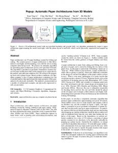
1. INTRODUCTION The technique for making paper was developed by Cai Lun during the Eastern Han Dynasty, 114 AD. After papermaking spread to Europe in the 13th Century, European artists began developing paper sculpture in the mid-18th Century. A planar paper can be transformed into a three-dimensional object via cutting, crimping, folding, and gluing. Origami is a traditional Japanese paper art started in the 17th Century, which was popularized outside Japan in the mid-1900s. An origami architectural is a 3D structure “pops up” from a folded sheet of paper when opened at 90° [1, 2]. The structure is made by cutting and folding paper without gluing or splicing, which is stored by folding the two halves of the paper closed. An origami architectural structure is a type of pop-up card that appears in many forms, such as extremely realistic greeting cards [14]. Figure 1 shows two examples created by Chatani [4]. In China, people send greeting cards during Chinese New Year. Chinese zodiac animals are the most common cards. An origami architectural object is similar to pop-up books, but applies additional constraints to cut and fold patterns on the paper; this is called a planar layout. Some books introduce on the mechanism of designing pop-up crafts [1, 2, 3, 4, 5]. Creating two-dimensional layouts that pop up into a desired 3D object is very difficult,
1
2
DER-LOR WAY, YI-SHAN TSAI AND ZEN-CHUNG SHIH
labor-intensive, and demands a high skill level. The two major topics associated with origami architecture are “building” and “creature” (Fig. 1). Pop-up cards with building object are regular and easy computing the vertical and horizontal features by software tool. Conversely, pop-up cards with animals or flowers are difficult to create because creatures and flowers are having smooth curves. Additionally, origami animals can be more attractive than buildings.
(a) Building pop-up card
(b)Animal pop-up card
Fig. 1: Paper Architectures by Masahiro Chatani.
A number of computer-aided tools have been developed [11, 13, 20, 25]. A user is responsible for deciding where and how cuts and folds should be placed on a piece of paper. Li et al. generated automatic paper architecture from 3D models [22]. Their algorithm performed best when an input model contained mostly horizontal and vertical planes (Fig. 2). However, the resulting bunny model contained large distortions and omitted some important features (Fig. 3). An organic model must express the shape of a creature with a limited number of curves and layers. Buildings generally have a regular structure with clear layering. Unlike buildings structures, creatures are comprised of smooth curves, such that designing a pop-up animal card is more challenging than creating pop-up building cards. This paper provides a novel algorithm that transforms 3D organic models into 2D layers, and applies the 2D layers onto an origami architecture, finally generating the pop-up card layout. The main contributions of this investigation are as follows: (1) This paper presents a directed acyclic graphic (DAG) formulation for planar layouts that can stably pops-up to a paper architecture (2) A novel algorithm is applied for constructing origami architecture following the creation process by an artist. (3) The proposed algorithm generates a foldable layout of origami architecture according to features of an input 3D model. The remainder of this paper is organized as follows. Section 2 reviews work related to origami architecture. Section 3 introduces the design process of the proposed method and the DAG formulation. Sections 4, 5, and 6 describe the process of shape
ORIGAMI POP-UP CARD GENERATION FROM 3D MODELS USING A DIRECTED ACYCLIC GRAPH
3
segmentation, 2D pattern layer conversion and foldable layout generation, respectively. Section 7 demonstrates the effectiveness of the proposed method. Finally, Section 8 gives conclusions and suggests directions for further research.
2. RELATED WORKS Paper Crafting Paper cutting, origami, and strip modeling are paper crafts. Paper cutting, a traditional Chinese art, cuts stylistic patterns using the symmetry of patterns and paper overlapping. Xu developed a simple and efficient algorithm for automatically generating a paper-cutting pattern from a given image [31]. Li extended the 2D paper-cutting scheme into 3D paper cuts, and generated animation with paper cuts in an interactive design [21]. Origami, a traditional Japanese folk art, generates an object by folding paper without damaging the paper. Hull generated an origami method using a piece of paper without cutting or gluing [15]. Folding algorithms and the fold ability of paper have garnered considerable attention in the field of computer geometry [8]. Tachi applied an algorithm that automatically generates arbitrary polyhedral surfaces [29]. For curved folding, which is much more restrictive than conventional origami, Kilian proposed an algorithm that generates curved folds automatically based on an analysis of a developable surface [17]. Paper modeling produces 3D models using developable patches or strips. Mitani developed a method for modeling the surface of a model using strips of paper [26]. Shatz offered a paper crafting algorithm for segmenting a mesh into developable approximations that easy to cut and be glued together [28]. Other methods that use mesh simplification for paper modeling were developed by Garland, Cohen, and Wei [6 , 10, 30]. Paper Architecture Most work on pop-up crafting used a computer-aided environment to design pop-up cards. Matini introduced a computer-aided origami architecture system based on the concept of CAD [25, 26]. Although this system ensures that the output planar layout is foldable, it cannot ensure that the output layout is stable. A similar system is the Popup Workshop for children designed by Hendrix and Eisenberg [13]. Hara et al. considered a 2D version of the pop-up problem and generated an automated solution involving polygonal subdivision [12]. Glassner developed a system that allows users to design V-fold cards interactively [11]. Li et al. developed an interactive tool for designing v-style pop-ups and an automated construction algorithm from a given geometry [23]. Algorithmic solutions for automatically generating pup-up cards have been achieved in recent years. Li et al. designed an algorithm that automatically generates an origami architecture, and ensures that the layout can be erected stably [22]. Figure 2 shows some examples. However, Li’s method only approximates model shape using two directions of patches under origami architecture constraints, and does not work well for organic models that need to retain important features (Fig. 3). Notably, the bunny model contains large distortions and lacks some important features. This paper proposes a novel
4
DER-LOR WAY, YI-SHAN TSAI AND ZEN-CHUNG SHIH
method for creating an origami architecture by considering the characteristics of an organic model.
Fig. 2: Li’s method for architecture.
Fig. 3: Li’s method for non-architecture.
Shape Abstraction Many methods can approximate 3D models for shape abstraction. Segmenting meshes into natural regions is useful for model understanding and shape abstracting applications. Shamir presented a survey of segmentation and partitioning techniques of boundary meshes [27]. They formulated the segmentation problem as an optimization problem and identify two primarily distinct types of mesh segmentation, namely part-type segmentation and surface-type segmentation. In part-type segmentation, the goal is to segment the object represented by the mesh into meaningful, mostly volumetric and parts. Lai used feature sensitive remeshing to produce a hierarchy of meshes, allowing us to efficiently construct a hierarchical segmentation [18, 19]. Figure 4 shows bunny’s examples. Kalogerakis proposed a data-driven approach to simultaneous segmentation and labeling of parts in 3D meshes [16]. Mehra abstracted 3D models by characteristic curves, and reconstructed the abstracted model via these curves using a novel algorithm [24]. Eisemann developed a view-dependent method for converting 3D models into 2D layers [9]. In this paper, the proposed model layering approach considers a viewer’s direction and preserves 2D shape features in the model, such that the origami architecture looks stereo.
ORIGAMI POP-UP CARD GENERATION FROM 3D MODELS USING A DIRECTED ACYCLIC GRAPH
5
Fig. 4: Lai’s feature sensitive mesh segmentation.
3. ALGORITHM FORMULATION Cuts and folds are used to create a paper architecture from a single piece of paper. The planar of the feature shape, such a paper architecture, consists of a folding line and 2D shape patterns that divide the paper into various regions. Typically, two outer regions, called the backdrop and ground, meet at a fold line. Building architecture models have regular shapes and consist of parallel straight lines or planes. The stability of an origami architecture is defined on patches, which may have two directions. However, for organic models consisting of smooth curves and irregular surfaces, such as a creature whose normal direction varies on the surface of 3D object, the approximation result will not be accurate (Fig. 3). Therefore, this work proposes the concepts of layers and connections. The layers are parallel to the backdrop and represent the shape features of 3D models; the connections are parallel to the ground between two layers. To construct pop-up planar layouts, this paper propose a novel algorithm for constructing an origami architecture following the creation process. This paper also offers a DAG for planar layouts that can stably pop-up into a paper architecture. 3.1 Design Process for Origami Architecture Analyzing origami architectures [4], the following steps are used to design origami architecture for organic objects: (1) capture 2D patterns from a 3D object, (2) place the patterns onto layers according to their depths and (3) create connections between layers to generate a foldable layout. The proposed method has three steps: (1) feature shape segmentation, (2) pattern layer conversion and (3) foldable layout generation. Figure 5 shows the design flow of the proposed scheme. First, 2D feature shapes are segmented from a 3D model according to their orthogonal projections (Fig. 5(b)). After computing the depth of layers using a depth map, the positions of layers on the layout are determined (Fig. 5(c)). Connections are then constructed between layers to form an origami architecture, as Fig. 5(d). Finally, the pop-up card is successfully generated according the foldable layout (Fig. 5(e)).
DER-LOR WAY, YI-SHAN TSAI AND ZEN-CHUNG SHIH
6
(a)Bunny Model
(b)Feature Shape
(c)Pattern Layer
(d)Foldable Layout
(e)Pop-up Card
Fig. 5: Designing Process of Origami Architecture.
3.2 Directed Acyclic Graph According to the design process for origami architecture, this paper uses a graph structure to form the planar of the feature shape. After user specified a folding line, Figure 7(a) shows the graph of the Bunny’s feature shape that constructed from Figure 6 by definition 1. Definition 1: Given a graph G(V,E), where V = {v1, v2,…,vn} is a set of vertices and E ⊆ V × V , a vertex vi is a region on the planar paper and an edge e(vi, vj) when they are adjacent neighbor. The crucial goal is to apply computational algorithms to construct planar layouts that can be popped up. To illustrate the algorithm’s design and prove its correctness, this work presents a directed graph for planar layouts, particularly those that can be popped up and are physically realistic. Definition 2: Given a directed graph G(V,E), where V={v1, v2,…,vn} is a set of vertices and E ⊆ V × V ,where e(vi , v j ) ∈ E vertex vj is a successor of vi, that means Layer Li is shallower than Layer Lj.
ORIGAMI POP-UP CARD GENERATION FROM 3D MODELS USING A DIRECTED ACYCLIC GRAPH
7
To construct stable origami architecture, the first task is to construct the hierarchical structure of layers. A stable layer in origami architecture should be supported by a ground or a neighboring layer that is shallower than this layer at contacting points [22, 26]. This work constructs a directed graph corresponding to graph of feature shape (Fig. 7(b)), which records connections between layers. Each directed edge point from node Li to node Lj indicates that Li and Lj are neighboring layers and Li is shallower than Lj. The graph root is ground node G, which represents the shallowest layer, and pseudo backdrop node B represents the deepest layer. Li et al. developed a formal, geometric formulation of planar layouts that pop-up into stable and rigid paper architecture [22]. They discussed the behavior of patches parallel to the backdrop and ground in an origami architecture, and then constructed origami architecture using these patches to approximate the shape of an input model under the stability criterion. If all layers are stable, the origami architecture is stable. According stability rules, the directed graph of a planar layout must be a DAG and meet the following conditions: (1)If a node is connected with both the ground node and backdrop node, it is stable. (2)If a node is connected to the ground node or backdrop node and is connected to a stable node, it is stable. (3)If a node has no fewer than two connections with different stable layers, it is stable.
Fig. 6: Feature Shape
B L1
L2
B L3
L1
L2
L4
L4
G
G
(a)Graph of Feature Shape
L3
(b)Directed Acyclic Graph
Fig. 7: DAG formulation of bunny feature shape.
DER-LOR WAY, YI-SHAN TSAI AND ZEN-CHUNG SHIH
8
Definition 3: A DAG is a directed graph DAG(V,E) with no directed cycles. According to the DAG definition, an edge represents a connection between two layers. The DAG is stable when each node is stable with bread-first traversal node-by-node. For instance, the bunny DAG (Fig. 7(b)), L3 is stable with a connected edge by rule 1; L2 and L4 are stable with a connected edge by rule 2; and L1 is also stable by rule 2.
4. FEATURE SHAPE SEGMENTATION Segmentation and labeling of 3D shapes into meaningful parts is fundamental to shape understanding and processing. Many mesh segmentation techniques are described in section 2. In this paper, the segmentation and labeling of the input model is manually specified. Normally for creature objects are labeled into head, neck, torso, hand (or wing), leg, tail, ... , etc. In order to segment origami architectural layers, each layer has 2D shape features of the object model. Feature shape segmentation is view dependent and separates a labeled model into layers while preserving model features. Figure 8 shows the processing flow of the feature shape segmentation.
(a) Toon Shading and Edge Detection
Labeling (b) Depth Map and Edge Detection Fig. 8: The processing flow of the feature shape segmentation.
First, the model is rendered using toon shading in orthogonal projection with user-specified the direction and position of the light source. Color C of the model is defined as follows: ⎧0, Cs = ⎨ ⎩1,
if
v n ⋅ vl < k
if
v n ⋅ vl ≥ k
(1)
Where vn is the normal of a point on the model surface; vl is the direction of light; and k is the threshold value in the range of 0–1. Image filtering is applied to detect edges of the toon shading result, and the model image is separated into pieces (Fig. 8(a)).
ORIGAMI POP-UP CARD GENERATION FROM 3D MODELS USING A DIRECTED ACYCLIC GRAPH
9
Secondly, this work also detects the depth of map edges, and the depth of map shading will be changed as follows: C’d=clamp(β(α- Cd ), 0,1)
(2)
Where Cd and C’d are the current and new magnitude of a pixel in a depth map respectively, and α and β are parameters that change the depth map shading, α=4.12 and β=0.23 in Fig. 8(b). Then, the image of the input model is separated into segments using toon shading edges, and the erode operation is applied to each segment to remove insignificant pieces. Finally, based on the pre-segmented of labeled 3D model and depth map, each surviving segment is iteratively expanded or merged until segments touch each other or the border of the pre-segmented in labeled model or the detected edge of depth map.
5. PATTERN LAYER CONVERSION For each feature shape segment obtained in Section 4, the depth value of a shape segment is the average of each pixel’s depth value. Depth(Li)=Σ(each pixel’s Depth in Li) / NumberPixels(Li). Let Depth(G)=0 and Depth(B)=1. In order to construct DAG, the direction of e(vi,vj) is determined by depth(vi)