Finally,. Section 6 covers the topic of parallelizing implicit finite element computa- tions on ..... Let us also assume that we can organize the multicomputer in a two- dimensional ...... We remark that being non-periodic in one di- rection means ...
Parallel Computing X. Cai1,2 , E. Acklam3 , H. P. Langtangen1,2 , and A. Tveito1,2 1 2 3
Simula Research Laboratory Department of Informatics, University of Oslo Numerical Objects AS
Abstract. Large-scale parallel computations are more common than ever, due to the increasing availability of multi-processor systems. However, writing parallel software is often a complicated and error-prone task. To relieve Diffpack users of the tedious and low-level technical details of parallel programming, we have designed a set of new software modules, tools, and programming rules, which will be the topic of the present chapter.
1
Introduction to Parallel Computing
Parallel computing, also known as concurrent computing, refers to a group of independent processors working collaboratively to solve a large computational problem. This is motivated by the need to reduce the execution time and to utilize larger memory/storage resources. The essence of parallel computing is to partition and distribute the entire computational work among the involved processors. However, the hardware architecture of any multi-processor computer is quite different from that of a single-processor computer, thus requiring specially adapted parallel software. Although the message passing programming model, especially in terms of the MPI standard [3], promotes a standardized approach to writing parallel programs, it can still be a complicated and error-prone task. To reduce the difficulties, we apply object-oriented programming techniques in creating new software modules, tools, and programming rules, which may greatly decrease the user effort needed in developing parallel code. These issues will be discussed in this chapter within the framework of Diffpack. The contents of this chapter are organized as follows. The present section contains a brief introduction to some important concepts related to parallel computing in general. Section 2 proposes a performance model that has advantages in analyzing and predicting CPU consumptions by complex parallel computations. Then, Section 3 is devoted to an introduction to the basic functionality of the MPI standard. Later on, Section 4 presents a high-level Diffpack interface to the MPI routines, whereas Section 5 concerns parallelizing Diffpack simulators that use explicit finite difference schemes. Finally, Section 6 covers the topic of parallelizing implicit finite element computations on unstructured grids.
2
1.1
X. Cai et al.
Different Hardware Architectures
The hardware architectures of different multiple-processor systems span a wide spectrum. We may categorize multiple-processor systems from the angle of memory configuration. At one extreme, there are the so-called shared memory parallel computers. The most important feature of such parallel computers is that all the processors share a single global memory space, which is realized either at the hardware level or at the software level. At the other extreme of the hardware architecture spectrum, there are the so-called distributed memory parallel computers, where each processor has its own individual memory unit. All the processors are then connected through an interconnection network, by which communication between processors takes place. Using the network speed as a main criterion, we can further divide the distributed memory systems into sub-categories such as high-end massive parallel computers, low-cost PC clusters, networks of workstations, etc. Finally, in the middle of the hardware architecture spectrum, we find distributed shared-memory machines, which are in fact clusters of shared-memory parallel computers. 1.2
The Message-Passing Programming Model
The different types of hardware architecture have their impact on parallel software programming. Two major parallel programming models are thus so-called shared memory and message passing models, which arise from the shared memory and distributed memory hardware architectures, respectively. The shared memory programming model assumes that every process can directly access the global data structure of a parallel program. Each process is implicitly assigned to work on a portion of the global data. Moreover, work load partitioning and inter-process communication are hidden from the user. This programming model is well suited for static and regular data structures, leading normally to parallel execution at the loop level. In the message passing model, however, it is necessary to partition a global problem into several smaller sub-problems and assign them to different processes. Each process has direct access only to its sub-problem data structure. In order for the processes to solve the global problem collaboratively, the user has to insert communication commands in the parallel program. Collaboration between the processes is achieved by explicit message passing, i.e., different processes communicate with each other in form of sending and receiving messages. We remark that message passing enables not only data transfer, but also synchronization, which refers to waiting for the completion of the involved processes, at certain pre-determined points during execution. As the message passing model is more flexible and can also be realized on any shared memory machine, we focus on this programming model. It has been applied in the development of the parallel Diffpack libraries, and will be assumed throughout the rest of this chapter.
Parallel Computing
3
Remark. Strictly speaking, the term process is different from the term processor. A process is an instance of a program executing autonomously, see e.g. [8, Ch. 2.2], whereas a processor is a hardware unit of a computer on which one or several processes can be executed. However, assuming the most common situation where only one process within a parallel computation is executed on one processor, we loosely use these two terms interchangeably in the rest of this chapter. 1.3
A Multicomputer Model
To simplify the description and analysis of the forthcoming parallel algorithms, we adopt the following model of a theoretical multicomputer (see e.g. [11, Ch. 1.2]), which is in fact an idealized model of distributed memory systems. A multicomputer has P identical processors, where every processor has its own memory. Each processor has control of its own local computation, which is carried out sequentially. The processors are interconnected through a communication network, so that any pair of two processors can exchange information in form of sending and receiving messages. Moreover, communication between any two processors is of equal speed, regardless of physical distance. 1.4
Two Examples of Parallel Computing
Addition of Two Vectors. Addition of two vectors is a frequently encountered operation in scientific computing. More precisely, we want to compute w = ax + by, where a and b are two real scalars and the vectors x, y and w are all of length M . In order to carry out the vector addition in parallel, it is necessary to first partition x, y and w among the processors. That is, each processor creates its local storage to hold a portion of every global vector. Using an integer p, which has value between 0 and P − 1, as the processor rank on a P -processor multicomputer, we will have for processor number p: X xp ∈ RMp , yp ∈ RMp , wp ∈ RMp , M = Mp . p
The above partitioning means that for every global index i = 1, 2, . . . , M , there exists an index pair (p, j), 0 ≤ p < P , 1 ≤ j ≤ Mp , such that the correspondence between i and (p, j) is one-to-one. Note that if M = P I for some integer I, a global vector can be divided into P equally sized sub-vectors, each containing I = M/P entries. (For the case where M is not divisible by
4
X. Cai et al.
P , we refer to Section 3.2.) A partitioning scheme that lets each sub-vector contain contiguous entries from the global vector can be as follows: i M , p = b c, j = i − pI . P I Note that we use integer division in the above formula to calculate the p value. Once the partitioning is done, addition of the two vectors can be carried out straightforwardly in parallel by I=
wp = axp + byp ,
p = 0, 1, . . . P − 1 .
Remarks. The partitioning introduced above is non-overlapping in that each entry P of the global vectors x, y and w is assigned to only one processor and M = p Mp . Furthermore, the local vector addition operation can be carried out by each processor, totally independent of other processors. Inner Product of Two Vectors. Unlike the above vector addition operation, most parallel computations require inter-processor communication when being carried out on a multicomputer. An example is the parallel implementation of the inner-product between two vectors. More precisely, we have x ∈ RM and y ∈ RM , and want to compute c=x·y =
M X
xi yi .
i=1
Again, a partitioning of the global vectors x and y needs to precede the parallel inner-product operation. When each processor has the two subvectors ready, we continue with a local computation of the form: cp = xp · yp =
Mp X
xp,j yp,j .
j=1
Then, we can obtain the correct global result by c=
P −1 X
cp ,
(1)
p=0
which can be realized by, e.g., asking every processor to send its local result cp to all the other processors. In this case, the parallel inner-product operation requires an all-to-all inter-processor communication, and we note that the correct global result c will be available on every processor. Remark. An alternative way of realizing (1) will be to designate a so-called master processor, which collects all the local results cp for computing c and then broadcasts the correct global result to all the processors. Consequently, the above all-to-all communication is replaced by first an all-to-one communication and then a one-to-all communication.
Parallel Computing
1.5
5
Performance Modeling
We now study how the execution time of a parallel program depends on the number of processors P . Let us denote by T = T (P ) the execution time for a parallel program when being run on P processors. Performance analysis is to study the properties of T (P ), which mainly consists of two parts: arithmetic time and message exchange time. We remark that the above simple composition of T (P ) is a result of using the multicomputer model from Section 1.3. In the present section, we assume that the global problem size is fixed and thus only study how T depends on P . Assuming also that computation and communication can not be performed simultaneously, we can come up with the following idealized model: T (P ) = max Ip τA + max TCp , 0≤pbroadcast(M); const int P = proc_manager->getNoProcs(); M_p = M/P; r = M % P; // the remaining components will be placed on the last process, so // the remainder variable is set to 0 on all other processes. if (proc_manager->getMyId() < P-1) r = 0; // create the vector segment on this process: Vec(real) vector(M_p + r); // initialize vector (simple formula: vector(i) = 3*i + 2.2) int i,j; for (j = 1; j getMyId() * M_p; // find global index vector(j) = 3*i + 2.2; } // Compute the _square_ of the norm of the local vector segment // (cannot simply add local norms; must add square of norms...) real local_norm2 = sqr(vector.norm()); // or vector.inner(vector) real global_norm2; // let the master process (with rank 0) sum up the local results proc_manager->reduce(local_norm2, global_norm2, PDP_SUM); // let only the master process write the result to the screen: if (proc_manager->master()) { s_o 0, j = 2, . . . , m − 1, k+1 uk+1 1,j = un,j = 0,
j = 1, . . . , m, k ≥ 0,
uk+1 i,1
i = 1, . . . , n, k ≥ 0,
=
uk+1 i,m
= 0,
where ¢ 1 ¡ k ui−1,j − 2uki,j + uki+1,j , 2 ∆x ¢ 1 ¡ k ui,j−1 − 2uki,j + uki,j+1 . ≡ 2 ∆y
[δx δx u]ki,j ≡ [δy δy u]ki,j
Parallel Computing
31
We wish to split the domain Ω into D subdomains Ωs , where s = 1, . . . , D. However, since we now work with two-dimensional, rectangular, finite difference lattice grids, it is convenient to introduce a subdomain numbering using double indices (p, q) in a “Cartesian” grid of P × Q subdomains. When we need to switch between a single index s and the pair (p, q), we assume that there is a mapping µ such that s = µ(p, q) and (p, q) = µ−1 (s). The subdomains can now be defined as follows. q Ωp,q = [xpL , xpR ] × [yB , yTq ] p p xi = xL + (i − 1)∆x, i = 1, . . . , np q yjq = yB + (j − 1)∆y, j = 1, . . . , mq q p p q x1 = xL , xpnp = xpR , y1q = yB , ym = yTq , q Q 1 x1L = 0, xP R = 1, yB = 0, yT = 1 .
Here, we have p = 1, . . . , P , q = 1, . . . , Q and D = P Q. Our numerical scheme has a five-point computational stencil, i.e., for each point, we only need values on points that are one grid cell away. This implies that the optimal overlap between the subdomains is one grid cell. For p = 2, . . . , P − 1 and q = 2, . . . , Q − 1 we then have the relations xp1 = xp−1 np−1 −1 ,
xp2 = xp−1 np−1 ,
xpnp −1 = xp+1 , 1
xpnp = xp+1 , 2
q−1 y1q = ym , q−1 −1
q q−1 y2q = ym , ym = y1q+1 , q−1 q −1
q ym = y2q+1 . q
If either P = 1 or Q = 1 we note that we have a one-dimensional partitioning of the domain. The set of neighboring subdomains Np,q = Nµ−1 (s) is given by Np,q = {(p + 1, q), (p − 1, q), (p, q + 1), (p, q − 1)} . In conformity with the one-dimensional case (Section 5.4), we denote the interpolation operator by I(x, y, t; Np,q ) which interpolates the numerical solution at (x, y, t), where (x, y) is in one of the neighboring subdomains Ωk,l of Ωp,q , i.e., (k, l) ∈ Np,q . The numerical equations for subdomain Ωp,q then read up,q,k+1 = up,q,k + ∆t([δx δx up,q ]ki,j + [δy δy up,q ]ki,j ), i,j i,j up,q,k+1 = I(xp1 , yjq , tk+1 ; Np,q ), 1,j up,q,k+1 np ,j up,q,k+1 i,1 up,q,k+1 i,mq
=
I(xpnp , yjq , tk+1 ; Np,q ),
=
I(xpi , y1q , tk+1 ; Np,q ), q I(xpi , ym , tk+1 ; Np,q ), q
=
i = 2, . . . , np − 1, k > 0, j = 2, . . . , mq − 1,
j = 1, . . . , mq , k > 0, j = 1, . . . , mq , k > 0, i = 1, . . . , np , k > 0, i = 1, . . . , np , k > 0 .
32
X. Cai et al.
For subdomains that border with the physical boundaries, the following updating schemes apply for the points that lie on the physical boundaries: = 0, u1,q,k+1 1,j
j = 1, . . . , mq , k ≥ 0,
uP,q,k+1 nP ,j up,1,k+1 i,1 p,Q,k+1 ui,mQ
= 0,
j = 1, . . . , mq , k ≥ 0,
= 0,
i = 1, . . . , np , k ≥ 0,
= 0,
i = 1, . . . , np , k ≥ 0 .
It is evident that a sequential program solving the global problem can be reused for solving the problem over each subdomain, provided that the domain can be an arbitrary rectangle and that we add functionality for communicating interpolated values between the subdomain solvers. If the subdomains have coinciding grid points, which is the usual case when working with basic finite difference methods, interpolation just means picking out the relevant grid point values from a neighboring subdomain. 5.8
The Sequential Heat Conduction Solver
Following standard Diffpack examples on creating finite difference solvers, see e.g. [6, Ch. 1.7], the heat equation simulator is typically realized as a C++ class with the following content. class Heat2D { protected: Handle(GridLattice) Handle(FieldLattice) Handle(FieldLattice) Handle(TimePrm)
grid; u; u_prev; tip;
// // // //
uniform "finite difference" grid the unknown field to be computed u at the previous time level time step etc.
CPUclock clock; real compute_time;
// for timings within the program
int i0, in, j0, jn; real mu, nu;
// help variables for loops // help variables in the scheme
real initialField (real x, real y );
// initial condition func.
virtual void setIC (); virtual void timeLoop (); void computeInnerPoints (); void computeBoundaryPoints (); void solveAtThisTimeStep (); void updateDataStructures () { *u_prev = *u; } public: Heat2D (); virtual ~Heat2D () {} void scan (GridLattice* grid_ = NULL, TimePrm* tip_ = NULL);
Parallel Computing
33
void solveProblem (); virtual void resultReport (); };
In the above class declaration, we have introduced two non-standard functions computeInnerPoints and computeBoundaryPoints, which separate the computations on inner and boundary points. This is an important split of the implementation of the scheme, because non-blocking communication calls can then be used to hide the cost of communication. Another non-standard feature is that scan can make use of an external grid and external time integration parameters. The particular numerical problem solved by class Heat2D is ∂u ∂2u ∂2u = + 2 ∂t ∂x2 ∂y on the unit square Ω = [0, 1] × [0, 1] with u = 0 on the boundary. The initial condition reads u(x, y, 0) = sin πx sin πy . The computeInnerPoints function typically takes the form void Heat2D:: computeInnerPoints() { int i, j; ArrayGenSel(real)& U = u->values(); ArrayGenSel(real)& Up = u_prev->values(); for (j = j0+2; j values(); for (j = j0+1; j finished()) { tip->increaseTime(); solver->solveAtThisTimeStep(); } }
Finally, the task of collecting the subdomain solutions becomes also simple by calling the ParallelFD::gatherFields function. In other words, we have void ManagerHeat2D :: gatherData (FieldLattice& local_res) { ParallelFD::gatherFields(local_res, *global_res_u); if (proc_manager->master())
Parallel Computing
}
6
37
database->dump (*global_res_u, tip.getPtr());
Parallelizing FE Computations on Unstructured Grids
Finite element methods are often associated with unstructured computational grids. Compared with parallelizing codes for explicit finite difference schemes, see Section 5, the task of parallelizing codes for computation on unstructured grids is more demanding. Many new issues arise, such as general grid partitionings, distribution of unstructured data storage, complex inter-processor communication etc. Parallelizing a sequential finite element simulator from scratch is therefore a complicated and error-prone process. To provide Diffpack users with a straightforward approach to parallelizing their sequential finite element simulators, we have devised an add-on toolbox that hides the cumbersome parallelization specific codes. Instead, the toolbox offers high-level and user-friendly functionality, such that a Diffpack user needs only to insert a few lines of code into his original sequential simulator to transform it into a parallel one. The parallel toolbox ensures that the computation-intensive operations are run in parallel at the linear algebra level. The resulting parallel simulator will maintain the same portability and flexibility as its sequential counterpart. This section gives an introduction to the add-on parallel toolbox. We start with a mathematical explanation of how different linear algebra operations can be parallelized in a divide-and-conquer style. Then, we continue with a brief description of how object-oriented programming enables a seamless coupling between the parallel toolbox and the huge library of existing sequential Diffpack codes. Thereafter, we focus on some of the major functions of the toolbox. Finally, the actual parallelization process is demonstrated by an example, before we give answers to some frequently asked questions about this parallelization approach. We mention that there exists another high-level parallelization approach, which incorporates the mathematical framework of domain decomposition methods. The discussion of this topic will be left to another chapter [1] in this book. 6.1
Parallel Linear Algebra Operations
Let us consider for instance an elliptic boundary value problem discretized on an unstructured finite element grid. Suppose the solution process involves an iterative linear system solver, then the most computation intensive operations viewed at the level of matrices and vectors are: (i) calculation of element matrices and vectors, and (ii) solution of the resulting linear system of equations. Roughly speaking, the parallelization starts with partitioning the global finite element grid into a set of smaller subgrids to be hosted by
38
X. Cai et al.
different processors of a parallel computer. It is important to note that global matrices and vectors need not to be constructed physically. It suffices to deal only with sub-matrices and sub-vectors that are associated with the subgrids. Neighboring processors need to exchange information associated with the nodes that are shared between them. However, the amount of information exchange is rather limited. It will be shown in the following that the linear algebra operations on the original global matrices and vectors can be achieved by operations on the sub-matrices and sub-vectors plus inter-processor communications. We also note that the following parallelization approach and its implementation are only valid for Diffpack finite element simulators using iterative linear system solvers, not direct solvers as e.g. Gaussian elimination. Partitioning Unstructured Finite Element Grids. The essence of parallel computing is to distribute the work load among the processors of a parallel computer. For finite element computations, the work load distribution arises naturally when the entire solution domain is decomposed into a number of subdomains, as a processor only carries out computation restricted to its assigned subdomain. Partitioning a global finite element grid primarily concerns dividing all elements into subgroups. The elements of the global finite element grid M are partitioned to form a set of smaller subgrids SMi , 1 ≤ i ≤ P , where P is typically the number of available processors. By a non-overlapping partitioning, we mean that each element of M is to belong to only one of the subgrids. Element edges shared between neighboring subgrids constitute the so-called internal boundaries. The boundary of a subdomain is either entirely internal or partly internal and partly physical. We note that although every element of M belongs to a single subgrid after a non-overlapping partitioning, the nodes lying on the internal boundaries belong to multiple subgrids at the same time. In Figure 8, the nodes marked with a circle denote such nodes. Ideally, the entire work load should be divided evenly among the available processors. Since the work load of a finite element computation is proportional to the number of elements, the subgrids should have approximately the same number of elements. Due to the necessity of exchange of information associated with the internal boundary nodes, a perfect partitioning scheme should minimize both the number of neighbors and the number of internal boundary nodes for each subgrid. In this way, the communication overhead is minimized. General non-overlapping partitioning of unstructured finite element grids is a non-trivial problem. Here, we only mention that it is often transformed into a graph partitioning problem and solved accordingly, see e.g. [2,12]. Distributed Matrices and Vectors. When a non-overlapping partitioning of the unstructured global finite element grid is ready, one subgrid is to be held by one processor. The discretization of the target partial differential equation on one processor is done in the same way as in the sequential case, only that
Parallel Computing
39
�
�
�
�
�
�
�
�
�
�
�
�
�
�
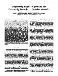
Fig. 8. An example of internal boundary nodes that are shared between neighboring subgrids. The figure shows a small region where three subgrids meet. Elements e1 and e2 belong to one subgrid, e3 and e4 belong to another subgrid, while e5 and e6 belong to a third subgrid. Nodes marked with a circle are internal boundary nodes.
the discretization is restricted to the assigned subdomain. The assembly of the local stiffness matrix and right-hand side vector needs contribution only from all the elements belonging to the current subgrid. So far no inter-processor communication is necessary. Let us denote the number of nodes in subgrid SMi by Ni . For any scalar partial differential equation to be discretized on subgrid SMi , we will come up with a linear system of equations Ai xi = bi , where the local stiffness matrix Ai is of dimension Ni × Ni , and the local right-hand side vector bi and solution vector xi have length Ni . The result of the parallel finite element solution process will be that xi holds the correct solution for all the nodes belonging to SMi . The solution values for the internal boundary nodes are duplicated among neighboring subdomains. In comparison with A and b, which would have arisen from a discretization done on the entire M, entries of Ai and bi that correspond to the interior nodes of SMi are identical with those of A and b. For entries of Ai and bi that correspond to the internal boundary nodes, they are different from those of A and b, because the contributions from the elements that lie in neighboring subgrids are missing. However, this does not prevent us from obtaining the correct result of different linear algebra operations that should have been carried out on the virtual global matrices and vectors. It is achieved by operating solely on local matrices and vectors plus using inter-processor communication, as the following text will show. Three Types of Parallel Linear Algebra Operations. At the linear algebra level, the objective of the parallel solution process is to find the solution of the global system Ax = b through linear algebra operations carried out only on the local systems Ai xi = bi . We emphasize that global matrices
40
X. Cai et al.
and vectors have no physical storage but are represented virtually by local matrices and vectors that are held by the different processors. For iterative solution algorithms, it suffices to parallelize the following three types of global linear algebra operations: 1. Vector addition: w = u + αv, where α is a scalar constant; 2. Inner-product between two vectors: c = u · v; 3. Matrix-vector product: w = Au. Parallel vector addition. Assuming that values of ui and vi on the internal boundary nodes are correctly duplicated between neighboring subdomains, the parallel vector addition wi = ui + αvi is straightforward and needs no inter-processor communication (see Section 1.4). Parallel inner-product between two vectors. The approach from Section PN 1.4 is to be used. However, the result of the local inner-product ci = j i ui,j vi,j can not be added together directly to give the global result, due to the fact that internal boundary nodes are shared between multiple subgrids. Vector entries on those internal boundary nodes must be scaled accordingly. For this purpose, we denote by Oi the set of all the internal boundary nodes of SMi . In addition, each internal boundary node has an integer count ok , k ∈ Oi , which is the total number of subgrids it belongs to, including SMi itself. Then we can get the adjusted local result by X ok − 1 c˜i = ci − ui,k vi,k . ok k∈Oi
Thereafter, the correct result of c = u ·P v can be obtained by collecting all the p adjusted local results in form of c = i c˜i . This is done by inter-processor communication in form of an all-to-all broadcast operation. Parallel matrix-vector product. We recall that a global matrix A does not exist physically, but is represented by a series of local matrices Ai . These local matrices arise from a local assembly process that is restricted to each subdomain. The rows of Ai that correspond to the interior subgrid nodes are correct. A local matrix-vector product wi = Ai ui will thus give correct values of wi for the interior subgrid nodes. However, the rows of Ai that correspond to the internal boundary nodes are only partially correct. For a specific internal boundary node, some of the elements that share this node belong to the neighboring subdomains. The contributions from the element matrices are thus distributed among the neighboring subdomains. Therefore, the correct value in wi for an internal boundary node can only be obtained by adding up contributions from all the neighboring subdomains. For instance, in Figure 8, the nodes with global numbers 3,5,7 need contributions from two neighbors, while the node with global number 1 should add together contributions from all three neighbors. This requires inter-processor communication in form of two and two neighboring subdomains exchanging values on the relevant internal boundary nodes.
Parallel Computing
41
� � � � � � � � � � � � � � �������
����
����
� Non-overlapping partitioning
� � � � � � � ��� � � � � � �������
Overlapping partitioning
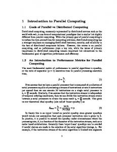
Fig. 9. Extension of a non-overlapping partitioning of a finite element grid into an overlapping partitioning.
Preconditioning and Overlapping Grid Partitioning. Iterative solvers for linear systems often use preconditioners to speed up the convergence. Solving linear systems in parallel requires therefore parallel preconditioning operations. This is an important but tricky issue. We will leave the discussion of parallel multilevel preconditioners such as domain decomposition methods to a later chapter [1], and consider the other Diffpack preconditioners here. It should be pointed out immediately that many preconditioners such as SSOR relaxation and RILU are inherently sequential algorithms. A remedy is to just let each processor run the corresponding localized preconditioning operations, and then take some kind of average of the different values associated with each internal boundary node from neighboring subgrids, see e.g. [9]. However, a different and possibly weakened preconditioning effect may be expected. Careful readers will notice, however, that even the intrinsically parallel Jacobi relaxation does not produce the correct result on a non-overlapping partitioning, because the internal boundary nodes will not be updated correctly. That is, the need for an overlapping partitioning of M arises. More specifically, the non-overlapping subgrids are extended slightly so that every node of M, which does not lie on the physical boundary, is an interior node of at least one subgrid. Figure 9 shows an example of extending a non-overlapping partitioning and making it overlapping. A parallel Jacobi relaxation on an overlapping partitioning will be done as follows: each subdomain runs independently its local Jacobi relaxation, then local results on the internal boundary nodes are discarded and replaced by the correct results sent from the neighboring subdomains, which have those nodes as their interior grid nodes.
42
6.2
X. Cai et al.
Object-Oriented Design of a Parallel Toolbox
It is now clear that at the linear algebra level the global finite element computational operations can be replaced with localized operations plus necessary inter-processor communication. This is good news regarding the parallelization of Diffpack finite element computations, because we can directly utilize the existing sequential codes for carrying out all the local linear algebra operations. Among other things we are able to use the same Diffpack classes for storing the local matrices and vectors, and all the iterative methods for solving linear systems can be used in the same way as before. Of course, new codes need to be written to incorporate two major parallelization specific tasks: general grid partitioning and different forms of inter-processor communication. In this section, we present the design of a small add-on parallel toolbox that contains a number of new C++ classes capable of these two tasks. The add-on toolbox can be coupled seamlessly with the existing huge sequential Diffpack library, thereby allowing Diffpack users to parallelize their finite element computation in a straightforward way. In this connection, object-oriented programming techniques have proved to be successful. Coupling with the Sequential Diffpack Library. One of our objectives is to maintain the comprehensive sequential library of Diffpack independently of the parallel toolbox. The only new class that we have introduced into the sequential Diffpack library is a pure interface class with name SubdCommAdm. The following simplified class definition gives an overview of its most important member functions: class SubdCommAdm : public HandleId { protected: SubdCommAdm () {} public: virtual ~SubdCommAdm () {} virtual void updateGlobalValues (LinEqVector& lvec); virtual void updateInteriorBoundaryNodes (LinEqVector& lvec); virtual void matvec (const LinEqMatrix& Amat, const LinEqVector& c, LinEqVector& d); virtual real innerProd (LinEqVector& x, LinEqVector& y); virtual real norm (Vec(real)& c_vec, Norm_type lp=l2); };
We note that the constructor of class SubdCommAdm is a protected member function, meaning that no instance of SubdCommAdm can be created. In addition, all its member functions, which are virtual, have empty definitions. Therefore, it only serves as a pure interface class defining the name and syntax of different functions for inter-processor communication. Inside the parallel toolbox, we have developed a subclass of SubdCommAdm in order to implement such communication functions. Here, we mention that the member function updateInteriorBoundaryNodes will invoke an inter-processor communication,
Parallel Computing
43
which ensures that all the internal boundary nodes to have correctly duplicated values among neighboring subgrids. In contrast, the updateGlobalValues function concerns overlapping partitionings, i.e., it is meant for all the overlapping nodes shared among neighboring subgrids. Moreover, the member functions matvec, innerProd, and norm are meant to carry out the parallel versions of the matrix-vector product, the inner product between two vectors, and the norm of a vector, respectively. These member functions work for both non-overlapping and overlapping partitionings. It suffices for the rest of the sequential Diffpack library to only know how inter-processor communication can be invoked following the definition of class SubdCommAdm. A few of the linear algebra classes in the sequential Diffpack library were slightly extended to allow a connection with the addon parallel toolbox. The rest of the sequential Diffpack library classes remain intact. For example, class LinEqSystemPrec is now equipped with the following two lines in its definition: Handle(SubdCommAdm) comm_adm; void attachCommAdm (const SubdCommAdm& adm_);
The member function attachCommAdm can be used to set the internal smart pointer comm adm to a concrete object of type SubdCommAdm. Consequently, the member function LinEqSystemPrec::matvec is modified as follows: void LinEqSystemPrec::matvec(const LinEqVector& c, LinEqVector& d) { if (comm_adm.ok()) comm_adm->matvec (*Amat, c, d); // parallel computation else Amat->prod (c, d); // sequential computation matvecCalls++; }
It can be observed that, during a sequential Diffpack simulation, the test if (comm_adm.ok())
should return a false value, so the parallel version of the matrix-vector product will not be invoked. The situation is the opposite during a parallel Diffpack simulation. It is also important to note that these if-tests are hidden from the user and have completely negligible overhead. To relieve Diffpack users of the burden of inserting the attachCommAdm function in many places when parallelizing a sequential Diffpack simulator, the member function LinEqAdm::attachCommAdm makes sure that all the involved linear algebra classes call their respective attachCommAdm functions. So, for the application programmer, one explicit call of LinEqAdm::attachCommAdm is enough before the parallel solution process starts.
44
X. Cai et al.
The Parallel Toolbox. The two main tasks of the toolbox are to provide Diffpack users with different grid partitioning methods and several high-level inter-processor communication functions. In addition, the toolbox also provides parallel versions of some of Diffpack’s most frequently used linear algebra operations. A hierarchy of grid partitioning methods. The purpose of grid partitioning is to provide subdomains with subgrids where local discretization can be carried out. Although the most common situation is to start with a global finite element grid and partition it into smaller subgrids, there can be cases where Diffpack users wish to let each subdomain create its local finite element grid directly either by reading an existing Diffpack GridFE file or meshing the subdomain based on sufficient geometry information. In order to incorporate different grid partitioning approaches, we have created a class hierarchy with a base class named GridPart, whose simplified definition is as follows. class GridPart { public: GridPart (const GridPart_prm& pm); virtual ~GridPart () {} virtual bool makeSubgrids ()=0; virtual bool makeSubgrids (const GridFE& global_grid)=0; };
We can see that GridPart is a so-called pure virtual class in C++, because both versions of the member function makeSubgrids are required to be implemented in a derived subclass. At run time, the real work of grid partitioning is done by one of the makeSubgrids functions in a specific subclass decided by the Diffpack user. The input argument to the constructor is an object of type GridPart prm, which contains diverse grid partition-related parameters. The following subclasses of GridPart are already included in the hierarchy, which also allows a Diffpack user to extend it by developing new subclasses. 1. GridPartUnstruct. This class creates subgrids by partitioning an unstructured global finite element grid. The number of resulting subgrids can be arbitrary and is decided by the user at run time. Class GridPartUnstruct is in fact a pure virtual class itself. Different graph partitioning methods are implemented in different subclasses of GridPartUnstruct. One example is subclass GridPartMetis where the METIS algorithm [5] is implemented. 2. GridPartUniform. This class creates subgrids by a rectangular partitioning of a structured global grid. The subgrids will also be structured so that the user has more control over the partitioning. This simple and flexible partitioning method allows also a 2D or 3D structured global grid to be partitioned in fewer directions than its actual number of spatial dimensions. 3. GridPartFileSource. This class reads ready-made subgrids from Diffpack GridFE data files. All the grid data files should be of the format accepted by the standard Diffpack readOrMakeGrid function.
Parallel Computing
45
The main control class. We recall that SubdCommAdm is a pure interface class; all its inter-processor communication functions need to be implemented in a subclass before they can be used in parallel Diffpack finite element computations. For this purpose, we have created a subclass of SubdCommAdm in the parallel toolbox and named it GridPartAdm. Here, object-oriented programming sets SubdCommAdm as the formal connection between the existing sequential Diffpack library and the parallel toolbox, while GridPartAdm is the actual working unit. It should also be mentioned that class GridPartAdm not only implements the different inter-processor communication functions, but at the same time provides a unified access to the different methods offered by the GridPart hierarchy. In this way, it suffices for a user to only work with GridPartAdm during parallelization of a sequential Diffpack simulator, without making explicit usage of the details of GridPart and GridPart prm etc. A simplified definition of class GridPartAdm is as follows. class GridPartAdm : public SubdCommAdm { protected: Handle(GridPart_prm) param; Handle(GridPart) partitioner; bool overlapping_subgrids; public: GridPartAdm (); virtual ~GridPartAdm (); void copy (const GridPartAdm& adm); static void defineStatic (MenuSystem& menu, int level = MAIN); virtual void scan (MenuSystem& menu); virtual int getNoGlobalSubds() {return param->num_global_subds;} virtual bool overlappingSubgrids(){return overlapping_subgrids;} virtual void prepareSubgrids (); virtual void prepareSubgrids (const GridFE& global_grid); virtual GridFE& getSubgrid (); virtual void prepareCommunication (const DegFreeFE& dof); virtual void updateGlobalValues (LinEqVector& lvec); virtual void updateInteriorBoundaryNodes (LinEqVector& lvec); virtual void matvec (const LinEqMatrix& Amat, const LinEqVector& c, LinEqVector& d); virtual real innerProd (LinEqVector& x, LinEqVector& y); virtual real norm (LinEqVector& lvec, Norm_type lp=l2); };
We can see from above that class GridPartAdm has smart pointers to objects of GridPart prm and GridPart, through which it administers the process of grid partitioning. Inside the GridPartAdm::prepareSubgrids function, an object of GridPart is instantiated to carry out the grid partitioning. The actual type of the grid partitioner is determined at run time according to the user’s input data. We refer to Figure 10 for a schematic diagram describing the relationship between SubdCommAdm, GridPartAdm, and GridPart.
46
X. Cai et al.
SubdCommAdm
GridPartAdm
GridPartUnstructured GridPart
GridPartUniform GridPartFileSource
Fig. 10. The relationship between SubdCommAdm, GridPartAdm, and GridPart. Note that the solid arrows indicate the “is-a” relationship, while the dashed arrows indicates the “has-a” relationship.
6.3
Major Member Functions of GridPartAdm
During parallelization of most sequential Diffpack simulators, an object of GridPartAdm is all a user needs in order to access the desired functionality of the parallel toolbox. We will here give a detailed description of the major functions of GridPartAdm. Grid Partition Related Member Functions. Since there are many parameters associated with the different grid partitioning approaches, the Diffpack MenuSystem class is heavily involved in this process. Thus, almost every parallel Diffpack simulator will need such a statement in its define function: GridPartAdm:: defineStatic (menu, level+1);
Then, typically inside the corresponding scan function, the work of grid partitioning can be carried out as follows: // read information from the input menu gp_adm->scan (menu); // assuming that grid is pointing to the global grid gp_adm->prepareSubgrids (*grid); // now let grid point to the subgrid grid.rebind (gp_adm->getSubgrid());
Here, gp adm is a Handle to a GridPartAdm object. The member function prepareSubgrids has the responsibility of carrying out the grid partitioning, after which the member function getSubgrid will return the reference of the resulting subgrid on every processor. The function prepareSubgrids makes use of different grid parameters that are supplied by the member function pair GridPartAdm::defineStatic and GridPartAdm::scan. In this way, the user
Parallel Computing
47
can make a flexible choice among different grid partitioning methods at run time. The following are examples of parameter input files for three different ways of producing the subgrids: 1. General partitioning of an unstructured global finite element grid: sub set set set ok
GridPart_prm grid source type = GlobalGrid partition-algorithm = METIS number overlaps = 1
The input value GlobalGrid indicates that a global finite element grid is to be partitioned into an arbitrarily given number of subgrids. The number of subgrids is equal to the number of involved processors. For example a run-time command such as mpirun -np 8 ./app
means that eight subgrids will be created, each residing on one processor. The above parameter input file also says that the method of the METIS package will be used to do the general grid partitioning and the resulting non-overlapping partitioning is to be extended to create an overlapping partitioning. 2. User-controlled rectangular partitioning of a uniform grid: sub set set set set ok
GridPart_prm grid source type = UniformPartition subdomain division = d=2 [0,1]x[0,1] [0:4]x[0:2] overlap = [1,1] use triangle elements = ON
The above parameter input file implies that a global 2D uniform mesh, in form of GridFE, will be partitioned into 4 × 2 = 8 uniform local grids. We remark that the redundant geometry information ([0,1]x[0,1]) on the set subdomain division line is ignored by the partitioner. For this example, the parallel finite element application must be started on 8 processors, each taking care of one subdomain. The number of partitions is 4 in the x-direction and 2 in the y-direction. The resulting subgrids will all have 2D triangular elements, and one element overlap layer exists between the neighboring subgrids in both the x- and y-directions. 3. Creation of subgrids directly from grid data files: sub GridPart_prm set grid source type = FileSource set subgrid root name = subd%02d.grid ok
An assumption for using the above input file is that we have a series of grid data files of format GridFE, named subd01.grid, subd02.grid, and so on. Note also that for this grid partitioning approach, we have to use the version of the GridPartAdm::prepareSubgrids function that takes no GridFE input argument. This is because no global finite element grid exists physically. In other words, the work of grid partitioning is done by gp_adm->scan (menu); gp_adm->prepareSubgrids (); grid.rebind (gp_adm->getSubgrid());
48
X. Cai et al.
Communication-Related Member Functions. The communication pattern between neighboring subgrids that arise from a general grid partitioning is complex. However, for a fixed partitioning, whether overlapping or not, the communication pattern is fixed throughout the computation. The member function prepareCommunication thus has the responsibility of finding out the communication pattern before the parallel computation starts. One example of invoking the function is gp_adm->prepareCommunication (*dof);
where dof is a Handle to a DegFreeFE object. That is, the function takes a Diffpack DegFreeFE object as the input argument. For each subdomain, this function finds out all its neighboring subdomains. Additionally, the function also finds out how to exchange information between each pair of neighboring subdomains. The storage allocation for the outgoing and incoming messages is also done in prepareCommunication. After that, the member function attachCommAdm belonging to class LinEqAdm should be called such as: lineq->attachCommAdm (*gp_adm);
The design of the parallel toolbox has made the parallelization process extremely simple for the user. The above statement is sufficient for ensuring that necessary inter-processor communication will be carried out by the standard Diffpack libraries when solving the linear systems of equations. However, in certain cases a user needs to explicitly invoke one of the two following functions of GridPartAdm for inter-processor communication. updateGlobalValues ensures that all the nodes that are shared between mul-
tiple subgrids have correctly duplicated values. For non-overlapping grid partitionings, this means that for a particular internal boundary node, the different values coming from the neighboring subgrids are collected and summed up. For overlapping grid partitionings, every internal boundary node throws away its current value and replaces it with a value provided by a neighboring subgrid, which has an interior node with the same coordinates. If an internal boundary node lies in the interior of more than one neighboring subgrid, an average of the values, which are provided by these neighboring subgrids, becomes the new value. updateInteriorBoundaryNodes has the same effect for non-overlapping grid partitionings as updateGlobalValues. For overlapping grid partitionings, the function only applies to the internal boundary nodes, whereas values of the other nodes in the overlapping regions are unaffected. The member functions matvec, innerProd, and norm of class GridPartAdm can be used to carry out the parallel version of respectively matrix-vector product, inner product between two vectors, and norm of a vector. Inside these functions, local linear algebra operations are carried out by invoking the corresponding sequential Diffpack functions before some inter-processor communication, see also Section 6.2.
Parallel Computing
6.4
49
A Parallelization Example
We consider a standard sequential Diffpack finite element simulator Poisson1 from [6]. The parallelization is quite straightforward, so it is sufficient to insert parallelization specific codes directly into the original sequential simulator, enclosed in the preprocessor directive #ifdef DP_PARALLEL_LA ... #endif
In this way, we will be able to maintain a single code for both the sequential and parallel simulators. The first thing to do is to insert the following line in the beginning of the header file: #ifdef DP_PARALLEL_LA #include #endif
The next thing to do is to include a handle of a GridPartAdm object in the definition of class Poisson1, i.e., #ifdef DP_PARALLEL_LA Handle(GridPartAdm) gp_adm; #endif
Thereafter, three modifications remain to be done in the original sequential code. The first modification is to put inside the define function the following line: #ifdef DP_PARALLEL_LA GridPartAdm::defineStatic (menu,level+1); #endif
The second code modification is to let the GridPartAdm object produce the subgrid, i.e., inside the scan function: #ifdef DP_PARALLEL_LA gp_adm.rebind (new GridPartAdm); gp_adm->scan (menu); gp_adm->prepareSubgrids (*grid); grid.rebind (gp_adm->getSubgrid()); #endif
The third required code modification is to add the following two lines of new code, after the LinEqAdmFE object is created and its scan is called: #ifdef DP_PARALLEL_LA gp_adm->prepareCommunication (*dof); lineq->attachCommAdm (*gp_adm); #endif
50
X. Cai et al.
Here, the first of the above two new code lines invokes the member function GridPartAdm::prepareCommunication, which must precede all the subsequent inter-processor communications. The second line attaches the GridPartAdm object to lineq, which points to a Diffpack LinEqAdmFE object. As mentioned earlier in Section 6.2, the LinEqAdmFE object will then automatically invoke all the other needed attachCommAdm functions, including e.g. the one belonging to LinEqSystemPrec. In this way, necessary communication and synchronization will be enforced during the solution process later. The final task is to insert initDpParallelLA (nargs, args);
as the first statement in the main program and insert closeDpParallelLA();
at the end. 6.5
Storage of Computation Results and Visualization
The storage of computation results during a parallel Diffpack simulation can be carried out exactly as before, e.g. through the usage of SaveSimRes. The only exceptions are the use of SaveSimRes::lineCurves and time series plot for a given spatial point. These should be avoided in a parallel Diffpack simulator. For each processor involved in a parallel Diffpack simulation, the global casename variable will be automatically suffixed with p0000, p0001, . . . , for respectively processor number one, number two, and so on. That is, each processor has a unique casename variable and therefore operates with its own SimResFile. In multiple-loop computations, the processor rank is added in front of the multiple-loop identification number, like p0000 m01, p0001 m01. Four Useful Tools. As explained above, each processor generates its own SimResFile during a parallel simulation. When the parallel simulation is done, the user will face a series of SimResFile databases, possibly after collecting them from different hard disks. To visualize such parallel simulation results, using e.g. Vtk, it is necessary to run the simres2vtk filter for each of the SimResFiles. In order to relieve the user’s effort of having to filter all the SimResFiles one by one, we have devised a tool named distrsimres. This is a Perl script that automatically visits all the SimResFiles. An example of using distrsimres can e.g. be: distrsimres simres2vtk -f SIMULATION -E -a
That is, the user just needs to prefix any simres2xxx command with the distrsimres script. Similarly, for a multiple-loop simulation, it is necessary to add the loop-number specification to the casename, like e.g. distrsimres simres2vtk -f SIMULATION_m02 -E -a
Parallel Computing
51
The second tool is another Perl script with name distrsummary. It can be used to generate a single HTML summary file that contains links to all the casename p00xx-summary.html files, which will be generated by a parallel simulation that uses Diffpack’s automatic report generation functionality. The syntax is simply distrsummary -f casename
The third tool is a compiled Diffpack application, named distr2glob, which can be used to “patch together” chosen field(s) that are stored distributedly in the different SimResFiles. To use distr2glob, the user specifies a global grid, typically a quite coarse grid of type GridLattice. Then distr2glob maps the distributed SimResFile data onto the specified global coarse grid. The result is a new SimResFile that contains the chosen field(s) on the global coarse grid. An example execution of distr2glob can be distr2glob -gg coarse.grid -const 0 -f SIMULATION -r 1 -s -a
The effect is that the first scalar field (due to the -r option), which is stored distributedly in the different SimResFiles that share the root casename SIMULATION (due to the -f option), is mapped onto a global coarse grid given by the grid file coarse.grid (due to the -gg option) and stored eventually in a new SimResFile. In short, the user can use most of the options available for a standard simres2xxx filter, such as -r, -t, -A, and -E, to choose wanted subdomain field(s). In addition, the new option -gg takes a text string of the format acceptable by Diffpack’s readOrMakeGrid command and the other new option -const reads a default value to be assigned to those grid points of the global coarse grid lying outside the original global solution domain. The fourth tool is a new version of RmCase for parallel simulations. By specifying the value of casename such as SIMULATION or SIMULATION m01, the user can remove all the files related to casename. A Simple GUI for Visualization. We have mentioned that the distr2glob tool can allow the user to rapidly check the parallel data set against a global coarse grid. However, for more detailed visualization of the parallel computation results, we have created a new Perl script similar to vtkviz. The new Perl script is named distrvtkviz and its work is to run vtk with an input VtkTcl script named ParaViewer.tcl. We recall that the work of vtkviz is to run vtk with Examiner.tcl as input. The new features of ParaViewer.tcl are that the user can freely add/remove sub-grid data set(s) and concentrate on a particular sub-grid, if desired. To use distrvtkviz, the only thing a user needs to do is to run the distrsimres simres2vtk command, before starting the GUI by issuing the command distrvtkviz
52
6.6
X. Cai et al.
Questions and Answers
1. When should I use a non-overlapping partitioning of an unstructured finite element grid, when to use an overlapping partitioning? In principle, using an overlapping partitioning is always a safe approach in that parallelization of certain operations can not achieve correct result on a non-overlapping partitioning. An example is parallel Jacobi relaxation. However, an overlapping partitioning results in more computation per processor. So it is advantageous to first check whether the two different partitions produce the same result on a coarse global finite element grid before running full-scaled simulations in parallel. 2. How do I produce a 2D partitioning of a 3D uniform finite element grid? Assume that a 100 × 100 × 100 uniform mesh covering the unit cube is desired to be partitioned into 10 subgrids. The number of partitions in the x−, y−, and z−directions are 5, 2, 1, respectively. In addition, one layer of element overlap is desired between the neighboring subgrids. Then the following information can be used in the input parameter file: sub set set set ok
GridPart_prm grid source type = UniformPartition subdomain division =d=3 [0,1]x[0,1]x[0,1] [0:5]x[0:2]x[0:1] overlap = [1,1,0]
3. When should I use GridPartAdm::updateGlobalValues? For non-overlapping partitionings, the two functions updateGlobalValues and updateInteriorBoundaryNodes of class GridPartAdm have exactly the same effect. For overlapping partitionings, some situations only require that internal boundary nodes of a subgrid should receive their correct values from neighboring subgrids, where those nodes are interior subgrid nodes. More precisely, the functionality of updateInteriorBoundaryNodes is a subset of that of updateGlobalValues. So updateGlobalValues is always safe to use but may introduce some unnecessary communication overhead. 4. What do I do when I want to work with both scalar and vector fields in my Diffpack simulator? Assume that all the scalar fields use one DegFreeFE object and all the vector fields use another DegFreeFE object, while the two DegFreeFE objects share the same GridFE object. In this situation, two objects of type GridPartAdm are needed, one for all the scalar fields, the other for all the vector fields. Since all the fields need to work on the same partitioning of the global finite element grid, only one GridPartAdm will have the responsibility of doing the grid partitioning, whereas the other GridPartAdm copies the partitioning. Handle(GridPartAdm) adm1, adm2; Handle(GridFE) grid; Handle(DegFreeFE) dof1, dof2; Handle(LinEqAdm) lineq1, lineq2; // .... adm1->scan (menu); adm1->prepareSubgrids ();
Parallel Computing
53
grid.rebind (adm1->getSubgrid()); // ... adm1->prepareCommunication (*dof1); lineq1->attachCommdm (*adm1); adm2->copy (*adm1); adm2->prepareCommunication (*dof2); lineq2->attachCommdm (*adm2);
5. How do I parallelize a nonlinear PDE solver? Carry out all the above steps, and invoke in addition: nlsolver->attachCommAdm (*gp_adm);
6. Is it possible to parallelize explicit FE schemes? Yes. Let us look at $NOR/doc/Book/src/fem/Wave1 for instance (see [6]). The main simulator class Wave1 does not use LinEqAdmFE, but uses Gaussian elimination to solve the diagonal mass matrix M at each time level. Because the entries of M associated with the internal boundary nodes are not correct, we need the following modification of M for each subgrid, once and for all: for (i=1; iupdateInteriorBoundaryNodes (scratch); for (i=1; ivalues()); // scratch = K*u^0 gp_adm->updateInteriorBoundaryNodes (scratch); 7. Are there any functions of SaveSimRes that can not be used in parallel
simulations? The use of SaveSimRes::lineCurves and time series plot for a given spatial point should be avoided in parallel Diffpack simulations. 8. How do I avoid unnecessary output from every processor? Use the following if-test before e.g. an output statement to s o: if (proc_manager->master()) s_o time(), *error); DistrErrorNorms::Lnorm // fills the error norms (*gp_adm, *uanal, *u, tip->time(), L1_error, L2_error, Linf_error, error_itg_pt_tp);
10. How do I find the global maximum value of a scalar field? The basic idea is to first find the local maximum value and then use the functionality offered by DistrProcManager to find the global maximum value.
54
X. Cai et al. real global_max, local_max = sub_field.values().maxValue(); proc_manager->allReduce(local_max,global_max,PDP_MAX);
11. Is it possible to solve a global linear system in parallel by Gaussian Elimination? No, this is not possible for the current version of the parallel toolbox. Only parallel iterative solvers are supported. As the default answer to the basic method item in a LinEqSolver prm sub-menu is GaussElim, the user has to specifically write, e.g., set basic method = ConjGrad
in an input file to the Diffpack MenuSystem.
References 1. X. Cai. Overlapping domain decomposition methods. In H. P. Langtangen and A. Tveito, editors, Advanced Topics in Computational Partial Differential Equations – Numerical Methods and Diffpack Programming. Springer, 2003. 2. C. Farhat and M. Lesoinne. Automatic partitioning of unstructured meshes for the parallel solution of problems in computational mechanics. Internat. J. Numer. Meth. Engrg., 36:745–764, 1993. 3. Message Passing Interface Forum. MPI: A message-passing interface standard. Internat. J. Supercomputer Appl., 8:159–416, 1994. 4. I. Foster. Designing and Building Parallel Programs. Addison-Wesley, 1995. 5. G. Karypis and V. Kumar. Metis: Unstructured graph partitioning and sparse matrix ordering system. Technical report, Department of Computer Science, University of Minnesota, Minneapolis/St. Paul, MN, 1995. 6. H. P. Langtangen. Computational Partial Differential Equations - Numerical Methods and Diffpack Programming. Textbooks in Computational Science and Engineering. Springer, 2nd edition, 2003. 7. D.J. Lilja. Measuring Computer Performance – A Pratitioner’s Guide. Cambridge University Press, 2000. 8. P.S. Pacheco. Parallel Programming with MPI. Morgan Kaufmann Publishers, 1997. 9. G. Radicati and Y. Robert. Parallel conjuget gradient-like algorithms for solving sparse nonsymmetric linear systems on a vector multiprocessor. Parallel Computing, 11:223–239, 1989. 10. V. Sunderam. PVM: A framework for parallel distributed computing. Concurrency: Practice and Experience, 2:315–339, 1990. 11. E.F. Van de Velde. Concurrent Scientific Computing. Springer-Verlag, 1994. 12. D. Vanderstraeten and R. Keunings. Optimized partitioning of unstructured finite element meshes. Internat. J. Numer. Meth. Engrg., 38:433–450, 1995.