dem Fachbereich Mathematik/Inforinatik der Universit,ä Bremen vorgelegt wurde. Sie ist in elektronischer Form erhältlic unter http : //elib . suub . uni-bremen.
Parallel Filter Algorithms for Data Assimilation in Oceanography Parallele Filteralgorithmen zur Datenassimilation in der Ozeanographie Lars Nerger
Ber. Polarforsch. Meeresforsch. 487 (2004) ISSN 1618 3193
-
Lars Nerger Alfred-Wegener-Institut füPolar- und Meeresforschung Postfach 120161. D-27515 Bremerhaven. Germany 1nergerQawi-breinerhaven.de
Die vorliegende Arbeit ist die inhaltlich unverändert Fassung einer Dissertation, zur Erlangung des Doktorgrades der Naturwissenscha,ften, die im Dezember 2003 dem Fachbereich Mathematik/Inforinatik der Universit,äBremen vorgelegt wurde. Sie ist in elektronischer Form erhältlic unter h t t p : //elib . suub .uni-bremen. de/.
Contents Kurzfassung
V
Abstract
vi
Introduction
I
1
Error Subspace Kaiman Filters
5
1 Data Assimilation 7 . . . . . . . . . . . . . . . . . . . . . . . . . . . . . . . . . . 1.1 Overview 7 1.2 The Adjoint Method . . . . . . . . . . . . . . . . . . . . . . . . . . . 8 1.3 Sequential Data. Assimila.tion . . . . . . . . . . . . . . . . . . . . . . . 11
2 Filter Algorithms 12 2.1 Introduction . . . . . . . . . . . . . . . . . . . . . . . . . . . . . . . .12 2.2 Statistical Estimation . . . . . . . . . . . . . . . . . . . . . . . . . . . 12 2.3 The Extended Kalma.n Filter . . . . . . . . . . . . . . . . . . . . . . . 14 2.4 Error subspace Kaiman Filters . . . . . . . . . . . . . . . . . . . . . . 17 2.4.1 SEEK - The Singular Evolutive Extended I. The time evolution of t,he state is described by the model
.
with the initial condition
x ( t o ) = XQ .
(1.2)
In addit,ion. observations { y o ( t z ) }of the state will be available a t some time instances {tz, i == 1 , .. . , k } . Let the misfit between t,he state and the observations be described by the scalar cost functional J given by
where u is the vector of control variables. For simplicity we consider the case that tlie initial st,ate is used as t-he control variables:
The problem of varia,tional data assiinilation is now: Find t h e optimal vector of control variables which niinimizes the cost f~inctionalJ :
U
To n~inimizeJ with respect t o U, e.g. by the quasi-Newton optimization method, the gradient VuJ has to be computed. The gradient is definecl by
1.2 The A d j o i n t M e t h o d
9
where & J is the first order variation of J with respect to U . 6 u is the perturbation of U . From equation (1.3) the first order variation of J resulting from a perturbation 6 x ( t o ) is given by
) } related to the perturbation 6 x ( t o ) by where the first order variations { & X ( < : ,are
R(tz,to)is the resolvent of the linearization
of equation (1.1) about the state x ( t ) . Here M ( t ) is the linearized model operator. Equation (1.9) is also denoted the tangent linear model. The resolvent R(ti. t o ) is the linear operator obt,ained by integrating equation (1.9) from time to to time tz under the initial condition 6 x ( t o ) = d u . For any continuous linear operator L 011 S exists a linea,r operator L' on S defined by a ,~b>= see Golub and van Loan [26]. The retained principal vectors {G('), i = 1,. . . ,r}
2.4 Error subsoace Kaiman Filters
18
Figure 2.1: Probability ellipsoid representing the probability density function p(xf).
are the basis vectors of a tangent space at the state space point X;. This is the en-or subspace £which approximates the true error space characterized by t h e full covariance matrix. The metric of 2 is given by G = diag ( ( A ^ ) l , . . . , ( A M ) ' ) . In SEEK the error subspace is evolved until the next analysis time of the filter by forecasting the vectors {V('), i = 1,.. . , r} with the linearized model. In the analysis phase the filter operates only in the error subspace, t,hat is, in the most significant directions of uncertainty. The SEEK filter is given by the following eqmtions: Initialization: The initial probability density p(x6) is provided by the initial state estimate xg and a rank-r a.pproximation (T ; P;:=V~U~V~~P; (2.24)
W X rcontains in its columns the corresponding eigenvectors Here, Matrix V. (modes) of P;. The diagonal n~atrixU. ? W^ holds the r largest eigenvalues. Forecast : The SEEK forecast equa,tions are derived from the EKF by treating the covariance matrix in decomposed form as provided by the initialization.
Analysis: The analysis equations are a re-formulation of the EKF analysis equations for a covariance matrix given in decomposed form. To maintain the rank r of P?j the model error covariance matrix Qk is projected onto the error subspace by
With this the SEEK 3nalysis equations are for an invertible matrix
Rk
2.4 Error subsuace Kaiman Filters
19
The analysis covariance matrix is implicitly given by P?,:= Vt.UkV^. Re-diagonalization: To avoid that the modes {V/,)} become large and increasingly aligned a re-orthonormalization of these vectors is required. This ca,n be performed by computing the eigenvalue decomposition of thc matrix B;, 6 Rrxrdefined by
where A k is computed by a Cholesky decomposition of the matrix U k : U k = A k A z . The eigenvalues of B k are the Same as the non-zero eigenvalues of P? = V ~ U ; , V ~ . Let C k contain in its coluinns the eigenvectors of B k and the diagonal matrix D\-the corresponding eigenvalues. Then the matrix V holding re-orthonormalized modes and the corresponding eigenvalue matrix U are given by
Remark 11: The sta,te covariance matrix is a p p r ~ x i m ~ t eby d a singular matrix P of low rank. Throughout the algorithm the approximated matrix is treated in the decomposed form P = V U V T . The full covariance matrix is never computed explicitly a,nd has never to be stored. Remark 12: Due to its treatment in decomposed form. all operations on P are performed symmetrically. Hence, P remains symmetric throughout the algorithm. Remark 13: It is not required that the decomposition of P is computed frorn a truncated eigenvalue decomposition of the prescribed matrix Pi. However, mathematically this yields the best approximation of Pi. Remark 14: The forecast of the covariance matrix is computed by only forecasting the r modes of P. With typically r < 100 this brings this forecast toward acceptable computation times. Remark 15: The SEEK filter is a re-formulation of the EKF focusing on the analyzed state estimate and covaria,nce matrix. Hence its filtering performance will be sub-optimal. Further. SEEK inherits the stability problem of the EKF by considering only the two lowest statistical moments of the probability density. If r is too small, this problem is even amplified. as Pa systematically underestimates the varia,nce prescribed by the full covariance matrix Pa. This is due t o the neglect of eigenvalues of the positive semi-definite matrix Pa. Remark 16: The increment for the analysis update of the state estimate in equation (2.29) is computed as a weighted average of the mode vectors in. V\- which belong to the error subspace. This becomes visible when the definition of the Kaiman gain (equation (2.30)) is inserted into equation (2.29):
The term in bra,ckets represents a vector of weights for combining the modes V . Remark 17: In practice, it can be difficult to specify the linearized dynamic model operator Mi,;_i. As an alternative, one ca,n approximate the linearization by a gradient approximation. Then, the forecast of column a of V:, denoted by V", is given by
20
2.4 Error subspace Kaiman Filters
For a gradient approximation the coefficient e needs to be a small positive numbei- (e < 1). Some authors [91, 311 report the use of e w 1. This can bring the algorithm beyond a. purely tangent-linear forecast but it is no more defined as a . gradient a.pproximation and requires an ensemble interpretation. Remark 18: Due the neglect of higher order terms in the Taylor expansion (2.20) the forecast of the stak estimate will be systematically biased. To account for the first neglected term in the Taylor expansion second order forecast schemes have been discussed [87, 731. The examination of the forecast bias can also be utilized to quantify the nonlinearity of the forecast [89]. Remark 19: Equation (2.28) for the matrix Uk can be modified by multiplying with a so called forgetting factor p, (0 < p 1) [68]:
> m, this alternative variant performs less floating point operations than the variant shown above for 2m < N.
3.3.3
The Resampling Phase
The resampling phases of SEEK and SEIK are independent from model or observa,tions. The implementation of the resampling algorithms is shown as algorithm 3.7 for the SEEK and 3.8 for the SEIK algorithm. For SEEK the algorithm t o re-orthonormalize the modes of the covaria,nce matrix is implemented by first computing the product V T V . This is rather costly operation requiring n,r2 operations. The other products to complete the computation of B are only 0 ( r 3 ) . The resampling of the ensemble in SEIK (equation 2.71) involves again the matrix L. As in the analysis algorithm, we do not compute this matrix explicitly. Instead, matrix T is applied from the left t o the maE This operation is analogous to the operation Ta which trix was discussed for the analysis algorithm of SEIK. Since the application of T from the left acts on columns, the operation in the remmpling corresponds t o the application to N vectors. Thus, the application of T t o a matrix is the generalization of the application t o a. vector.
3.3 I m p l e m e n t a t i o n
44
S u b r o u t i n e EnKF_Analysis(step,n,N,X)
1: 2:
3: 23: 24:
call Get_Dim_Obs(step,m) {get observation dimension, user supplied} Allocate fields: T l ( m , Al), t 2 ( m ) , T 3 ( m 1m), t 4 ( m ) , T 5 ( n , N), T 6 ( n , m ) , B(m,,N},D(m,N),x(n) T6
X
5 T l T {with BLAS routine DGEMM} X + ( N - 1 ) - I T 6 B {with BLAS routine DGEMM}
+T
+
Algorithm 3.6: Variant OS the filter analysis routine for the EnKF algorithm using the represented update variant for a non-singular matrix T3. This variant will yield better performance if there are significantly less observations then ensemble members. If n S> m, this limit is at 2m < N.
S u b r o u t i n e SEEK-Reortho(n,r,Uinv,V) int n {state dimension, input} int r {rank of covariance matrix, input} real Uinv(r, r ) {inverse eigenvalue matrix, iuput/output} real V ( n , r ) {mode matrix, input/output} real T l , T 2 , T3, T 4 , A , B, C , D, L, U {local fields to be allocated} I:
2: 3:
4: 5: 6: 7: 8: 9: 10:
11: 12: 13:
Allocate fields: Tl(r,r ) ,T 2 ( r , r ) , T 3 ( r , r ) ,T 4 ( r , r ) ,
A(r,r),B(r,r),C(r,r),D(r,r),L(n,,r),U(r,r) U + u i n v - l {inversion using LAPACK routine DGESV} Cholesky decomposition: U = AAT {using LAPACK routine DPOTRF} T l + V T V {with BLAS routine DGEMM} T 2 + T l A {with BLAS routine DGEMM} B + AT T 2 {with BLAS routine DGEMM} SVD: B = C D C T {using LAPACK routine DSYEV} T 3 + C D-1/2 T 4 + A T 3 {with BLAS routine DGEMM} L + V V + L T 4 {with BLAS routine DGEMM} U i n v ^- D-1 De-allocate local analysis fields
14: IAlgorithm 3.7: Structure of the re-orthonormalization routine for the SEEK algorithm. The matrix D holding the singular values of B is introduced here for clarity. In the program it is allocated as a vector holding the eigenvalues of B. Matrices A , T l , C, T3, and T4 are not allocated in the program. Their information is stored in other arrays.
3.3 Imvlementation
45
Subroutine SEIK_Resample(n,N,x,Uinv,X) int n {state dimension, input} int N {ensemble size, input} real x ( n ) {sta,te a,nalysis vector, input} real Uinv(r, r ) {inverse eigenvalue matrix, input} real X ( n , Ar) {ensemble ma,trix input/output } real T l , T 2 , T 3 , O T ,C {local fields to be allocated} int r {rank of covariance matrix, r = N - 1) Alloca,te local analysis fields: T l ( r , N ) , T 2 ( N , N), T 3 ( n , AT), ^(T, N ) , C ( r ,r; Cholesky decomposition: Uinv = C CT {using LAPACK routine DPOTRF} initialize OT {implemented as a subroutine} solve C T T l = OT for T l {using LAPACK routine DTRTRS} T2 t- T T l {implemented with T as operator} for i=l.N do T3(:, z) +- X(:, i) X(:, 2) t- X
end for X t- X + NI''
T3 T 2 {with BLAS routine DGEMM} De-allocate local a,nalysis fields
Algorithm 3.8: Structure of the re-orthonormalization routine for the SEEK algorithm. The matrices C arid T l are introduced here for clarity. In the program they are not allocated as their information is stored respectively in Uinv and OT.
Subroutine SEEK-Reortho_Block(n,r,Uinv,V) int maxblksize {Maximum size for blocking} int blklower, blkupper {Counters for blocking} 1:
11: 12: 13: 14: 15:
Allocate fields: . . . , Ldblkmax, r)
for i = 1,n , maxblksize do
+ +
blkupper + min(blk1ower maxblksize - 1;n) Lb(1 : blkupper - blklower 1,:) t- V(blk1ower : blkupper, :) V(b1klower : blkupper, :) + Lb(1 : blkupper - blklower 1, :) T 4
+
end for
Algorithm 3.9: Block formulation for the part of the re-orthonormalization routine of SEEK which initializes the new covariance modes. The block formulation replaces lines 11 and 12 of algorithm 3.7. The lower index b denotes that only a block of size maxblkszze X r of the matnx L is allocated.
3.4 Computational Complexity of the Algorithms
3.3.4
46
Optimizations for Efficiency
The analysis and resampling phases contain several matrix-matrix and matrix-vector products. The sequences chosen for the computation of the products minimizes the size of the arrays to be allocated. For efficiency we implement the products using the highly optimized BLAS libra,ry routines. Other operations, like the Cholesky factorization in the resampling phase of SEIK, the eigenvalue decompositions, or the Inversion of U 1 in the analysis phases of SEEK and SEIK 're implemented using LAPACK library routines. The use of library functions is documented in the annotations in the algorithms 3.3 to 3.8. All three analysis algorithms and both resampling algorithms allow for a block formulation of the final ma,trix-matrix product updating the ensemble or mode matrix. In some situations this can reduce the memory requirements of the algorithms and may lead to a better performance of the algorithms (if the BLAS routine itself does not use a blocking internally). In the context of the EnKF a block formulation has been discussed by Evensen [18].To exemplify the block formulation we consider the resampling algorithm of SEEK. The variant without blocking is shown as algorithm 3.7 while the variant with blocking is displayed as algorithm 3.9. For the block algorithm a loop is constructed running from 1 to n with a step size of the chosen blocking size maxbiksize. Within the loop, rnatrix L is 'llocated as a. matrix Lb with only maxbiksize rows. The loop counter determines which rows of V are updated in a single cycle. In each loop cycle only the corresponding rows of L are initialized in Lb and used to update the selected rows of V. With the block formulation the required memory allocation for L can be significantly reduced from n X r to maxbiksize X r , where m,axblksize w 100,. . . ,500. In addition, the performance of the algorithm may be higher with the block formulation, since the smaller matrices may better fit into the caches of the processor. This would reduce costly tra,nsfers between the caches and the main memory of the computer.
3.4
Computational Complexity of the Algorithms
In most realistic filtering applications the major amount of computing time is spent for the model evolution. This time is proportional t o the size of the ensemble to be evolved. It is equal for all three algorithms if r + 1 = Ar where r is the rank of the approximated covariance matrix in SEEK and SEIK and N is the ensemble size in EnKF. For efficient data assimilation it is thus of highest interest t o find the algorithm which yields the best filtering performance, in terms of estimation error reduction. with the smallest ensemble size. The forecast phase consists of N independent model evaluations. This is also true for the SEEK filter if a gradient approximation of the linearized model is used. Distributing the model evaluations over multiple processors would permit t o compute several model forecasts concurrently. Thus. the independence of the model forecasts can be utilized by parallelization. We will examine this possibility in detail in part 2 of this work. The computation time spent in the analysis and remmpling phases can also be non-negligible. especially if observations are frequently available. The three filter algorithms can show significant differences in these phases. Below we assume n >> m > N . This situation occurs if we have a la,rge scale model. Also m can be significantly larger than N , e.g., if data from satellite altimetry is used. Under
3.4 Computational Complexity of the Algorithms
47
this assumptions operations on arrays involving the dimension n are most expensive followed by operations on arrays involving the dimension m. Table 3.1 shows the scaling of the computational complexity for the three filter algorithms. Since we are only interested in the scaling, we neglect in tlie table the difference between r and N. We use N if somc operation is proportional to the ensemble size of the rank of the covariance matrix. Without the explicit treatment of the model error covariance matrix Q the SEEK filter is the most efficient algorithm. All operations which depend on the state dimension n scale linear with n. These operations occur in the update of the stat,e estimate in line 13 of algorithm 3.3. The matrix of weights for tlie state update is computed in the error space. Thus. the complexity of several operations depends on N . Most costly is the solver step in line 12 which scales with U(N3). The product R I H V , which is required in the update of U 1 in equation (2.28), is the only operation which can be proportional to O(m2N). The full cost will only occur if different measurements are correlated. If the measurements are independent, the observation error covariance matrix R is diagonal. In this case. the products will scale with 0 ( m N ) . Since the product is implemented as a subroutine, it can always be implemented in the optimal way depending on the structure of R 1 . The re-orthonormalization of the SEEK filter requires extensive operations on the matrix V which holds the modes of the covariance matrix. The complexity of the computation of the product V T V (line 5 of algorithm 3.7) and the initialization of the new orthonormal modes in line 12 scales proportional to 0(nN2). Since it is only occasionally required to compute the re-orthonormalization, this operation will not affect the overall numerical efficiency of the SEEK filter. The numerical complexity of the analysis phase of the SEIK filter is very similar to that of the SEEK algorithm. The computation of the ensemble mean state in line 11 of algorithm 3.4 will produce some overhead in comparison to the SEEK algorithm. Its complexity sca.les with 0 ( n N + n). Other additional operations in comparison to the SEEK filter are applica,tions of the ma.trix T. As has been discussed above, these operations require 2mN m + 2AT floating point operations. Finally, the initia,lization of the matrix G is required. This will require N2 operations, since it can be performed directly. The resampling phase of SEIK is significantly faster than that of SEEK, since no diagonalization of PÂis performed. Hence, operations on matrices involving the state dimension n only occur in the ensemble update in lines 6 to 10 of algorithm 3.8. The complexity of these operations sca,le with 0 ( n N 2 + n N ) . For rather large ensembles also the Cholesky decomposition in line 2 and the solver step in line 4 can be significant. The complexities of both operations scale with 0 ( N 3 ) . The cost of the initialization of the matrix 0 can be neglected. For each resampling, the Same matrix 0 can be used in eqmtion (2.71). Thus, f2 can be stored. The c o m p ~ t a t i o n complexity ~l of the SEEK and SEIK algorithms will increase strongly if the model error comriance matrix Q is ta,ken into account. This is due to the a,mount of floating point operations required for the projection of Q onto the error space (cf. equation (2.27)). This projection requires n 2 N + 2nN2 3N3 operations if Q has full rank. Due to the part scaling with O(n2N),it is unfeasible to apply this projection. The amount of operations is significantly smaller if Q has a low
+
+
48
3.4 Computational Complexity of the Algorithms
Table 3.1: Overview of the scaling of the computational complexity of the filter algorithms. The scaling numbers only show the dependence of the three dimensions but no constant factors. The first column shows the number of the corresponding equation. The second column displays the corresponding rows of the algorithm which is named above each list. The scaling numbers neglect the difference between the ensemble size N and the rank r . Thus, the complexity is given in terms of N also for the SEEK filters.
SEEK analysis, algorithm 3.3 equation
lines
2.28 2.2912.30 2.2912.30 2.27
3-4 m 2 N + m N 2 + m + N . h 8-10 m h 11-13 n N n m N N 3 N 2 n2N nN2+N 3
O(operations)
+ + + +
+
+
comment update U 1 initialize residual d update state estimate compute Oft
SEEK re-orthonormalization, algorithm 3.7 2.31 3-7 izN2 AT3 8-13 n N 2 n N + N 3 N 2 2.32
compute B compute V and
SEIK analysis, algorithm 3.4 2.67 4-10 m 2 N + m.N2 + m N + N 2 + N . h 2.68/2.69 11-14 m N h 2,6812.69 15-18 n N + n + m N + N 3 + N 2 + N n2N +nN2+N 3 2.27
compute U-I initialize residual d update state estimate compute ~k
+ +
+
+
1
SEIK resampling, algorithm 3.8 2.71 1-5 N3+ N 2 + NT 2.71 6- 10 n N 2 + nfIr
X
U-I
X
compute (c^0)7' update ensemble X
EnKF analysis, algorithm 3.5 observation ensemble Y representer amplitudes B update ensemble X
ra,nk of k s\ fori=l,Ndo call Measurement_Operator(step,np, mp, Xp(:, i), t 4 p ) {in domain D,} D*(:, i) + D p (:, i) - t4* {ensemble of residuals for domain e n d for
I18:
solve T3p B p = Dp for Bp {in domain Dgl Xp(:, i ) {ensemble mean state for local domain xp + N 1
6: 7: 8:
J19: io: il: 22: i3: 'i4: !5:
-
Sa
for i=l:N d o T5p(:, i) ^- Xp(:, i ) - xp {in domain Sn} e n d for T 6 p s do not coincide. As long as the local observation domain is smaller than the global observation domain, these communication operations will not involve all processes. The implementation of the localized analysis algorithm is independent of the model grid. Thus, it can be also applied for unstructured grids like those which can appear with finite element models. The local formulation has the benefit that no arrays involving the full observation dimension m need to be allocated. The Matrices T l p and Dp are now of size m,, X N and matrix T3p has only dimension m-pX mp. The amount of computations is as well reduccd in comparison to the domain-decomposed global analysis algorithm 7.8. The matrix-matrix products to compute T3p (line 11) arid T6p (line 23) involve now the dimension mp instead m. Also, the solver step to obtain the representer amplitudes Bp (line 18) is computed in the domain Ds. As long as the domains &, and Ds do not coincide, the local analysis formulation still requires communication of data. These communication operations are, however, not global and involve less amount of data than the global domain-decomposed formulation of the algorithm. In addition, the localization permits to distribute all computations On observation-related matrices including, e.g., the solver step for the representer amplitudes. Thus, the local algorithm can be expected to show a much better scalability and parallel efficiency than the global algorithm.
7.5
Summary
In this chapter, we examined strategies to pa,rallelize the analysis and resampling phases of the SEEK, EnKF, arid SEIK filter algorithms. There are two different parallelization strategies:
Mode-decomposition - The filter can be pa,rallelized over the modes of the ensemble ma,trix X or the mode matrix V. In this case, the matrix is decomposed such that each process holds several columns of X or V. Since each column of the matrix represents a full model state vector, the filter operates On sub-ensembles of model states. This parallelization strategy of the filter is independent from a possible parallelization of the numerical model used to compute the forecast. Since each ensemble state can be evolved independently from the other states, this parallelization exploits the inherent parallelism of the ensemble forecast.
2. Domazn-decomposition - The filter can be parallelized by a decomposition of the model domain. In this case each process holds several rows of the matrices X or V. Thus, each process operates on a full ensemble of model sub-states for the domain owned by this process. With this parallelization strategy, the filter typically applies the same domain-decomposition as the numerical model. Different decompositions for model and filter are possible,
7.5 Summary
103
but will yield an overhead when the state information is transferred between filter and model. This is due to the reordering of the state information. We also discussed the implementation of a localized filter analysis for the situation of domain-decomposed states. This localization neglects observations beyond some distance from a model sub-doniain. Thus, it reduces the effective dimension of the observation vector. It became evident that a localization is only useful for the EnKF. The SEEK and SEIK filters operate globally only on the error subspace which is spa,nned by the ensemble states. Since the error subspace is typically of much lower dimension than the local model domain, the global operations will not significantly limit the parallel efficiency of the algorithms. For the EnKF, the localization reduces the amount of communicated data. In addition, the computations are distribut,ed more evenly among the processes than in the global formulation of the analysis. Thus, the localization will provide a better scalability of the EnKF algorithm compared with a global analysis. We obtained a particularly simple formulation for the implementation of the EnKF analysis routine. The analysis routine is formulated like the serial algorithm discussed in section 3.3 while the localization is entirely handled in the observation-dependent routines which are provided by the User of the algorithm. For the global algorithms, tables 7.2 and 7.3 showed that significantly less data is c o m m u n i ~ ~ t eifdthe variant with domain-decomposed states is used. The least &mount of communication is necessary for the SEIK filter. In addition. the memory requirements are smaller for the va,riant with domain-decomposition than with decomposition over the modes of the ensemble matrix. Using domain-decomposed states. all matrices involving the state dimension n or the dimension m of the observation vector are decomposed in the SEEK and SEIK algorithms. This provides scalability of the memory requirements. In the EnKF, all matrices involving the state dimension n are decomposed, too. It is, however, still required to allocate matrices involving the observation dimension m. Thus, the EnKF requires more memory than the SEEK and SEIK algorithms. In addition, the memory requirements do not scale with the number of processes. Scalability of the memory requirements is assured if the localized analysis algorithm is used. In this case, all matrices involving the observation dimension are decomposed and refer only to the local observation domain. Since the state or ensemble updates of the filter analysis and resampling phases correspond to the computation of weighted averages of the ensemble members, it is rauch more efficient to store whole ensembles of sub-states on each process than to store sub-ensemble of whole states. Thus, from the algorithmic point of view, the domain-decomposed filter algorithms are superior to the mode-decomposed filters. Most efficient is the domain-decomposed SEIK filter. It decomposes all matrices involving the larger dimensions n and m. Communication operations are only necessary on matrices involving the dimension r of the error subspace. The localized EnKF algorithm will also be efficient. However, this algorithm approximates the a,nalysis by neglecting observations beyond a certain distance. The different parallel efficiencies of the algorithms, however, will be less important in data assimilation applications if the forecast phase dominates the computation time. In this case, it is important that the ensemble forecast exhibits good parallel efficiency. This issue is discussed in the next chapter in conjunction with the development of a parallel filtering framework.
Chapter 8 A Framework for Parallel Filtering 8.1
Introduction
As we have discussed above, the forecast phase of the EnKF and SEIK filters consists of an evolution of N independent model states. In addition, the evolutions of the modes in the SEEK filter are independent, if a gradient approximation for the linemized model is used. To utilize this natural parallelism of the forecast phase a,nd the parallelization possibilities of the andysis and resampling phases discussed in chapter 7, we develop a. framework for parallel data assimilation based on filter algorithms. The framework defines an application program interface (API) which permits to combine a filter algorithm with a numerical model. The filter algorithm is attached to the model with minimal changes of the model source code itself. The API permits to switch easily between different filter algorithms. Parts of the data assimilation program which are specific to the model or refer to observations are hold in separate subroutines. These have to be provided by the user of the fra,mework such that they can be called in the filter routines via the API. Accordingly, no cha,nges to the filter routines themselves are required when a data assimila,tion system is implemented utilizing the filter framework. Thus, it is possible to compile the filter routines separately from the data assimilation program arid to distribute them as program library. Existing interface structures are the programs SESAM [75] a,nd PALM [60]. SESAM is based on UNIX shell scripts which control the execution of separated program executables. This structure requires that all data tmnsfers between different programs in the data assimilation system are performed using disk files. SESAM has the benefit that no changes to the model source code are required, since the structure of the data assimilation system is defined externally to the model. The problem of data exchanges between the model and the filter program, i.e. the analysis and resampling phases, is shifted to the problem of a consistent format of the data files. Eventually the disk read/write routines have to be cha,nged in the model or file transformation programs are required. The system does not allow for parallel model tasks, as it is based on shell scripts. Furthermore, the overall performance in terms of computation time will not be optimal, since disk operations a.re extremely slow in comparison to memory operations. The concept of the PALM system is quite different. This coupler is based on an abstract flow chart representation of data assimilation systems [48]. PALM provides a graphical user interface (GUI) in which the da,ta assimilation system is assembled
8.2 G e n e r a l C o n s i d e r a t i o n s
105
from separated subroutines following the flow chart representation. In addition, PALM provides a library of algebraic routines. These are prepared for the PALM system and can be used directly in the GUI. Subsequently, an executable prograrn is compiled within the PALM framework according to a structure file written by the GUI. The structure of PALM is highly flexible. It requires, however, that subroutines are prepared to be used with PALM. For this, the routines are extended by a definition header. In addition, subroutine calls for data tjransfers are added. In PALM, the construction of the whole program including the data assimilation algorithm is shifted to the GUI. The data assimilation fmmework which we present in this chapter is less abstract and flexible than PALM. On the other hand, the chosen structure gives more control to the User who attaches the filters t o the model source code. The calls to t h e filter interface routines are added directly to the source code of the model. T h e filter algorithms are fully implemented and optimized using library routines for algebraic operations. We use the BLAS and LAPACK libra,ries which are provided by the computer vendor, since these are typically highly optimized for the used computer system. There is no need to modify the filter algorithms or to assemble single routines to obtain working data a ~ s i m i l ~ t i oalgorithm. n In addition, t h e execution of the progra,m is controlled from within the model source code, which is extended to perform data assimilation. The control is not shifted to a,n exterior environment as in PALM. In discussions with oceanographers, these future users apparently prefer a structure in which the physical model remains the essential part of the data assimila,tion program and the filter is attached t o the model. A structure which passes the model to a coupler interface which controls the program execution appeared to be acceptcd less. Such a structure was also used for the iinplementation which we presented in section 3.3. There the control was given t o the filter routines after initializing the model. The time stepper of the model itself was called as a subroutine. There are two different process configurations for the framework. The filter routines can be either executed by (some of) the model processes or disjoint process sets for the filter and model routines can be used. Thus, after introducing the general structure of the framework in section 8.2, we discuss separately t h e framework structures for two different process configurations in sections 8.3 and 8.4. In both cases. we introduce the API. Further, we discuss possible configura~tionsof the required MPI communicators and expla.in the execution structures of the framework. Subsequently, we consider in section 8.5 the issue to define the transition between the state vector notation of the filter routines and the physical fields of the model.
8.2
General Considerations
For the development of the framework, we base On the following considerations: The numerical model is independent from the routines of the filter algorithms. The model source code should be changed as little as possible when combining the filters with t h e model. 0
The filter source code is independent from the model. It solely operates On model state vectors, not on the physical fields of the model.
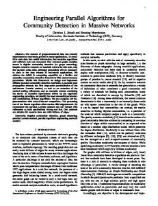
8.2 General Considerations Physical Model initialization time stepper post-processing
state vector time
106
Filter initialization analysis phase resampling phase
observation vector
Observations
state vector
observationvector measurement operator observations errors
4
>
Figure 8.1: Logical parts of the data assimilation problern.
The observations are independent both from the numerical model and from the filter. The filter routines require information On the observations (observation vector, measurement operator, observation error covariance matrix) in the a,nalysis phase. The model does not need information about the observations. To implement the measurement operator, however, information On the structure of the state vector is necessary. The physical meaning of the entries (velocities, temperatures, etc.) and their spatial location in the model mesh has to be known. Since the routines which initiahze the state ensembles also require this information, it can be shared between the ensemble initialization routines and the implementation of the measurement operator using Fortsm inodules. The framework can be logically partitioned into three parts as is sketched in figure 8.1. The transfer of information between the model and the filter as well as between the filter and the observations is performed via the API. The framework has to allow for the execution of multiple concurrent model evolutions, each of these can be pa,rallelized itself and thus be executed by multiple processes. Both, the parallelization of the model itself and the number of parallel model tasks have to be specified by the user. Like the model, the filter routines can be executed in parallel, too. We have discussed the parallelization of the filter routines in chapter 7. 0
The filter routines can either by executed by (some of) the processes used for the model evolutions or by a. set of processes which is disjoint from the set of model processes.
To combine a filter a.lgorithm with a numerical model in order to obta,in a data assimilation progra,m, we consider the 'typical' structure of a model which computes the time evolution of several physical fields. These can be, for example, the temperature and salinity fields in modeled ocean. The 'typical' structure is depicted in figure 8.2a. In the initialization phase of the program, the mesh for the computations is genera,ted. Also the physical fields are initialized. Subsequently, the evolution is performed. Here nsteps time steps of the model fields are computed. These take into account boundary conditions as well as external forcing fields, like e.g. wind fields over the ocean. At certain time-step intervals, some fields are typically written into disk files and diagnostic qmntities are computed. Having completed the evolution some post-processing operations can be performed. The structure of the data assimilation program with attached filter is shown in figure 8.2b. To initialize the filter framework, a routine Filter-Inzt is added to the initialization part of the program. Here the arrays required for the filter, like the ensemble matrix X, the mode matrix V or matrix U of the SEEK filter are allocated.
8.2 General Considerations
107
generate mesh
include BC
Do i=1,nsteps
Time stepper include BC
Figure 8.2: Flow diagiams a) Sketch of the typical structure of a model performing time evolution of some physical fields. b) Structure of the data assimilation configuration of the rnodel witli attached filter Added subroutine ca11s and control structures are shaded in gray.
8.2 General Considerations
108
Subsequently, the state estimate X; and the state ensemble or mode matrices are initialized. The major logical change when combining a filter algorithm with the model source code is that a sequence of independent evolutions has to be computed. This can be achieved by enclosing the time stepping loop by an unconditioned outer loop which is controlled by the filter algorithm. For each evolution the model obtains a model state from the filter algorithm together with the number of time steps to be performed. To enable the consistent application of time dependent forcing in the model the filter also provides the model time at t,he beginning of the evolution phase. The user has to assure that the evolutions are really indepenclent. Thus, any re-used fields must be newly initialized. In the framework, the model state. the model time ( t ) , and the number of time steps (nsteps) are provided by calling subroutine Get-Stute before the time stepping loop is entered. A value of nsteps = 0 uniquely determines that no stepping has to be performed. Thus, this setting is used as an exit-condition within the unconditioned outer loop. After the time stepping loop a subroutine Put-Stute is inserted into the model source code. In this routine the evolved model fields are stored back as a. column of the ensemble state matrix of the filter. If the ensemble forecast has not yet finished, no further operations are performed in the routine Put-Stute. When all model states of the current forecast phase are evolved, Put-Stute executes the analysis and resampling phases of the Chosen filter algorithm. For the parallelized version of the data assimilation program, further change to the model source code concerning the configuration of MPI communicators is required. For MPI-parallelized models there is typically a single model task which operates in the global MPI communicator MPI-COMM- WORLD. To allow for multiple model tasks which are executed concurrently, the global communicator has to be replaced by a communicator of disjoint process sets in which each of the model tasks operates. Thus, a communicator COMM-MODEL consisting of Nnx disjoint process sets has to be generated. In the model source code, the reference to MPI-COMM- WORLD has to be replaced by COMM-MODEL. Next to the communicator for the model a communicator COMM-FILTER has to be created defining the processes which execute the filter routines. To couple the filter processes with the model tasks another communicator COMM-COUPLE is required. Using this communicator, data is transfered between the filter and model parts of the data assimilation framework. The configuration of the MPI communicators is dependent On the choice whether the filter routines are executed by some of the model processes or on a set of processes which is disjoint from the set of model processes. In addition, the API for calling the subroutines Filter-Init, Get-Stute, and Put-Stute depends on this choice of the process configuration. For this reason, we discuss the two different configurations separately in the following sections. The implementation of the filter routines has been discussed in chapter 7. The names of user supplied subroutines are handled in the framework as subroutine arguments in the filter routines and have thus to be specified in the API. This allows the user to choose the subroutine names flexibly.
8.3 Framework for Joint Process Sets for Model and Filter
109
Subroutine Filter~Init(type-ass,subtype~ass,param-znt,dimJpint,param.real, dzm,-prea1,COMM-MODEL,COMM-FILTER, COA4M-COUPLE, modeltask,n-modeltasks, f zlterpeJnit,Enseinble,verbose,status) int type-ass {Type a filter algorithm, input} int subtype-ass {Sub-type of filter, input} int paranz-int(dim_pint) {Array of integer parameters, input} int dim_pint {Size of param-int, input} real param-real(dzm-preal) {Array of floating point pammeters, input} int dzm-preal {Size of param-real, input} int C O M M - M O D E L {Model communicator, input} int C O M M - F I L T E R {Filter communicator, input} int C O M M - C O U P L E {Coupling communicator, input} int modeltask {Model task the process belongs to, input} int n-modeltasks {Number of parallel model tasks, input} int f zlterpe {Whether the process belongs to the filter processes, input} external Init-Ensemble {Subroutine for ensemble initidization, input} int verbose {Whether to print screen information, input} int status {Output status flag of filter, output} I
Algorithm 8.1: Interface to the subroutine Filter-Init in the case of joint process sets for model and filter
8.3
Framework for Joint Process Sets for Model and Filter
First we consider the situation that the filter routines are executed by some of the processes which are used for the model evolutions. In this case, the internal variables of the filter algorithms are mainly stored using Fortran modules. With this, e.g., the ensemble matrix X or the Counter for the ensemble member t o be evolved can be shared between the different subroutines of the filter. The names of user supplied subroutines cannot be handled via modules. For this reason, the subroutine names have to be used as arguments in the call t o each routine using the particular subroutines.
8.3.1
The Application Program Interface
The three subroutines FdterJnit, Get-Stute. and Pnt-State provide a. defined interface to the filter algorithms. In addition, the user-supplied routines like the observation-related subroutines and the user analysis routine are called using a defined interface. We discuss here the interface t,o the three routines of the framework which are called from the model. The interfaces of the User supplied routines which are called by t,he filter are described in appendix B. The interfaces of these routines are equal for both process configurations. The implementation of the operations performed in these routines depend, however, on the choice whether a parallelization on basis of inode-decomposition or doma,in-decon~positionis used. The interface of the routine Filter-Inzt is shown as algorithm 8.1. This routine is called in the model source Code by all processes. For the initialization several variables are passed to the filter. With the integer argument type-ass the user chooses
8.3 F'ramework for Joint Process Sets for Model and Filter
110
Subroutine Get_State(nsteps,tzme,Next-Observation,Distribute-State, UserAnalysis,status) int n,steps {Number of time steps to be performed, output} real time {Model time at begin of evolution, output} external Next-Observation {Subroutine to get number of time steps and current time, input} external Distribute-Sta.te {Subroutine to distribute state in COMM-MODEL, input} external UserAnalysis {Subroutine for user analysis, input} int status {Output status flag of filter, output} I
Algorithm 8.2: Interface to the subroutine Get-Stute in the case of joint process sets for model and filter.
the filter algorithm to be used. For flexibility, su,btype-ass defines a sub-type OS the filter. This might be, e.g., a variant of SEEK in which the modes in matrix V are not evolved [33]. The array param-int is a vector of variable size dim-pznt. It holds integer parameters for the filters. In the current implementation of the filters dim-pint = 3 is set if the SEEK or SEIK filters are used. For EnKF, it is dim-pznt = 4. The first entry of param-int holds the dimension n of the state vector. The second entry specifies the ensemble size N for EnKF or the rank r of the approximated state covaria,nce matrix for SEEK and SEIK. The third entry specifies whether a parallelization with domain-decomposition or a decomposition over the modes of the ensemble matrix is used. For the EnKF the fourth entry is used to specify the rank of the inverse on the left ha.nd side of equation (2.47) if a pseudo inverse has to be computed. A value of Zero specifies that the solution OS equa,tion (2.47) is computed using the LAPACK routine DGESV. The array param-real of size dim-preal defines a vector of floating point parameters which are be required for some OS the filters. For SEIK and EnKF param-real has a size OS 1 and contains only the value of the forgetting factor p. For SEEK it is dzm-preal = 2. While the first entry of param-real specifies the forgetting factor p, the second entry sets the value of e Sor the gradient approximation of the forecast. The flexible sizes of param.int and param-real allow for future extensions OS the functionality. Next to these variables, the three communicators are handed over to the filter initialization routine. Further; the index modeltask of the model task of the process calling Filter-Inzt and the total number n-modeltasks of parallel model tasks is passed to the filter initialization routine. The argument f zlterpe specifies whether a process belongs to the filter processes. The name of the subroutine performing the ensemble generation is the next argument. The interface is completed by an argument which defines whether the filter routines will print out screen information and a final argument which serves as a status flag. It will have a non-zero value if a problem occurred during the initialization. The subroutine GetState is called in the model source code before the time stepping loop is entered. Get-State initializes the state fields of the model and provides the information On the current model time and the number of time steps to be computed, The interface to this routine is shown as algorithm 8.2. All parameters which are required by the filters have already been specified in the filter initialization.
I
8.3 Framework for Joint Process Sets for Model and Filter
111
Accordingly, the interface of Get-Stute contains only names of subroutines and output variables which are initialized for the model t.ime stepper. The variables nsteps and time, as well as the status flag status are outputs of the routine. In addition, the names of three subroutines are specified. The routines Next-Observation a,nd User-An,alyszs have already been described in section 3.3.1. The routine Dzstrzbute-State transfers a state vector to model fields arid distributes these within the model task defined by COMM-MODEL. In the variant with mode-decornposition, the fmrnework itself only initializes a state vector on a single process in each model task. The model-dependent opera,tions are then performed by the routine Dzstrzbute-State which is described in section 8.5. Having computed the evolution of a model state, this forecast is stored back in the ensemble or mode matrix of the filter algorithm. This is performed in the routine Put-Stute. If Put-Stute is called after the filter forecast phase has been completed, the analysis and remmpling phases are executed by this routine. In its interface, the names of several subroutines which are called by the filter analysis a,nd remmpling algorithms have to be specified. The observation-related routines Measurernent-Operator, Measurement, RznvA, RplusA, and Get-Dirn-Obs have already been discussed in section 3.3.2. The routine Measurernent-Ensemble is required in the EnKF. It provides the observation ensemble according to the observation error covariance makrix R. Collect-State performs the operation inverse t o that of the routine Dzstrzbute-Stute. That is, the ensemble fields in a model task are gathered in state vector. For mode-decomposed ensemble matrices, the state vector is gathered by a single process of this task. Next to the names of subroutines, the interface of Put-Stute contains again the status flag status as an output variable. The routine Put-Stute is generic for all three filter algorithms. Due to this, the interface requires the specification of all possible subroutine names, even if they are not required for all filters. For example, SEEK and SEIK only require the routine RinvA but not RplusA. The latter routine is required by the EnKF analysis while the former one is not used by this filter. To generate an executable program all
Subroutine Put.State(Collect_State,Get.Dim~Obs,Measurement.Operator, Measureinent~Measurement-Ensemble~User_Analysis,RinvA,RplusA,status) external Collect .Stake {Subroutine to collect state vector in COMM-MODEL, input} external Get-Dirn-Obs {Subroutine to provide dimension of observation vector, input} 1 external Measurernent-0vera.toi {Subroutine with implementation of measurement operator, input} external Measurement {Subroutine t.o initialize observation vector, input} external Measurement .Ensemble {Subroutine to initialize ensemble of observation vectors, input} external UserAna.lysis {Subroutine for User analysis, input} external RinvA {Subroutine for product of R 1 with some matrix, input} externd RplusA {Subroutine to add R to some ma,trix, input} int status {output status flag of filter, output}
1 1
I 1
Algorithm 8.3: Interface to the subroutine Put-State in the case of joint process sets for
model and filter.
8.3 F'ramework for Joint Process Sets for Model and Filter + logical
process number (= rank in MPI-COMM- W O R L D )
[O [O
2 [O
[O
[o
1 1]
11
3 1]
4 [0
[o 11
5 1]
6 [0 l]
71 1]
112
MPI-COMM-WORLD COMM-MODEL COMM-CO UPLE COMM-FILTER
Figure 8.3: Example coinmunicator configuration for the case that the filter is executed by some of the model processes and the filter routines use a parallelization of the modes.
three routines must be present (possibly as an empty routine, if it is not called by the chosen filter), since they are required for the linker step. To facilitate the implementation if only one filter type is used, we have implemented specific routines like Put-Stute-SEEK for the SEEK filter. The interface of the specific put-routines contains only the names of the subroutines relevant for the chosen filter. It would be possible to avoid the names of subroutines in the calling interfaces to Filter-In% Get-Stute, and Put-Stute. This would simplify the API considerable. On the other hand this would disable the possibility to use arbitrary names for the subroutines. We prefer this flexibility, since the User is not urged to use specific names for his subroutines.
8.3.2
Process Configurations for the Filtering Framework
Before we explain the functionality of the filter interface routines and the communication of data between the filter and the model part of the data assimilation program, we discuss the configuration of the MPI communicators. These define the process topology for the da,ta assimilation framework. In general, the data assimilation framework requires that the User initializes the communicators and provides the na.mes of these communicators to the routine Filter-Inzt. To facilitate the initialization of the communicators, the framework includes templates for these operations. These templates can be used in most situations without changes, but can be adapted when necessa,ry. The communicator configurations use simple 1-dimensional process topologies. Dependent On the model, it might be useful to a.pply other topologies inside the process sets of COMM-MODEL, e.g., to obtain optimal performance for 2-dimensional doinain decompositions.
A possible process configuration for mode-decomposition is shown in figure 8.3. In this figure each row corresponds to the communicator which is given on the right hand side. The processes are ordered from left to right according to their logical process number which is given by the rank of the processes in the communicator MPI-COMM- WORLD. Thus, the entries in a single column refer to the Same process. The number entries denote the rank of the process in the communicator. If no rank is given for a process in the context of some communicator, this process does not &tend in communications within this communicator. The brackets enclose processes which build together a process set on the communicator. In the example the program is executed by a. total of 8 processes. These are distributed into four parallel model tasks each executed by two processes in the context of COMALMODEL. The filter routines are executed by two processes. These are the
8.3 Framework for Joint Process Sets for Model and Filter
-
[O [O 101 [0
113
logical process nuinber (= rank in MPI-COMM- W O R L D )
1 l]
2 [O
[o] l
3 1]
4 [0
[Ol 2
5
l]
6 [O [01 31
71 l]
MPI.COMM.WORLD COhlM-MODEL COMM-CO UPLE COMM-FILTER
Figure 8.4: Example communicator configuration analogous to that in figure 8.3. Here the filter is executed by all processes which have rank 0 in COMM-MODEL.
processes of rank 0 and 4 in the context of MPI-COMM- WORLD. In the context of COMM-MODEL the filter processes have rank 0. Each filter process is coupled to two model tasks. Thus, there are two disjoint process sets in COMM-COUPLE each consisting of two processes. With this configuration, the filter initialization will divide the ensemble or the mode matrix into two matrices which a,re stored On the two filter processes. Each matrix holds a sub-ensemble of model states. For the utilization of all four model tasks, each filter process will a,gain distribute its sub-ensemble to the two model tasks which are coupled to it by COMM-COUPLE. A simpler configuration which will be sufficient for most applications is shown in figure 8.4. Again there are four parallel model tasks ea,ch containing two processes. The filter is executed in this configuration by each process which has rank 0 in the context. of COMM-MODEL. With this configuration, the cominunication scheme is simplified since no communication via C O M M C O U P L E is required. Each process set in COMM-COUPLE contains only a single process and the filter processes can directly provide data to the model tasks. Using this configuration, the state or mode ensemble is distributed into sub-ensen~blesin the routine Filter-Init. In contrast to the configuration in figure 8.3, no further distribution of the ensemble is necessary. If a domain-decomposition is used for the parallelization of the model and the filter parts of the program, the configuration of the processes is distinct from the case of mode-decomposition. considered is the situation that the filter uses the sa,me domain-decomposition of the states as the model. Figure 8.5 shows a possible process configuration. Here the program is executed by six processes in total. These are distributed into two model tasks each consisting of three processes. The filter routines are executed by all processes of one of the model tasks. Hence, the substate from this model task can be directly transfered between the local ensemble matrix and the model fields. The second model task is connected to the filter via COMM-COUPLE. With domain-decomposition, the initialization of the sub-states is performed in the initialization phase of the filter. The filter operates on the whole ensemble of local sub-states. To use multiple model tasks the ensemble is distributed into sub-ensembles. These are sent to the model tasks via COMM-COUPLE. A simplified configuration is possible which uses only a single domain-decomposed model task. This would lead to a trivial coupling communicator which consists of process sets containing a single process each. Thus. no communication in COMM-.COUPLE would be necessary and the overall MPI communication would be minimized. This configuration would, however, require a rnodel with very efficient parallelization. On the other hand. overall scalability would be limited, since only a single model evolution is computed at a time.
8.3 Framework for Joint Process Sets for Model and Filter
114
logical process number (= rank in MPI-COMM-WORLD)
[O
11 10
[O
1
1 [0 21
11
}
COMM-COUPLE
COMM-FILTER
Figure 8.5: Example communicator configuration for the case of domain-decomposed states. The filter is executed by some of the model processes.
8.3.3
The F'unctionality of the Framework Routines
To gain further insight in the functionality of the data assimilation framework, we discuss here the operations which are performed in its main routines. The filter algorithms are hidden behind the three subroutines Fzlter¥JnztGet-Stute, and Put_State. Due to this, the filter main routine, which was discussed in section 3.3.1, is split into two parts. These parts reside in Get-Stute and Put-Stute. Some additional operations are contained in these routines which are required for the parallel execution of the data assimilation framework. The interface to the routine Filter-Inzt has been shown in algorithm 8.1. Algorithm 8.4 sketches the operations which are performed in this rout,ine when the SEIK filter is used with a inode-decomposed ensemble matrix. The routine is called by all processes. Here several para,meters are initialized, like the chosen filter algorithm or the ensemble size. These parameters are sh&redbetween the filter routines using Fortran modules. All subsequent operations in Filter-Inzt are only performed by the filter processes. First, the sizes of sub-ensembles are computed. Subsequently, the arrays required for the filter a.re allocated. These are the state vector X and the local ensemble matrices Xp. In addition, the full ensemble matrix X is allocated on the filter process with rank 0. After the allocation of the fields, the user-supplied subroutine Inzt-Ensemble is called. For the SEIK filter, this routine initializes the ensemble matrix. If a parallelization with mode-decomposition is used, Inzt-Ensemble is only called by the process with rank 0. Here the full ensemble matrix is initialized. Subsequently, it is necessary to distribute sub-ensembles to all filter processes. This is performed by MPI communication operations. In the case of domain-decomposed stakes, the routine Inzt-Ensemble is called by all filter processes. The routine has to provide the full state ensemble for the local domain of each process. Since the state ensembles are readily initialized by all filter processes no further distribution of the ensembles is performed in FilterJnzt. A similar technique could be used for a mode-decomposed ensemble matrix. That is, Inzt-Ensemble is called by each filter process with the local sub-ensemble as argument. Then Inzt-Ensemble initializes only this local sub-ensemble. Since the sub-ensembles are readily initialized on the filter processes, no distribution of subensembles would be required in FzlterJnzt. Using this variant would avoid the storage of the full ensemble matrix on a single process. On the other hand the user would be obliged to implement Inzt-Ensemble such that all sub-ensembles are initialized correctly. From this point of view, the first variant, which initializes the
8.3 Framework for Joint Process Sets for Model and Filter
115
int rnype-f ilter {Rank of process in COMM-FILTER} int npes- f dter {Number of processes in COMM-FILTER} 1: initialize parameters 2: if f ilterpe == 1 then initklize local ensemble sizes Np 3: 4: allocate fields: X p ( n ,ATp),x(n) 5: if ,mype-fzlter == 0 then 6: allocate ensemble matrix X(n, N )
call Init-Ensemble(X) {Initialize full ensemble matrix} for i = 1,npes- f ilter do send sub-ensemble X(& : jp+rp- 1) to filter process i {With MPI-Send} 9: 0: end for 1: deallocate field X 2: eise if mype-filter > 0 then receive sub-ensemble Xp {With MPI operation MPLRecv} 3: 4: end if 5 : end if J l Algorithm 8.4: Sketch of the operations which are executed in the routine FilterJnit for the case of mode-decomposition. The interface to this routine is shown as algorithm 8.1 7: 8:
full ensemble matrix on a single process, is simpler to use. If memory limitations render the allocation of the full ensemble matrix on a. single process impossible, the initialization should directly operate On the sub-ensembles. To allow for this flexibility, Filter-Init contains both variants. The subroutine Get-Stute is called prior to each model state evolution. Its structure is sketched in algorithm 8.5 for the SEIK and EnKF filters. If the routine is called for the very first time, it calls the user analysis routine User-Analysis. This permits to analyze the initial ensemble consistently with the calls to User-Analysis which are performed during the assimilation. Also the ensemble counter member is set to one at the very first call to Get-Stute. For the remainder of the routine, this signals that a new forecast phase has to be performed. If Get-Stute is called in the beginning of a forecast phase (i.e., with member = 1). the routine Next-Observation is called by the process of rank 0 in COMM-FILTER. Next~Obseruationinitializes the number of time steps nsteps for the next forecast phase and the current model time time. Subsequently, the value of nsteps is distributed to all processes. If nsteps > 0, also the va,riable time is distributed to all processes by a broadcast operation. If the number of filter processes is smaller than the number of model tasks, as was the case in figure 8.3, the sub-ensemble of each filter process is further distributed such that each model task holds several ensemble members. This concludes the initialization of a forecast phase. When Get-State is called during a. forecast phase, it calls the user-supplied routine Distrzbute.State. Here the model fields are initialized from the state vector which is provided to Distribute-State as a subroutine argument. Since the state vector is
8.3 F'ramework for Joint Process Sets for Model and Filter
116
Subroutine Get-Stak(. . .) int firsttime {Flag whether routine is called the very first time} int, member {ensemble counter; shared using Fortran module} 1: if f i r s t t i m e == 1 then 2: call User-Analysis(. . .) 3: firsttime ^- 0 4: member +- 1 5: end if G: if member == 1 then if mype-fzlter == 0 then 7: call Next-Observation(step,nsteps,tzme){User supplied routine} 8: 9: end if broadcast nsteps to all processes {With operation MPI-Bcast} 10: 11: ifnsteps>Othen broadcast time to all processes {With operation MPI-Bcast} 12: dist,ribute sub-ensembles {With operations MPI-Send and MPLRecv} 13: 14: end if 15: end if 16: if nsteps > 0 then
call Distribute_State(n,Xp(:,member)) {User supplied routine} end if Algorithm 8.5: Sketch of the operations which are executed in the routine Get-Stute. The interface to this routine is shown as algorithm 8.2 17: 18:
only initialized on a single process of a model task, it might also be necessary to distribute the state information to the other processes of the model task. Dzstribute-Stute is not called directly by the model routines. Accordingly, the model fields or information 011 the model grid cannot be supplied as subroutine arguments. Thus. Distribute-State requires that the model fields are available via Fortran modules or 'common' blocks. We will discuss this issue in section 8.5. The routine Put-Stute is called after a model state has been evolved by the model time stepper. Algorithm 8.6 sketches the operations which are performed in this routine for the SEIK filter. During the forecast, the user-supplied routine CoLLect-State is called with the current ensemble stat,e vector as a,rgument. Also the ensemble counter member is increinented. Collect-State initializes the forecasted state vector from the evolved model fields. This is t h e inverse operation to that perforn~edby Distrzbute-Stute. We will discuss CoLLect_State in section 8.5. If the forecast of all ensemble members is not yet finished, the pr0gra.m exits Put-State and loops back to Get-Stute in order to evolve the next ensemble member. If the ensemble forecast is completed, the filter processes proceed in routine Put-Stute to perform the analysis and resampling phases of the filter algorithm. If there a.re less filter processes than model tasks. all ensemble members are gathered by the filter processes. Consecutively, the filter update phases are performed by calling SEIKAnalysis and SEIK-ResampLe and the User supplied analysis routine
8.4 Framework for Model and Filter on Disjoint Process Sets
117
Subroutine Put_State(.. .) int m m b e r {ensemble counter; sharecl using Fortran module} int A$ {local ensemble size; sharecl using Fortran module} I: call Collect-State(n,,Xp(:.member)) 2: nzenzber ^- member 1 3: if mem,ber = Np 1 then gather sub-ensen~bles {Wit,h operat,ions MPI-Send a.nd MPI-Recv} 4: if f ilterpe == 1 then 5: call User-Analysis(. . .) {User supplied routine} 6: call SEIK-Analysis(. . .) {Perform filter analysis} 7: call SEIK-Resample(. . .) {Perform resampling} 8: call User-Analysis(. . .) {User supplied routine} 9:
+
+
10: end if 11: member ^- 1 12: end if J Algorithm 8.6: Sketch of the operations which are executed in the routine Put-Stute. The interface to this routine is shown as algorithm 8.3 User-Analysis. After the update, the ensemble counter member is reset to olle and the filter proccsses exit Put-Stute. Only the filt,er processes perform the update. T h e remaining processes reset the ensemble counter and proceed directly to the routine Get-Stute. Here. they wait to receive the variable nsteps which is send from the filter process wit,h rank 0 in COMM-FILTER t o all processes by a broadcast operation (line 10 of algorithm 8.5).
8.4 Framework for Model and Filter on Disjoint Process Sets The variant of executing the model and the filter parts of the data assimilation program on disjoint process sets permits a very clear separation between these to parts of the program. All processes will call the filter i n i t i a l i ~ ~ t i routine. on Then, the filter processes proceed directly t o the filter main routine. The model processes will exit the initklization routine and proceed t o the model time stepper loop. During the d&taassimilation phase, the model and filter pats of the program are connected only by MPI communication.
8.4.1
The Application Program Interface
The application program interface in the case of disjoint process sets for model and filter consists aga.in of the three routines Filter-Init, Get-Stute, and Put-State. In addition, the observation-related subroutines and the routines Distribute-Stute and Collect-Stute are required. These routines can be identical to those routines which are used in the framework discussed in section 8.3.1. Finally, the user analysis
8.4 Framework for Model and Filter on Disjoint Process Sets
118
Subroutine FilterJmt(type~ass,subtype~ass,paramJint,dim-pint, param-real, dzm.preal,COIvIA/I.MODEL, COMM-FILTER, COMALCOUPLE, f dterpe,Init_Ensemble,Get_Dim-Obs,Next.Observation, Measurement_Operator,Measurement,Measurement _Ensemble,User_Analysis, RinvA,RplusA,verbose,status) int type-ass {Type a filter algorithm, input} int subtype-ass {Sub-type of filter, input} int param.int(di~n-pint) {Array of integer parameters, input} int dimJpint {Size of param-int, input} real paramJreal(dzmJpreal) {Array of floating point parameters, input} int dzm-preal {Size of param-real, input} int COMAJ-MODEL {Model communicator, input} int C O M A L F I L T E R {Filter communicator, input} int COMM-COUPLE {Coupling communicator, input} int modeltask {Model task the process belongs to, input} int n-modeltasks {Number of parallel model tasks, input} int fzlterpe {Whether the process is a. filter process, input} external Init-Ensemble {Subroutine for ensemble initialization, input} external Get-Dim-Obs {Subroutine to provide dimension of observation vector, input} external Next-Observation {Subroutine to get number of time steps and current time, input} external Measurement _Operator {Subroutine with implementation of measurement operator, input} external Measurement {Subroutine to initialize observation vector, input} external Measurement -Ensemble {Subroutine to initialize ensemble of observation vectors, input} external UserAnalysis {Subroutine for user a.nalysis, input} external RinvA {Subroutine for product of R 1 with some matrix, input} external RplusA {Subroutine to add R to some matrix, input} int verbose {Whether to print screen information, input} int status {Output status flag of filter, output} 4lgorithm 8.7: Interface to the subroutine Filter-Init in the case of disjoint process sets or model and filter.
8.4 Framework for M o d e l a n d Filter o n Disjoint Process S e t s
119
routine User-Analysis is required. The interface for this routine is identical to t h a t of the joint-process case. The interface of Filter-Init is shown as algorithm 8.7. It is called by all processes, to allow also for the initialization of parameters for the routines Get-Stute and Put-State which will only be executed by the model processes. The required parameters in the interface of Filter-Inzt are the same as in the case of joint process sets for model and filter. These parameters have been documented in section 8.3.1. Also the name of the subroutine performing the ensemble initialimtion has t o be provided. In the call to FzlterJnzt the API for disjoint process sets requires, in addition, the specification of the observation-related subroutines and the User analysis routine. This is necesmry since the filter processes directly call the main filter routine in Filter-In& FzlterJnzt is generic for all three filter algorithms. As for the routine routine Put-Stute in the case of joint processes in section 8.3.1,1'1 subroutine names have to be specified in the interface, even if they are not required for all filters algorithms. To facilitate the implementation, the framework also provides specific initialization routines for the filters. These routines require only the specification of the subroutines which are used for the particular filter. Algorithms 8.8 and 8.9 show respectively the routines Get-Stute and Put-Stute. As these routines a,re called from the model routine, they are only executed by the model processes. The routines receive and send the state vectors. Furthermore, Get-Stute receives the time stepping information. In addition, both routines control the transition between the state vector and the model fields. Direct outputs of Get-Stute are again the number of time steps (nsteps) and the model time at begin of the evolution (time). Next to these variables and the status flag status, only the subroutine Dzstribute~Stutehas to be specified. The functionality of Dzstribute-Stute is the same as in the case of joint processes for model and filter. The interface of Put-Stute is c ~ n s i d e r ~ bsimpler ly here than in the configuration with joint processes. Only the subroutine Collect-Stute has to be specified since the update routines of the filter are not directly called by Put~Stute.The status flag is given as the second argument of the interface.
8.4.2 Process Configurations for the Filtering F'ramework A possible process configuration for mode-decomposed ensemble matrices is shown in figure 8.6. The program is executed by six processes. There are two model tasks which are executed by two processes each. The remaining two processes are used to execute the filter. Each filter process is coupled to one model task by the communicator COMM-CO UPLE. Here, the communication in COMM-CO UPLE is always necessary, since it couples the disjoint process sets of filter and model. During the forecast phase each filter process sends the states of its sub-ensemble to the model task connected to it and receives forecasted state vectors. The model evaluations are performed only by the model processes while the filter processes wait for data. The filter analysis and resampling are computed only by the two filter processes. Meanwhile, the model processes idle. Figure 8.7 shows a possible configuration for domain-decomposed states. As before, six processes are used in total. Two processes are again used for the filter. The
8.4 F'ramework for Model and Filter on Disjoint Process Sets
120
Subroutine GetJState(nsteps,time,Distribute-State,status) int nsteps {Number of time steps to be performed, output} real time {Physical time at begin of evolution, output} external Distribute-State {Subroutine to distribute state in COMM-MODEL, input} int status {Output status flag of filter; output} int n {Model state dimension} real x(n) {State vector} int mype-model {Process rank in COMM-MODEL} if mype-model == 0 then receive nsteps in COMM-COUPLE {With opera,tion MPI-Recv} end if broadcast nsteps in COMM-MODEL {With operation MPI-Bcast} if nsteps > 0 then if m,ype-mode == 0 then receive time in COMM-COUPLE {With operation MPLRecv} receive X in COMM-COUPLE {With operation MPIRecv} end if broadcast time in COMM-MODEL {With operation MPI-Bcast} call Distribute-State(n,x) end if ets for model and filter.
Subroutine Put-State(Col1ect-State,status) external Collect-State {Subroutine to collect state vector in COMM-MODEL, input} int status {output status fla,g of filter, output} int n {Model state dimension} real x(n) {State vector} int mype-model {Process rank in COMM-MODEL} 1:
call CoIlect_State(n,x) if mype-model == 0 then 3: send X in COMM-COUPLE {With operation MPI-Send} 4: end if Algorithm 8.9: Pseudo code of the subroutine Put-State in the case of disjoint process sets for model and filter. 2:
8.4 F'ramework for M o d e l a n d F i l t e r o n Disjoint P r o c e s s S e t s
I
+ logical
[O
1
121
I
process number (= ra,nk in MPI-COMM- WORLD)
2
3
[O
1]
4 [O
51 1]
MPI-COMM-WORLD COMM-MODEL
J
11 COMM-FILTER Figure 8.6: Example comtnunicator configuration for the case that model and filter are executed by disjoint process sets and the filter routines use a paralleli~~tion over the modes of the ensemble ma.trix. 10
logical process number (= rank in MPLCOMM. WORLD) [0
[o
1
11
2
3
[0
1]
4 [0
5) l]
MPLCOMM-WORLD COMM-MODEL
COMM-FILTER
Figure 8.7: Example communicator configuration for the case of domain-decomposed states arid execution of model and filter parts by disjoint process sets. The example is analogous to that in figure 8.6. In contrast to the mode-decomposed case, each filter
process is coupled to respectively one process of both model tasks. forecasts a,re evaluated On two model tasks, each consisting of two processes. The communicator COMM-COUPLE now couples each filter process with respectively one process of both model tasks. Thus, during the forecast phase, filter process sends local state vectors to both model tasks. When all processes of a model task have received a sub-state, they start with the model evaluations.
8.4.3 Execution Structure of the Framework The data assimilation for disjoint process sets for model and filter exhibits a clear separation between the model and filter parts. Both a,re executed concurrently on their respective processes. A flow diagram for the framework which exemplifies the SEIK filter is shown in figure 8.8. The thick green lines symbolize communication. On execution of the program, the MPI communica,toor are initialized by all processes in global operations. Since in this phase of the program all processes are available. the User has t o take care that the subsequent model initialization is performed only by the model processes. The allocation and initialization of model fields is not required by the filter processes. After the model initialization, the filter initialization routine Filter-Inzt is called by all processes. In this routine, the model processes store the information On the communicators COMM-MODEL and COMM-COUPLE while the filter processes store the information on COMM-COUPLE and COMM-FILTER. Subsequently, the model processes exit the filter initialization routine. The filter processes proceed in FilterJnzt by allocating the arrays which are required for the chosen filter. Then the state vector X a.nd the ensemble matrix X or the mode matrix V are initialized and sub-ensembles are distributed to all filter processes.
8.4 Framework for Model and Filter on Disjoint Process Sets
122
Finally the filter processes call the filter main routine whose components are shown on the right hand side of figure 8.8. Having left the routine Filter-Init, the model processes proceed to the forecast loop shown on the left hand side of figure 8.8. In Get-Stute (see algorithm 8.8), the processes wait to receive the value of nsteps which is sent by the filter. If nsteps = 0, no forecast has to be performed. Thus, no further operations are necessary in Get-Stute and the forecast loop is exited. If nsteps > 0, the processes also receive the variable time and the sta.te vector X to be evolved. Subsequently, the routine Distribute-Stute is called which initializes the model fields on the basis of t h e state vector X. Then the evolution of the state is performed by the model time stepper. After the evolution, the routine Put-Stute is called. This routine is shown a s algorithm 8.9. Here Collect-Stute is called to initialize the forecasted state vector from the model fields on the model process with rank 0. Subsequently, this process sends the state vector X to the filter. This completes the forecast loop and the processes return to the begin of the unconditioned loop. The structure of the filter main routine on the right hand side of figure 8.8 is essentially the Same as that of the serial algorithm which we have discussed as algorithm 3.1. An addition to this algorithm is the subroutine Finulize-Model. 1t is required in the parallel program to send nsteps with a value of Zero to the model tasks. As discussed above, this signalizes to the model tasks to exit the forecast loop. The subroutine Forecust controls the loop over all ensemble members to be n disjoint proevolved. It is shown as algorithm 8.10. In the ~ o n f i g u r ~ t i owith cesses for filter and model, an algorithm is used which sends a only single ensemble state vector to the available model tasks. The filter part of the algorithm uses non-blocking MPI operations. These only post the communication operation arid immediately return from the function even if the communication operation is not yet completed. In contrast to this, the routines Get-Stute and Put-Stute apply blocking MPI operations to ensure that the data has been received or send completely. Sending and receiving single state vectors permits a flexible handling of the forecast phase. If forecasted state vector is received back from some model task, a new ensemble state vector can be send immediately to this task if there are any ensemble states left. For sufficiently large ensembles, this ensures a good load balancing since faster model tasks can evolve more ensemble states than slower model tasks. This algorithm is more flexible than the configuration used for joint process sets for filter a,nd model. There the sizes of sub-ensembles are Set during the initialization phase of the framework. In addition, the memory requirements are smaller here. In the case of mode-decomposition, a single state vector is allocated on the model processes with rank 0 in COMM-MODEL. No filter-related memory allocations are required on the remaining model processes. For domain-decomposition a single sub-state is allocated on each model process. For the configuration using joint process sets for filter arid model, it is required to allocate sub-ensembles of state vectors.
8.4 Framework for Model and Filter on Disjoint Process Sets
123
I
Initialize Communicators I
generate mesh init of fields
1
i Get-State
nsteps, time, state
E nsteps=O'
'
User-Analysis
nsteps>O?
false
4true Forecast
4
state
User-Analysis
include BC include forcing
-1
User-Analysis
Figure 8.8: Flow diagram for the framework when filter and model are executed by disjoint process sets. Exemplified is the program flow for the SEIK filter. Shaded in gray are the routines of the filter framework. The thick black lines denote commu~~ication. The parts of the program which are horizontally centered are executed by all processes. After the initialization, the program splits into the model part displayed On the left liand side and the filter part on the right hand side. Both parts are connected by communication operations.
8.4 Framework for Model and Filter on Disjoint Process Sets
124
Subroutine Forecast(step,nsteps,time) int step {Current time step, input} int nsteps {Numbcr of time steps to be computed, output} real time {Current model time, output} int n {Model state dimension} int Np {Size of local state ensemble} real Xp(n, N p ) {Local state ensemble} int npes {Number of processes in COMM-COUPLE} int status(npes - 1) {Status a,rray; idle: 0, working: l} int send-ens {Counter for ensemble member to become evolved} int get-ens {Number of received state vectors} status(1 : npes - 1) + 0 {Set status to idle for all tasks} send-ens +- 1 {Send first ensemble member} get-ens + 0 {No state received yet}
loop for task = 1,npes - 1 do if status(task) == 1 then Test whether receiving from task has been completed {With operation MPI-Test} if receiving of task completed then get-ens + get-ens 1 {Increase counter of received states} status(task) + 0 {Set task to idle}
+
end if end if if statusttask) == 0 then send nsteps t o task {With operation MPLISend} send time to task {With operation MPI-ISend} send Xp(:, send-ens) to task {With operation MPUSend} post receiving of Xp(:, send-ens) from task {Operation MPLIRecv} send-ens + send-ens 1 {Increase index of member t o send} status(task) + 1 {Set task to working}
+
end if end for if get-ens
== Np then
Exit loop
end if end loop ~lgorithm8.10: Structure of the routine of the filter framework which controls the ensenlble forecast in the case of SEIK and EnKF. (For SEEK, the state estimate itself is also evolved. Hence, the forecast routine for SEEK contains an extension for evolving the state estimate.) The used MPI operations are non-blocking. Thus, the algorithm directly proceeds after posting a MPIJSend or MPURecv operation.
1
8.5 Transition between the State Vector and Model Fields state vector
125
rnodel fields
Figure 8.9: Transition between the abstract state vector (left hand side) and the model fields (right hand side). Shown is an example of three model fields of equal sizes. This example originates from the experiments with the shallow water model discussed in chapter 4. u and V are the two horizontal velocity components while h is the surface elevation.
8.5
Transition between the State Vector and Model Fields
The filter algorithms operate solely on the abstract state vectors. All operations which require information on the physical nature of an element of the state vector are performed in user-supplied routines. The arrangement of elements in the state vector is defined in the initialization routine Init-Ensemble. Here the user choses how to order the information On different physical quantities and from different physical locations. The observation-dependent routines have to consider this ordering to allow for a consistent implementation, e.g., of the measurement operator or the initialization of the observation vector. The arrangement of the elements in the state vector is also important in the routines Distribute-Stute and CoLLect-State. These routines are executed by all model processes. In contrast to this, the other usersupplied routines, are executed only by the filter processes. Figure 8.9 exemplifies the transition between the abstract state vector and model fields for the experiment using the shallow water equations which has been considered in chapter 4. The model consists of three fields, namely, the two velocity components U, V and the sea surface elevation h. Each of these fields is 2-dimensional. For the filter, the model fields are stored successively in the 1-dimensional state vector. The routine Distrzbute-Stute is shown as a,lgorithm 8.11. It is called from the routine Get-Stute. The purpose of Dzstrzbute-Stute is to initialize the model fields from the state vector such that the state information is sufficiently initialized for the model time stepper. If Distrzbute-Stute is called in the case of a. mode-decomposed ensemble matrix, a full state vector X of dimension n is initialized by a single process of the model task. lf the model task consists of a. single process, the model fields can be directly initialized, e.g., by copying the data into the model fields. If the model task consists of multiple processes, the required operations depend on the type of the parallelization.
8.5 Transition between the State Vector and Model Fields
126
Subroutine Distribute-State(n:x) int n {State dimension, input} int x(n) {State vector to be distributed, input}
1
. . . Initialize and distribute model fields . . . Algorithm 8.11: Interface of the subroutine Distribute-State ~vhichperforms the transition from the state vector of the filter and the model fields.
1
For example, the finite element model which will be used in the experiments in chapter 9 requires that, the model fields are fully initialized on all processes. Thus, the model fields are first init.ia1ized in Dzstrzbute-Stute on the process which holds the state vector. Subsequently, the model fields are distributed to the other processes in the model taslc by MPI operations. If Dzstribute-Stute is called in the case of domain-decomposed states, each model process holds that pa.rt xp of the state vector which corresponds to its local domain. Hence, Dzstrzbute-Stute will perform only t.he initialization of the model fields in the local domain. As long as the domain-decomposition of model and filter coincide, no communication operations a.re necessary. The routine Collect-Stute is shown as algorithm 8.12. It performs the inverse operations to those of Dzstrzbute-Stute. If doma,in-decomposition is used, the local state vector is initialized on each model process. For mode-decomposition, the state vector, which is allocated on one of the model processes, is initialized using the evolved model fields. If the state information is distributed over the model processes, it is necessary to @her them with communication operations on the process holding the state vector. With the finite element model used in chapter 9, the evolved model fields a.re fully initia,lized on all processes of the model task. Hence, no communica.tion operations a.re required.
Subroutine Collect-State(n,x) int n {State dimension, input} int x(n) {State vector to be distributed, input}
1I . . . Initialize state vector from model fields . . .
1
I
Algorithm 8.12: Interface to the subroutine CollectLState which i~~iti~lizes a state vector from the model fields. A particular issue of the routines Dzstrzbute-Stute and Collect-Stute is tha.t they are not directly called by the model routines. This structure of the interface permits to hide these filter-related operations from the model. It has, however, the drawback tha.t model-specific va,riables and arrays cannot be used as subroutine a,rguments. In pa.rticular, the arrays holding model fields and variables with specifications of the model grid cannot be provided as subroutine arguments. Hence, it is necessary to use Fortran modules or common blocks to provide the routines Distrzbute-Stute a.nd ColLect~Stutewith model fields and specifications of the model grid. For models fulfilling these implementation issues, the framework can be used with the clear separation between model and filter. If, however, a model does not support this type of storage, an alternative implementation of the routines Get-Stute and Put-Stute is necessary.
8.6 Summarv and Conclusions
127
Subroutine Get~State~Alt(n,steps~tzme~n,x,status) int nsteps {Number of time steps to be performed>output} real {Physical time at begin of e v o l u t i ~ noutput} ~ int n {Model sta.te dimension,input} real x(n) {State vector~output.} int status {Output staius flag of filter, output} I
I
Algorithm 8.13: Alternative interface of the subroutine Get-State in the case of disjoint process sets for ~nodeland filter. The initialization of model fields is not performed in the subroutine, but the state vector X is an argument of the interface. This permits to initialize tlle model fields directly in the model routines. Algorithm 8'13 shows the alternative va.ria.nt of Get-Stute for the configuration using disjoint process sets for model and filter. The algorithm is compa,rable with the original implementation shown as algorithm 8.8. The routine Dzstrzbute-Stute is not called in the alternative impleinentation. In addition, the interface is changed to include the state dimension n and an arsay x(n) for the state vector. This a.rsay has to be allocated in the model source code. In Get-Stute-Alt, the state vector X is initialized on a single process if mode-decomposition is used. Fos domaindecomposition, a sub-state for the local domain is initialized On all processes. Since the sta,te vectors 're known in the model context in this alternative implementation> it is possible to initialize the model fields without using Fortran modules OS common blocks.
8.6
Summary and Conclusions
A framework for parallel data assimilatioi~based On 1Calina.n filter methods was introduced. The framework is basecl on a. clear separation between the model: the filter, and the observational parts. This allows for a structure which requires only minimal changes in an existing model source code when a data assimilation System is implemented using the filter framework. With the frame~vork> an application program interface was introduced which defines the calling structure of the frame~vork routines which a,re called by the model. Also the interfaces to uses-supplied routines are defined. These are, e.g., routines which are related to the observa.tions or routines to transfer the skate vectors used in the filter algorithms to model fields and vice versa,. The interface pennits to switch easily between different filter algorithms. In addition: changes to the model a,nd filter source codes can be conducted independently. The framework was introduced for two different process configurations. The filter ca.n either execute by some of the model processes (which is denoted below as joint process sets) or the filter and model parts are executed by disjoint process sets. Both variants permit to handle domain-decomposed state vectors as well as a parallelization ~irhichdecomposes of the ensemble or mode n~atricesover the modes. To compa.re the two different process configura.tions of the fran~ewosk:advantages and drawbacks of the two configurations are summarized in table 8.1. A major drawback of the configuration using joint process sets is that at least a pa.rt of the ensemble OS model matrix has to be allocated on one process of each
8.6 Summary and Conclusions
128
Table 8.1: Advantages (+) m d drawbacks (-) of the fra.meworks for the two different process configurations.
one process set for filter a.nd model allocation of sub-ensemble On one process of each moclel task - allocation of filter fields on those model processes which are also filter processes + no additional processes required for the filter pa,rt -
+ + -
+
reduced amount of communication if the n ~ ~ m b of e r model tasks equals the number of filter processes
-
+
model grid information allocated also on filter processes load balancing of t,he forecast by- a priori specifica,tion of sub-ensemble sizes inflexible possibilities of process configurations to achieve good load balance
-
-
-
+ +
disjoint process sets allocation of a single st,ate vector on one process of each model task allocation of filter fields on processes separate from the model processes processcs additional to the model processes are necess'ry for the filter part high amount of communication, since each model state vector has to be comn~unica.tedbetween filter and model processes model grid information not allocated on filter processes flexible load balancing due to communication of single model state vectors flexible choice of process configurations; model and filter can even be executed On different computers
model task. This can considerably increase the memory requirements of these processes, which also hold fields needed by the model. In addition, fields which are required for the analysis and sesampling phases of the filters are allocated On those processes which are also filter processes. These memory requirements can be critical if the computer used for the data. assimilation computations poses strong memory limitations. The issue of memory requirements is minor for the case of disjoint process sets. Here only a single state vector is allocated on single process of each model task. The fields which are required for the filter operations a.re allocated On the filter processes which are separated from the model processes. An advantage of the configuration using joint process sets is that the execution of the filter does not require additional processes. All processes of the program are used for model evaluations. In contrast to this, additional processes for the filter part of the program: besides the processes performing the model evaluations, are required for the config~~ration using disjoint process sets, During the forecast phase, these processes only send control information for the forecast, and communicate state vectors. For la,rge-scale ocean models, the forecast of a state vector takes ~ignific~ntly longer than the communication between the filter a.nd model processes. Due to this, the filter processes will idle niost of the time. Besides the requirement of additional processes for the filter, the configuration nlore data tha.n the variant using joint with disjoint process sets comm~~nicates process sets. This is due to the fact that all ensemble state vectors, which have to be evolved, need to be send from the filter processes to the model processes and vice
8.6 Summary and Conclusions
129
versa. For a. parallelization using mode-decomposed matrices, the least amount of communica,tion is required in the case of joint process sets if the number of filter processes equals the number of model tasks. In this situation, a sub-ensemble is allocated On each filter process. The comm~~nication reduces to that amount which is necessary to distribute the state information to all processes in a model task. For domain-decomposed states, the amount of communications between filter and model can be reduced to Zero if the configura,tion of joint process sets and a single model task is used. A further potential advantage of the configuration using joint process sets lies in the fact that the information On the model grid is also allocated On the filter processes. This ca,n be beneficial: e.g., for the implementation of the measurement operator if it requires informa.tion On the spatial positions of observations and t h e elements of the state vector. In the case of disjoint process sets, this information has to be initialized separ'tely from the model. In addition to reduced memory requirements, the configuration using disjoint process sets is significa,ntly more flexible in the configuration of the MPI communicators. Since only single model states are communicated between filter a,nd model tasks, possible deviations in the speed of different model tasks are easily balanced by evolving nlore states with the faster model tasks than with the slower ones. This flexibility cannot be achieved with joint process sets. Due to the strong separation of filter and model, the configuration using disjoint process sets even permits t o execute the filter pa.rt of the program On a different computer than the model tasks. Also it is possible to execute model tasks On different computers or to compute forecasts concurrently using different models. Concluding, this comparison showed, that neither the configuration with joint n disjoint process sets for the filter and model process sets nor the c o n f i g ~ r ~ t i ousing parts of the program is clearly prefenble. The variant with joint process sets should be preferred if the computer memory perrnits to store sub-ensembles as well as the fields required for the filter analysis and resa.mp1ing algorithms On the Same processes as the model fields. Joint process sets permit to use all availa,bleprocesses for the model evaluations and reduces the amount of communicated data. If it is not possible to store the filter fields On the sa.me processes as the model fields, the variant using disjoint process sets for filter and model is preferred. This variant should also be chosen if the Llse of multiple computers is desired to solve the data assimilation problem.
Chapter 9 F'iltering Performance and Parallel Efficiency 9.1
Introduction
The parallel filtering framework developed in the preceding chapter 8 has been implemented with the Finite Element Ocean Model (FEOM) [12]. The implementation also includes the pa.ralle1ized filter algorithms developed in chapter 7. FEOM is parallelized using MPI. h!Iainly the solver step, required for the implicit time stepping schen~eof FEOM, is performed in parallel. The model state fields have to be fully alIocated a.nd initialized by all nlodel processes. The data assimilation system, which is obtained by combining FEOA11 and the filtering framework, is used to study the parallel efficiency of the framework and of the filter algorithms. In addition, the filtering performance of the three error subspace Kalman filters is ana.lyzed on the basis of twin experiments. These experiments extend the t,win experiments performed in cha.pter 4 to a 3-dimensional test-case. The data assimilation experiments are perfornied with an idealized configuration of FEOM using a recta.ngu1ar grid. Assimilated are synthetic observa,tions of the sea surface height. The major properties of the finite element model FEOM are described in section 9.2. Subsequently, in section 9.3, the configura.tion of the twin experiments is describecl in detail. The filtering performa.nce of tlle three error subspa.ce Kalman filters SEEK, EnKF and SEIK is examined in section 9.4. Here the abilities of the filter a.lgorithms accurately estimate the 3-dimensional model fields is studied. The parallel efficiency of the framework and the filter algorithms is finally assessed in section 9.5.
9.2
The Finite Element Ocean Model FEOM
The finite ele~nentocean model FEOM has been developed recently at the Alfred Wegener Institute [12]. It is a three-dimensional model designed to study the thermohaline circulation of the ocean on basin to global scales for periods from years to decades. The data assimilation framework introduced in chapter 8 permits to use this model as a 'black box' to perform the required model forecasts. In particular,
9.2 The Finite Element Ocean Model FEOM
131
the filter routines are independent from the discretization method - finite elements. finite differences, or others - used to compute the forecasts. A detailed description of FEOM has been given by Danilov et al. 1121. Here only the major properties of this model are summarized. FEOM is based on the primitive equations, see e.g. [72]. which describe the thermo-hydrodynamics of the ocean. Namely, the primitive equations govern the velocity field (C, W ) = (U,v, W ) , the Sea surface height C, and the baroclinic pressure anomaly P. Further, the sea w&er density po P, where po is the mean density, the temperature field T , and the salinity field S are described in the spherical coordinate system (X, 6 , z ) by the equations
+
Here, f is the Coriolis parameter and k is the vertical unit vector. Ai, Au are the lateral and vertical momentum diffusion coefficients. g is the gravitational acceleration. nf and are the lateral and vertical diffusion coefficients for the temperature. The corresponding coefficients for the salinity are and 68. The bottom of the ocean is at -Ho(\, 0). @(T, S,p) denotes the equation of state. It is used to compute the density p from the temperature, salinity, and pressure fields. The primitive equations are discretized on an unstructured grid with variable resolution. This 3-dimensional grid is built by tetrahedral elements. It is generated from a 2-dimensional triangular grid at the ocean surface which defines vertical prisms. Elementary prisms a,re obtained by subdividing the vertim1 prisms by level surfaces. The elementary prisms are split into t e t ~ ~ h e d r o n sThe . model fields are approximated using linear basis functions on these elements. A backward Euler method is used for the time stepping. The system of linear equations, which results from the finite element discretization, is solved by algorithms which are implemented in FEOM using the Family of Simplified Solver Interfaces (FoSSI) by Frickenhaus et al. [23]. FoSSI provides common interfaces to various solver libraries for sparse systems of linear equations like PETSc 1641 or the solver PILUT by Karypis arid Kumar [43]. Danilov et al. [I21 tested the model performance in a configuration for the North Atlantic. Due to the size of 86701 nodes of the 3-dimensional grid, it is not feasible to use this configuration for the data assimilation arid speedup experiments performed here. For this reason, the experiments employ an idealized configuration of FEOM. The configuration uses linear density stmtification and a linear equation of state @(T,S , p ) . Further, convection is neglected and the rigid-lid approximation is used. The model domain is given by a rectangular box geometry with a structured
9.3 Experimental Configurations
132
grid. It is shown in figure 9.1. The box is centered at 44.5O north and occupies an area of 9 by 9 degrees. It has depth of 4000m. The discretization comprises 11 vertical levels and a horizontal grid of 31 by 31 points. This amounts to 10571 nodes of the 3-dimensional grid and 961 surface nodes. The time evolution is performed with a time step of 3 hours. The salinity field is chosen to be constant over the model domain. The state vector for the filters consists of the zonal and meridional velocity components U, V, the temperature T, and the sea surface height C. Apart from the 2-dimensional sea surface height, all of these are 3-dimensional fields. Hence, the state dimension amounts to n = 32674.
9.3
Experimental Configurations
To extend the examination of filtering performance presented in chapter 4 and to study the parallel efficiency of the filter algorithms, identical twin experimcnts are performed with the idealized configuration of FEOM. Synthetic observations only of the sea surface height are assimilated. The physical process which is simulated in the assimilation experiments is the propagation of interacting baroclinic Rossby waves. The waves are initialized with two h o r i ~ o n t ~ l localized ly columnar temperature anomalies of the sa,me amplitude but opposite sign. This initialization is shown in figure 9.2. Propagating westward, the anomalies become deformed. They tilt toward each other via the induced velocity field. That is, a negative temperature anomaly produces a counterclockwise rotation in the upper levels arid a clockwise rotation in the lower levels. The rotation of a positive temperature anomaly is vice versa. These opposing rotations introduce non-Iinearity which is necessary to test the filtering performance of the error subspace Kaiman filters. The data assimilation experiments are conducted over a period of 40 days. The interval between subsequent analyses is set to 2.5 days. For the twin experiments the "true" state trajectory is generated by integrating the initialization displayed in figure 9.2 over a period of 45 days. To generate synthetic observa,tions of the sea surface height, Gaussian noise with constant variance of 0.01 m2 is added a t exh time step to the sea surface height field of the true state sequence. The arnplitude of the temperature anomalies, and thus of the sea surface height, decreases over time. This is caused by diffusion. Hence, the relative noise amplitude of the observations increases during the a ~ s i m i l ~ t i operiod. n Initially the standard deviation of the noise in the observations is at about 20 percent of the amplitude of the true surface height. After 45 days, the errors in the observations increased to about the Same level of the surface height itself. The generated observations a,re used with an offset of 5 days in model time. Assimilating only observation of the sea surface height, the dimension of the observation vector amounts to m = 961. Figure 9.3 compares the observed sea surface height field with the true one at the initial time of the experiments. The observation errors are clearly visible, but d s o the observed information is apparent. To initialize the filter in the twin experiments, the covariance matrix of 2268 state vectors is computed. These vectors are generated by 28 model forecasts using different initial loc&tions of the temperature anomalies. Further, an additional variante of the sea surface height fields of 0.lm is assumed. The obtained covariance matrix. which describes the temporal variations and correlations of the model fields, is used as the initial error estimate in the filter experiments. The initial state
9.3 Experimental Configurations
experiments. I t consists Figure 9.1: FEOM model grid used for the data assimil~~tion of 10571 nodes. Vertical levels are a t the surface and in the following depths: 7.5, 20, 50, 100, 500, 1000, 2000, 3000, 3800, and 4000 meters. The coloring shows the linear temperature stratification.
40
0
*e9.2: Cut into the model grid showing the temperati
nalies.
9.3 Experimental Configurations True sea suriace height
t,
134 Observed sea suriace heiqht i,
Iongitude
Figure 9.3: Comparison of the true (left) and the observed (right) sea surface height field C at the initial analysis update.
estimate for the twin experiments is chosen as the mean state of the 28 model runs. The generation of the state ensembles for SEIK 'nd EnKF and the initialization of the mode matrix for SEEK is performed as described for the experiments with the shallow-water-equation model in chapter 4. To exa,mine the abilities of the filter algorithms to cstimate the true state from the chosen initial state, an evolution of the initial state estimate is performed without assimilating observations. This state sequence is denoted the "free" state trajectory. To simulate model errors in the application of the EnKF and SEIK filters, a wind forcing field of two gyres is applied whose shape and amplitude are controlled by two parameters. To obta.in a stochastic forcing, these parameters are initialized by random numbers. Each ensemble member was forced by a different wind field which was constant over the forecast period. To retain comparability, the SEEK filter was used without a forgetting factor, since this could be applied to all three filters, or explicit treatment of a model error covariance matrix. Thus, the twin experiments using SEEK are performed without consideration of model errors. Most of the computation time is spent in evolving the model states. Since the computation time is usua,lly a limiting factor in data assimilation problems, results for assimilation experiments are compared in which all filters perform the same number of model evaluations. This configuration provides comparable execution times for assessing the pa,rallel efficiency of the three filter algorithms. To obtain configurations with equal numbers of model evaluations, the rank r used in SEEK and SEIK is set to r = N - 1 where N is the ensemble size of the EnKF. The experiments have been performed on a Sun Pire 6800 Server with 24 processors, each having a frequency of 1050 MHz.The experiments in section 9.4 used the solver PILUT while the experiments in section 9.5 used PETSc. This different choice was motivated by the fact that the use of PILUT resulted in inferior speedup values than PETSc. In contrast to this, the assimilation experiments with
9.4 Filterine Performance
135
the PILUT solver provided a better filtering performance than those using PETSc. Since this work is not aimed at the optimization of the model, the solver was chosen depending on the best results either in terms of filtering performance or in terms of speedup.
9.4
Filtering Performance
Before the parallel efficiency of the filter algorithms is studied in section 9.5, the filtering perform'nce of the SEEK, SEIK, and EnKF algorithms is assessed for their application to the configuration of FEOM described in the preceding sections. These experiments extend the 2-dimensional experiments of cha.pter 4 to a 3-dimensional test-case.
9.4.1
Reduction of Estimation Errors
For an ensemble size of N = 60, figure 9.4 shows the rms deviation E1 of the assimilated state from the true state normalized by the rms deviation of the free state from the true state. The deviation is computed over all grid nodes with equal weights for all nodes. Thus, no volume-normalization is performed which would consider the different distances between neighboring levels of the model. The relative estimation error is disphyed separately for the four state fields. For 7V = 60, the EnKF and SEIK filters yield comparable results. For smaller ensembles, the difference of Eifor the two filters is larger, with the EnKF performing worse than the SEIK filter (not shown). This can be expected because of the inferior sa,mpling quality of the Monte Ca,rlo sampling applied to initialize the EnKF algorithm. Since the difference of the mmpling quality decreases for larger ensembles, the results of EnKF and SEIK become &lmost identical for larger ensembles. The SEEK filter shows a behavior distinct from the two other algorithms. This behavior is caused by the forecast scheme of the SEEK filter which applies a gradient approximation of the linearized forecast of the covariance modes. For all model fields the relative estimation errors tend to increase toward the end of the assimilation period. This is due to the growing relative error level in the observations which is discussed in section 9.3. The largest error reduction is obtained for the sea surface height (,. As observations of the sea surface height are assimilated, this field is expected to show the smallest normalized estimation error of the four model fields. To get an idea of what represents the achieved reduction of the relative estimation error to about 0.27 for the sea surface height, the left hand side of figure 9.6 shows in the uppermost panel the true sea surface height a.t the end of the assimilation period. In the middle panel, is shown as estimated by the EnKF filter with N = 60. The sea surface height which is obtained from the free evolution, i.e. when the initial state estimate is evolved without assimilation, is displayed in the lowermost panel. The sea surface height estimated by the EnKF algorithm reproduces accurately the shape of the true C,. The locations of the minimum and the maximum are well estima,ted. The amplitudes are underestimated by about 10%. In contrast to this, the sea surface height without assimilation deviates strongly from both the true and SEIK-estimated (,.
9.4 Filterine Performance
136
The velocity components u and V are updated via. the estimated cross correlations between the sea surface height and the velocity components. Despite this, the relative estimation errors of the meridional velocity component U are of comparable size to those of the sea surface height in the case of EnKF and SEIK. This relation shows, that the cross covariances are estimated quite well by the nonlinear ensemble forecast. In contrast to this, the linearized forecast performed in SEEK yields much worse estimates of the cross covariances. This can be deduced from the much larger estimation errors for U obtained with SEEK. The estimate of the zonal velocity component V is less precise than the estimate of u for all three filters. After the first analysis phase, the estimation error of both velocity components is of comparable size. While the estimation error for U decreases during the Course of the assimilation experiment, the estimation error for V remains at a level of about 0.4 when using the EnKF or the SEIK filter. Thus, the
-
-
0.2 L 0
0.2
'
0
10
EnKF SEEK SEIK
20 time [day]
30
20 time [day]
30
40
time [day]
l
10
40
Figure 9.4: Time dependence of the relative estimate errors EI for experiments with N = 60. Shown is Ei separately for the sea surface height (top left), the temperature field T (top right), and the two components U, V (respectively on the left and right hand
sides of t,he bottom row) of the velocity fields.
9.4 Filterine Performance
137
cross covariances are not estimated sufficiently precise to further decrease the error level for this velocity component. During some analysis updates, e.g. at day 25. the estimation error increases. In this case the estimated cross covariances have t h e wrong sign. The relative estimation error of the temperature field T shows a behavior distinct from the other model fields. The error reduction at the first analysis update is smaller for T tha,n for t,he other fields. For the EnKF arid SEIK filters, the relative estimation error of the temperature field increases immediately after the first analysis update. Further, the estimation error remains almost unchanged during the analysis update. Thus, no useful estimates of the cross correlations are available after the first analysis update. The estima,tes of va.riances and correlations within some model field are typically much more precise tha,n estimated cross correlations. Thus. even a. limited number of temperature measurements would enhance the estimation quality of the temperature field for all three filters.
9.4.2
Estimation of 3-dimensional Fields
To examine the ability of the filter algorithms to estimate the 3-dimensional model fields by assimilating only surface measurements profiles of the relative estimation errors a t the end of the assimilation period are shown in figure 9.5. The values displayed in the diagrams are the normalized rms estimation errors computed over single levels of the model.
-40000
02 04 06 08 normalized E,
1
I
Figure 9.5: Profiles of the rms estimation errors of single layers normalized by the corresponding rrns deviation of the free state from the true state for N = 60. Shown are the two components U, V of the velocity fields and the values for the temperature field T at the end of the assimilation period.
9.4 Filterine Performance
138
The profiles for the two velocity components U and V, displayed On the left and middle panels, show a small relative estimation error from the surface to -1000m depth. Below -3000m the estimation error is a also small, but it increases toward the bottom. At the depth of -2000m the estimation error shows a maximum. For the experiments with SEIK and EnKF, this maximum is even larger than one. The estimation errors obta,ined with SEEK are of similar size to those achieved by the EnKF and SEIK filters. They are, however, larger at all depths, except at -2000m. For all three filters, the relative estimation errors are smaller for the meridional velocity component u than for the zonal velocity V. The peak in the relative estimation error at the depth of -2000m is due t o the normalization by the estimation error of the evolution without assimilation. As has been described in section 9.3, the temperature anomalies generate a.counterclockwise rotation in the upper levels and a clockwise rotation in the lower levels. The turning point of these rotations is approximately at the depth of -2000m. Due t o this, the velocities are minimal at this depth in the true state, the free state and the assimilated states. This causes minimal rms deviations of the velocities of t h e free evolution from the velocities of the true evolution. Without normalization, the estimation errors of the assimilated velocities are of comparable size to those of the non-assimilated velocities at -2000m depth. Due to the normalization, the estimation errors appear larger than their absolute value. The increase of the relative estimation error below -3000m is not due to the normalization, as the absolute estimation errors also increase below -2000m depth. Thus, the quality of covariances between the sea surface height and the velocity fields is worse in the deep ocean than for the upper levels. Overall, all three filters show good abilities to reduce the estimation error of the velocity field also in the lower levels of the model. The level -2000m appears to be a rather pathological ~ i t u ~ t i owhich n the algorithms cannot handle well. The profile of the relative estimation errors of the temperature field, shown on the right hand side of figure 9.5, exhibits a different dependence on depth than the estimation errors of the velocity field. In the uppermost levels the estimation error of the temperature field is not reduced by the SEIK and EnKF algorithms. In contrast to this, the relative estimation error is decreased to a level of about 0.8 when the SEEK filter is applied. Between -100m and -2000m all three filters reduce t*he estimation error to similar level of about 0.85. Below -2000m the relative estimation error increases for all three filter algorithms to a level around unity. The large relative estimation errors in the uppermost 100 meters are misleading. This becomes apparent from the panels On the right hand side of figure 9.6. The uppermost panel shows the true temperature field at a depth of -50m. The panel in the middle shows the temperature field as estimated by the EnKF with N = 60. For comparison, the free temperature field is displayed in the lowermost panel. The shape of the estimate from the EnKF reproduces the shape of the true temperature field rather well. The amplitude of the positive temperature spot is, however, overestimated. The free temperature field is distinct by showing only a single positive temperature anomaly. In the level a t -500m and below the temperatures are generally over-estimated by about O.l°CThis is displayed in figure 9.7 which shows the temperature fields analogous to the right hand side of figure 9.6 for the levels at -1000m and -3800m.
9.4 Filtering Performance
139
True sea surface height 49,-
P -
True temperature T at -50m
49
I
-
400
2 4
OoL
49-
--