Jan 16, 2008 - Section 4 presents the evolution operators we have defined and attached to the ..... pattern-oriented analysis and design (POAD) approach 15.
January 16, 2008
12:55
WSPC/INSTRUCTION FILE
ws-ijcis
International Journal of Cooperative Information Systems c World Scientific Publishing Company
PATTERN-BASED EXPLORATION OF DESIGN ALTERNATIVES FOR THE EVOLUTION OF SOFTWARE ARCHITECTURES∗
ˆ E ´ ISABELLE COT
MARITTA HEISEL
INA WENTZLAFF
Working Group Software Engineering Department of Computational and Cognitive Sciences University of Duisburg-Essen, Oststr. 99 47057 Duisburg, Germany email: {isabelle.cote,maritta.heisel,ina.wentzlaff}@uni-duisburg-essen.de
We propose a pattern-based software development method comprising analysis (using problem frames) and design (using architectural and design patterns), from which especially evolving systems benefit. Evolution operators guide a pattern-based transformation procedure, including re-engineering tasks for adjusting a given software architecture to meet new system demands. Through application of these operators, relations between analysis and design documents are explored systematically for accomplishing desired software modifications. This allows for reusing development documents to a large extent, even when the application environment and the requirements change. Keywords: problem frames; architectural styles; evolution method.
1. Motivation Splitting the software life cycle into several, more or less independent development phases is a need to create manageable engineering activities. Patterns introduce a further enhancement, because they provide a concept for reusing software development knowledge. Hence, a vast quantity of patterns specific to and applicable in the different phases of the software life cycle can be found today. It has been observed that the life-span of software often covers several years, in some cases even decades. During this long lifetime, it is necessary to modify and update existing software to accommodate it to new requirements or a changing environment, in which it is deployed. Modifying existing software systems to adapt them to new or changed requirements is called software evolution. Most existing software development processes, however, are not designed to incorporate new or changing requirements into an existing system. They usually consider a system that has to be built from scratch. This is a striking fact, as experts see the fraction of maintenance/evolution at 80% of the overall effort for a software project 10 . For this reason, it is necessary to provide systematic support for the evolution task. Ideally, ∗ Electronic
version of an article published as International Journal of Cooperative Information Systems, Volume 16, Issue 3&4, 2007, Pages 341-365, Article DOI 10.1142/s0218843007001688 c
World Scientific Publishing Company, http://www.worldscinet.com/ijcis 1
January 16, 2008
2
12:55
WSPC/INSTRUCTION FILE
ws-ijcis
Isabelle Cˆ ot´ e, Maritta Heisel, Ina Wentzlaff
this support can be embedded into an existing development process. This puts new demands on the relation of software development process and pattern usage. Reengineering techniques and reuse, as well as the traceability between the different development artifacts are crucial in this context. Each phase of the software life cycle has different objectives. However, even if the engineering activities of the respective software development steps are independent of each other, the resulting artifacts are not. Sudden architectural change by innovation is not desirable. Instead, architectural changes are usually motivated by the need for adding new functionality or reorganizing existing functionality to cope with new environmental circumstances. Therefore, we investigate the role of the application environment and requirements change for architectural evolution. Our approach presented here focuses on the early development stages. We introduce evolution operators that guide a systematic software architecture adjustment by establishing profitable pattern relations. Patterns for software development have become widely accepted, especially during the last decade. They are a means for understanding a given development problem (problem frames 9 ), or structuring its solution (as architectural styles 2 or design patterns 7 ). Relating these patterns for different phases of the software life cycle 3,4,11,12,14 in a methodical manner avoids the construction of throw-away models. Thus, artifacts of the respective steps that are built on patterns explicitly depend on each other. Guiding the transfer of artifacts of the analysis phase to artifacts of software design by a pattern-based transformation procedure takes advantage of this underlying, pattern-based linkage between artifacts and their development’s resulting traceability. Therefore, we extend an existing development process through suitable evolution operators. These operators guide the engineering process in evolving given artifacts. They also assist in the reuse of related development artifacts in successive development phases and provide help with selecting appropriate patterns. Because of its general nature, our pattern-based development method is applicable to a variety of software development problems, and assists system evolution at the same time. Section 2 describes our general development method. To illustrate our approach, we present as an example the architectural evolution of a chat system that is introduced in Section 3. Section 4 presents the evolution operators we have defined and attached to the development method of Section 2. In Sections 5 and 6, two evolution scenarios are given, describing the pattern-based evolution of the original chat software architecture. These two solutions are not the only possible ones. In fact, several other alternatives do exist. Those alternatives, as well as their advantages and drawbacks, are discussed in Section 7. Finally, Section 8 concludes this work with a brief summary of our contribution and future prospects.
January 16, 2008
12:55
WSPC/INSTRUCTION FILE
ws-ijcis
Pattern-based Exploration of Design Alternatives for the Evolution of Software Architectures
3
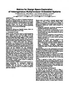
2. A Pattern-Based Software Development Method Our pattern-based software development procedure is based on Jackson’s problem frames approach 9 . However, we limit ourselves to provide only the instances of the problem frames (or the variants thereof) and not the problem frames themselves. The method consists of the following four steps: (1) Understand the problem situation After investigating the problem domain and identifying its current shortcomings, relevant domain knowledge is collected, and the system mission together with the corresponding requirements are recorded, as shown in Table 1. Domain knowledge (consisting of facts F and assumptions A) and requirements R (describing the system to be developed in its environment) are collected for detailing the system mission (SM). The given problem situation is structured by a context diagram, which represents the desired system, shown in Figure 1. It represents the overall problem situation. A context diagram covers the domain knowledge and the requirements of Table 1 by corresponding domains (boxes) and their interactions (shared phenomena at labeled interfaces). The machine domain (indicated by two vertical stripes) represents the software we are going to build. SM
A text-message-based communication platform shall be developed, which allows multi-user communication via private I/O-devices.
R1 R2 R3 . . . F1 A1
Users can phrase text messages, which are shown on their private display. Users send their phrased text messages to participate in the chat. Sending text messages changes the chat represented on the users’ display. ... Users communicate in a local network. Users follow the course of the chat on their private display. Table 1. Initial Set of Requirements and Domain Knowledge for a Chat Application
(2) Decompose overall problem into simple subproblems The requirements guide a knowledge-based decomposition of the overall problem that is represented by a context diagram into several simple subproblems. A simple subproblem is represented by a problem diagram, which expresses what the subproblem is about by referring to the involved domains and related shared phenomena. These subproblem representations together with the given domain knowledge suffice to derive a software specification describing the interface behavior of the machine. Figures 2 and 3 represent two simple subproblems for requirements R2 and R3. a a Figures
2 and 3 are explained in more detail in Section 3.
January 16, 2008
4
12:55
WSPC/INSTRUCTION FILE
ws-ijcis
Isabelle Cˆ ot´ e, Maritta Heisel, Ina Wentzlaff
text message
a d network
e
chat application b
b
a
user
c d
c
e
: {phraseTextMessage, sendTextMessage} : {showTextMessage} : {readDisplay} : {editTextmessage, MessageText} : {distributeTextMessage, pickUpTextMessages}
display
Fig. 1. Context Diagram for a Chat Application
(3) Fit subproblems to (variants of) problem frames When using a pattern-based development method, the subproblems are classified by instantiating suitable problem patterns, called problem frames (PF) 9 . These are patterns categorizing software development problems into problem classes during the analysis phase. Thus, each problem frame represents a problem category, which can be linked to patterns of a corresponding solution class. Via analogies, they can be related to patterns of software design 3,4,11 , resulting in a smooth transition from requirements engineering documents into design artifacts 12 . (4) Instantiate corresponding architectural and design patterns Finally, we make use of the problem/solution-pattern relationship 3 discussed in the previous Step (3) to derive a software design appropriate for the given problem situation documented in Steps (1) and (2). As an instance of a problem frame, each derived subproblem assigns values to its related architectural styles or design patterns. As a result, we obtain a more or less coarse-grained design (see Figures 4, 6, and 7) for each subproblem. These subproblem solutions can be used as a starting point for additional solution refinement, component deployment, or coding. Therefore, using a specific pattern in the analysis phase results in a predetermined choice of patterns in the design phase. If a subproblem fits to a problem frame (as in Figures 2 and 3), related architectural or design patterns (see Figures 4, 6, and 7) can offer a solution structure for it. In the following, we use design patterns such as Forwarder-Receiver 2 , which are comparable to architectural styles for developing software architectures. 3. Example: Developing a Chat System The starting point of our initial software development project is the system mission in Table 1. As described in Steps (1) and (2) of our development method, domain
January 16, 2008
12:55
WSPC/INSTRUCTION FILE
ws-ijcis
Pattern-based Exploration of Design Alternatives for the Evolution of Software Architectures
5
knowledge and requirements are collected, and a context diagram is set up (see Figure 1). The problem diagrams of Figures 2 and 3 represent two of the subproblems derived for the chat application. They refer to the requirements R2 and R3. c
text message
d
a b
b
chat application
network
e
R2
c d e
a
user
f
f
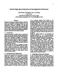
: US!{sendTextMessage} : CA!{distributeTextMessage} : TM!{MessageText} : “message text” : “transmit message” : “user input”
Fig. 2. “Message Forwarder” subproblem (instance of a variant of the commanded behaviour PF)
If a problem requirement such as R2 and R3 can be fitted to a problem frame, corresponding domains and shared phenomena for describing it in detail become identifiable. The dashed oval contains the requirements corresponding to the subproblems. The dashed lines indicate the relationships between these requirements and the different problem domains. An arrowhead pointing at a problem domain denotes a requirements constraint, which stipulates the development of a machine controlling the problem domain as stated in the requirements. The instantiated frame diagram supports the derivation of a specification, which is a technical description sufficient for developing the desired software. Here, the interfaces at the machine domain are of particular importance. They specify what services the desired software shall provide. In addition to the interfaces of a context diagram, in problem diagrams an abbreviation of the domain name (like US for user) is given. An exclamation mark at the labeled interfaces indicates which domain controls a shared phenomenon or a set of shared phenomena. An example for this is a: US!{sendTextMessage} in Figure 2. It means that the user initiates commands for sending chat text messages. b
network
c
a b
chat application
R3 a
display
d
c d
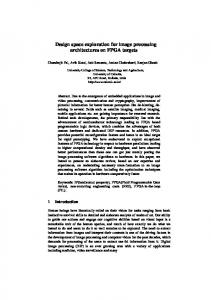
: CA!{showTextMessage} : NW!{pickUpTextMessages} : “obtaining message” : “update display content”
Fig. 3. “Message Receiver” subproblem (instance of information display PF)
As recommended by Step (3) of our pattern-based software development method, both subproblems of Figures 2 and 3 are instances of problem frames 9 . In our approach, problem frames and problem diagrams take the role of use cases known from Unified Modeling Language (UML) 13 , which are a means for
January 16, 2008
6
12:55
WSPC/INSTRUCTION FILE
ws-ijcis
Isabelle Cˆ ot´ e, Maritta Heisel, Ina Wentzlaff
requirements elicitation and problem decomposition. In contrast to use cases, problem frames and problem diagrams refer to their respective requirements explicitly. Furthermore, they represent necessary objects and their interactions in more detail, which enables a more coherent development. And in addition, they support our aim of an integrated pattern-based development procedure. Consequently, problem frames do not replace common development notations such as UML, but they extend them in a profitable way. First, we translate the subproblems into class diagrams (see classes chat application and network in Figure 4). This eases linking them to patterns of the software design, which in general are represented in UML notation. The resulting linkage is shown in Figure 4.
Forwarder sendMsg Peer n service receiveMsg
chat application sendTextMessage
marshal deliver sendMsg
...
Receiver receive unmarshal receiveMsg
...
network distributeTextMessage pickUpTextMessages
Fig. 4. Initial architecture based on the Design Pattern Forwarder-Receiver
The upper part of the class diagram shown in Figure 4 represents the ForwarderReceiver design pattern 2 . The two classes chat application and network are taken from the subproblems in Figures 2 and 3. They are related to the Forwarder-Receiver design pattern via analogy: The software we are going to build, namely the chat application is related to class Peer in Figure 4. The chat application takes the role of a Peer that provides services such as sendTextMessage, and network takes the role of Forwarder and Receiver for handling the reception of messages by pickUpTextMessage and their delivery through distributeTextMessage. In the following, the domain text message of Figure 2 and the domain display of Figure 3 are assumed to be part of the chat application or Peer. For the sake of simplicity, we will not consider them any further, because they have no architectural effects in our example. Figure 4 shows an initial software design, which is constructed entirely with patterns. Implementing this design results in a peer-to-peer chat system. For our example, we terminate the development process at this point.
January 16, 2008
12:55
WSPC/INSTRUCTION FILE
ws-ijcis
Pattern-based Exploration of Design Alternatives for the Evolution of Software Architectures
7
4. Considering Evolution through the Development Life Cycle To support evolution, we define a corresponding evolution step for each step of ´ Cinn´eide and Nixon 5 may the method described in Section 2. The work of O seem similar to our approach. However, we do not perform refactoring to introduce design patterns into a given system. Instead, our system is already composed of design patterns. Our evolution method consists of several steps, each providing evolution operators for the respective development phase. The evolution operators illustrate what the change is and how it should be carried out. They follow a common structure. This structure is a composition of different basic ingredients. Basic operations on artifact elements add
delete
Basic operations on patterns
modify
choose
Table 2. Basic operations
The first ingredient are basic operations, e.g. an addition, or a modification of artifacts to the already existing documentation. Table 2 shows an overview of the basic operations. The second ingredient are basic artifact elements and patterns. They denote exactly the element which is currently treated, e.g. a phenomenon, or domain, etc. Table 3 shows the relevant basic artifact elements. Basic artifact elements and patterns requirement domain knowledge
phenomenon domain
subproblem
architecture
problem frame
architectural style design pattern
Table 3. Basic artifact elements and patterns
We can now build an evolution operator by combining the different ingredients. For example, taking the ingredient add from the basic operations, and domain from the basic artifact elements results in the evolution operator add DOMAIN. This tells us what has to be done. Furthermore, every operator is equipped with a short description to illustrate how and under which circumstance it can be applied (for an example see the description of add DOMAIN below). We have selected the basic operations and artifacts in a way that no invalid combinations can occur. Using one evolution operator may imply the usage of another evolution operator in a subsequent step. These evolution operator dependencies, however, will not be detailed any further as this topic is beyond the focus of this work.
January 16, 2008
8
12:55
WSPC/INSTRUCTION FILE
ws-ijcis
Isabelle Cˆ ot´ e, Maritta Heisel, Ina Wentzlaff
In the following, we concentrate on illustrating those operators which are applied in our example. Changes to the original method introduced in Section 2 are indicated in bold face. The evolution operators are marked in bold face, as well. (1) Understand the new problem situation Evolution takes place when a change request is present. This request has different effects, depending heavily on whether or not requirements or domain knowledge are modified. Modifications of requirements and/or domain knowledge by evolution operators such as add REQUIREMENT or modify DOMAINKNOWLEDGE make it necessary to gain an understanding of the new circumstances. This may result in a modification of the context diagram, using evolution operators. In the following, we refer to new or changed requirements as evolution requirements eR and new or additional domain knowledge as aD. In general, domain knowledge D consists of facts F and assumptions A (D ≡ F ∧ A). The evolution operators relevant for this phase are: add DOMAIN A new domain has to be added to the context diagram. The eR and/or the aD introduce a new relevant domain. Relevant means that the domain is necessary to develop the specification for the machine. Usually, this implies that the new domain is directly connected to the machine domain. This domain has to be added to the context diagram. The new phenomena that occur have to be treated with add PHENOMENON or modify PHENOMENON. modify DOMAIN A domain contained in the context diagram has to be modified. Possible modifications are for example splitting or merging of domains. In contrast to add DOMAIN, the eR and aD do not necessitate a new domain in this case. However, they make it necessary to modify a given domain in the context diagram. This may occur when the eR and/or the aD are extended or changed, resulting in a possible application of add PHENOMENON. add PHENOMENON A new phenomenon is added to an interface of the context diagram. Whenever add DOMAIN is applied, it is also necessary to add new phenomena to the newly created interfaces between the added domain and the domains connected to it. It may also occur that a new phenomenon has to be added to an already existing interface (perhaps as a consequence of applying modify DOMAIN). modify PHENOMENON An existing phenomenon has to be modified in the context diagram, e.g. by renaming.
January 16, 2008
12:55
WSPC/INSTRUCTION FILE
ws-ijcis
Pattern-based Exploration of Design Alternatives for the Evolution of Software Architectures
9
The domains contained in the context diagram suffice to capture the new situation. The shared phenomena, however, have to be changed in order to handle the modified behavior derived from eR and/or aD. In some cases, it may also occur that neither domains nor shared phenomena are newly introduced. Then, no changes to the context diagram are necessary in Step (1), but the new requirements/domain knowledge may require changes in later steps. A reason for this is that at this stage, only the static aspects of the system and not the dynamic aspects are taken into account. The resulting context diagram now represents the new overall problem situation. (2) Decompose overall problem into simple subproblems, possibly modifying existing ones It is necessary to investigate the existing subproblems, applying evolution operators as necessary. The eR are the driving force behind this investigation, as they determine whether or not it is necessary to create a new subproblem or to adapt an existing one. Examples of evolution operators for this step are: modify SUBPROBLEM New domains and associated shared phenomena may be added to an existing problem diagram. This is possible if the eR references at most the same domains as the given subproblem. Conflicting requirements may occur at this point. However, resolving such conflicts will not be addressed here. add SUBPROBLEM Either the eR is assigned to a given subproblem, but the resulting subproblem then gets too complex. Hence, it is necessary to split the subproblem into smaller subproblems. Or the eR cannot be assigned to a given subproblem, and a new subproblem has to be created. For the next steps, only newly introduced and modified subproblems have to be taken into further consideration, as only these will undergo changes. The subproblems which have not been addressed in this step can be disregarded for now. They will only become relevant again in later steps, when the solutions of the subproblems are composed to the overall solution. (3) Fit subproblems to (variants of) problem frames and adjust problem frame instances The following evolution operator can be applied in this step: choosePROBLEMFRAME Each newly introduced subproblem is fitted into a problem frame by instantiating it according to the general procedure of Section 2. In addition, for each modified subproblem, it is checked whether its underlying problem frame is still valid, or whether another problem frame is now more appro-
January 16, 2008
10
12:55
WSPC/INSTRUCTION FILE
ws-ijcis
Isabelle Cˆ ot´ e, Maritta Heisel, Ina Wentzlaff
priate. The corresponding problem frame is then instantiated accordingly. (4) Modify and instantiate corresponding architectural and design patterns Comparable to evolution Step (2) driven by eR, this step is guided by aD. Evolution operators applicable in this step are: modify ARCHITECTURE Adapted subproblems, which still fit into already instantiated problem frames, can usually be incorporated into the given architecture without difficulties. chooseARCHITECTURALSTYLE/DESIGNPATTERN New subproblems or subproblems that fit to different problem frames than before lead to a new investigation of the solution. This investigation may result in a (re-)assignment of existing subproblems to new architectural styles or patterns. Furthermore, aD can cause a change in the problem/solution-pattern relation, resulting in a reallocation of subproblem elements to corresponding parts of solution patterns via new analogies. This fact distinguishes evolution scenario I in Section 5 from evolution scenario II in Section 6). In the subsequent sections, we illustrate the usage of these evolution operators by two evolution scenarios for our chat application. 5. Evolution Scenario I The starting point for this first software evolution scenario is a chat system as described in Section 3 for local communication (cf. F1 in Table 1), for example via a Bluetooth device as an implementation of the network domain. A limitation of such a chat application is that users are restricted to the range of their Bluetooth devices. This limitation has to be relaxed now. By evolution operator modify DOMAINKNOWLEDGE we obtain an extended fact aF1 about the application, see Table 4: Users communicate [...] via a wide area access network. However, there is also a constraint restricting the evolution procedure: The structure of the original application should be maintained. This constraint stresses the maximal possible reuse of artifacts of the existing system. Therefore, it will be necessary to maintain the existing architecture in its original form as far as possible. We now follow the procedure described in Section 4 for evolving the given chat system: (1) Understand the new problem situation Analyzing the change of domain knowledge results in the application of evolution operator add REQUIREMENT, which adds the evolution requirement eR5 to Table 4. It is not necessary to add a new domain into the context diagram. The set of existing phenomena suffices, as well. Therefore, it is not necessary to make any changes to the existing context diagram. It still looks as shown in Figure 1.
January 16, 2008
12:55
WSPC/INSTRUCTION FILE
ws-ijcis
Pattern-based Exploration of Design Alternatives for the Evolution of Software Architectures
R2 R3 . . . eR5
aF1
11
Users send their phrased text messages to participate in the chat. Sending text messages changes the chat represented on the users’ display. ... Users want to chat via long distances. Therefore it is necessary to pass the data from the local network to the wide access network (and vice versa). Users communicate in a local network, or via a wide area access network. Table 4. Changed Requirements and Domain Knowledge for Evolution Scenario I
b
network
c
a b
chat application
eR5 a
network
d
c d
: CA!{distributeTextMessage} : NW!{pickUpTextMessages} : “obtaining message” : “route message”
Fig. 5. “Message Dispatcher” subproblem (instance of a variant of the transformation PF)
(2) Decompose overall problem into simple subproblems and adapt existing ones Due to eR5 we apply the operator add SUBPROBLEM of Section 4 and create a new subproblem. The formerly used network is not able to provide a wide area access. Taking the above constraint into consideration, as well, we obtain the following new subproblem represented in Figure 5. We need to transfer the data from our Bluetooth network to another network, which will deal with passing the data to or receiving the data from the wide area access network. The other subproblems remain unchanged. (3) Fit subproblems to problem frames and adjust problem frame instances As we have created a new subproblem, the evolution operator choosePROBLEMFRAME described in Section 4 has to be applied. The new subproblem becomes an instance of a transformation problem frame variant accordingly. (4) Modify and instantiate corresponding architectural and design patterns By having a closer look at the new problem diagram in Figure 5, we see that what is performed by this subproblem can be characterized as a kind of dispatching. Now the evolution operator chooseARCHITECTURALSTYLE/DESIGNPATTERN has to be considered. While investigating ForwarderReceiver architecture for the subproblems given in Figures 2 and 3 we see that these problem diagrams stay untouched, and so does their corresponding architecture. To the newly created subproblem, we apply the operator chooseARCHITECTURALSTYLE/DESIGNPATTERN. As we know that we
January 16, 2008
12
12:55
WSPC/INSTRUCTION FILE
ws-ijcis
Isabelle Cˆ ot´ e, Maritta Heisel, Ina Wentzlaff
need a dispatcher, this leads us to the pattern of Client-Dispatcher-Server 2 , because a dispatcher is responsible for establishing a (wide area) connection between two parties. Another alternative could be the design pattern Proxy (see Section 7.3). However, we choose the first pattern, namely Client-DispatcherServer, to illustrate the evolution in this scenario. To satisfy the accompanying evolution constraint to reuse as many development artifacts as possible, we attach the Client-Dispatcher-Server to the already applied Forwarder-Receiver pattern, resulting in a hybrid design pattern. Here, we follow in general the pattern-oriented analysis and design (POAD) approach 15 . As shown in Figure 6, the new solution pattern for the added subproblem in Figure 5 can therefore simply be “plugged together” on the conceptual level with the existing one in Figure 4. By modify ARCHITECTURE new associations are created between the existing components of the architecture for incorporating the Client-Dispatcher-Server pattern. Forwarder Client sendMsg
marshal deliver sendMsg
Peer n
requests doTask connection sendRequest
requests services
returns result
service Server
Receiver receiveMsg
chat application sendTextMessage
receive unmarshal receiveMsg
acceptConnection registers runService accepts link receiveRequest
Dispatcher locationMap registerService unregisterService locateServer etablishes establishConnection connection getChannel
network distributeTextMessage pickUpTextMessages
Fig. 6. Evolved Class Diagram of the Chat Application (Hybrid Style)
The connection between the two solution patterns namely ForwarderReceiver and Client-Dispatcher-Server is realized through dependencies. We want to maintain the original patterns as much as possible. The class Forwarder and Client share the responsibility for sending some content or requests. Therefore, we can reuse Forwarder for implementing sendRequest of class Client. The same holds for the class Receiver, which is responsible for realizing the Server operation receiveRequest. The chat application and network class derived from our subproblem descriptions are related to the combined solution patterns via generalization/specialization relations. Their roles remain as discussed in Section 3, Fig-
January 16, 2008
12:55
WSPC/INSTRUCTION FILE
ws-ijcis
Pattern-based Exploration of Design Alternatives for the Evolution of Software Architectures
13
ure 4. In its role as a Dispatcher, the chat application uses its reference to network for controlling its message handling. Interesting is the role of the network, because it is part of all three subproblems. For the subproblems in Figures 2 and 3, the network is responsible for providing the Forwarder/Receiver functionality. For the subproblem in Figure 5, it implements Dispatcher operations. For the Dispatcher the network connects the different chat peers via long distances, whereas each Peer is a Client as well as a Server communicating via a Forwarder-Receiver mechanism. It is clearly visible that in this first evolution scenario the modification of aF1 and the addition of eR5 resulted in the creation of a new subproblem. Because of this new subproblem, it was necessary to make a new design decision. Considering the given constraint, the decision leads us to an extention of the existing Forwarder-Receiver architecture to a hybrid Forwarder-Receiver/Client-Dispatcher-Server style. Alternatives to this decision are discussed in Section 7.3. 6. Evolution Scenario II The second evolution scenario is based on the results of Section 5. With the current chat application it is possible to communicate with other users via Bluetooth or a network providing wide area access. The devices used so far are general purpose computers. Mobile devices such as portable phones or personal digital assistants (PDA) are not supported yet. This describes the limitation that we remove in this second evolution scenario: The usage of portable devices should be possible, as well. Once more the evolution steps described in Section 4 are applied: R2 R3 . . . eR5 aF1 aF2
Users send their phrased text messages to participate in the chat. Sending text messages changes the chat represented on the users’ display. ... Users want to chat via long distances. Therefore it is necessary to pass the data from the local network to the wide access network (and vice versa). Users communicate in a local network, or via a wide area access network. The devices used are general purpose computers as well as portable phones and personal digital assistants (PDAs). Table 5. Changed Requirements and Domain Knowledge for Evolution Scenario II
(1) Understand the new problem situation New domain knowledge is added due to evolution operator add DOMAINKNOWLEDGE resulting the additional fact aF2 in Table 5. This new fact describes hardware constraints referring to the machine domain. No additional requirements are necessary.
January 16, 2008
14
12:55
WSPC/INSTRUCTION FILE
ws-ijcis
Isabelle Cˆ ot´ e, Maritta Heisel, Ina Wentzlaff
Therefore, the context diagram remains unchanged, even though new domain knowledge has been introduced. The reason is that aF2 influences internal characteristics of the machine, and not its behavior. These characteristics, however, cannot be described by a context diagram. (2) Decompose overall problem into simple subproblems and adapt existing ones The distribution of the overall problem situation into subproblems stays unchanged, because the requirements do not change. (3) Fit subproblems to problem frames, and adjust problem frames instances No changes have to be performed in this step, because no changes were performed in the previous step. (4) Modify and instantiate corresponding architectural and design patterns This step is the nontrivial one in this scenario, because here the effect of the newly introduced domain knowledge becomes visible. Fact aF2 influences the decision which pattern to select in the solution space. Mobile devices such as PDAs or mobile phones do not possess the same resources as general purpose computers do. The new fact thus imposes a constraint on the selection of design patterns and architectural styles. Here, it leads to a re-design of the present architecture by means of the evolution operator chooseARCHITECTURALSTYLE/DESIGNPATTERN.
Client requests doTask connection sendRequest requests services
returns result Server
acceptConnection registers runService accepts link receiveRequest
Dispatcher locationMap registerService unregisterService locateServer etablishes establishConnection connection getChannel
network chat application sendTextMessage
distributeTextMessage pickUpTextMessages
Fig. 7. Evolved architectural design based on Client-Dispatcher-Server
The new domain knowledge enforces a reorganization of the given subproblems, resulting in a different choice of architectural style or design pattern out of
January 16, 2008
12:55
WSPC/INSTRUCTION FILE
ws-ijcis
Pattern-based Exploration of Design Alternatives for the Evolution of Software Architectures
15
the related solution class. For our example, the three subproblems are matched with the Client-Dispatcher-Server pattern only (cf. Figure 7). The former Forwarder and Receiver components are merged with the client and server components. The chat application now consists of two parts namely, a Server and a Client part. The functionality formerly represented by the Peer are now partially realized by the Server and Client classes, respectively. In the first evolution scenario, we had to deal with a constraint. This constraint is still present in the second scenario, however, in a weakened form: all the subproblems not involved in the data transmission/reception remain unchanged, and the development documents related to them can be reused as is. In this second scenario, adding domain knowledge in form of aF2 results in a complete restructuring of the architecture. The reason is that the new domain knowledge leads to a different matching of subproblems to architectural patterns, resulting in a new, more appropriate and simpler architecture. 7. Generating and Choosing Design Alternatives The architectural solutions presented in Sections 5 and 6 are not the only existing ones. Several different design alternatives exist that all form valid solutions for our subproblems considered in Figures 2, 3, and 5. In this section we discuss some of these alternatives that we generated based on commonly known patterns in the context of software evolution. 7.1. The original architectural design As mentioned in the last paragraph of Section 2, we consider a set of subproblems that contribute to a common architectural solution. To discuss design alternatives we need to take into account how the different subproblems are related. We make use of a context-free grammar like notationb to represent the subproblem relationships. By means of this grammar we identify collaborations of functions that should be maintained and that decide on the deployment of components for structuring the architecture. The grammar makes use of: • • • • •
terminal symbols: names of (relevant) subproblems non-terminal symbols: given in brackets, such as sequential subproblem relationships: by concatenation of symbols alternative subproblem relationships: represented by | parallel subproblem relationships: represented by ||
In addition parentheses can be introduced to emphasize ordering relations. b Note,
that the presented grammar does not illustrate the complete grammar covering all subproblems. It only provides an excerpt for the subproblems discussed here.
January 16, 2008
16
12:55
WSPC/INSTRUCTION FILE
ws-ijcis
Isabelle Cˆ ot´ e, Maritta Heisel, Ina Wentzlaff
The following grammar represents the subproblem relationships relevant for our initial peer-to-peer system (cf. Section 3). The architecture in Figure 4 is based exclusively upon the Forwarder-Receiver pattern. It illustrates a solution for the two subproblems named “Message Forwarder” (cf. Figure 2) and “Message Receiver” (cf. Figure 3). The grammar below shows that the two subproblems act in parallel on a common peer application. Thus, the peer application can forward and receive messages in parallel. ::= (MessageForwarder || MessageReceiver) For the evolution task we show how the subproblem relationships represented through the grammar are affected by the evolution operators and how the modifications to the grammar result in changes in the architecture. Peer Application Registry BT Forwarder Peer Receiver
BT
Fig. 8. Composite Structure Diagram of a Peer Application
In Figure 8 we summarize the peer-to-peer architecture of Figure 4 in a composite structure diagram known from UML 13 . By the example of the component Registry, which is part of the original Forwarder-Receiver pattern, but for the sake of simplicity was not mentioned so far, we show how the given architecture evolves. Registry is used by Forwarder. The Registry contains the addresses of all participating peers. In this initial development scenario the peers communicate among each other locally via Bluetooth devices. Thus, the range of peers is restricted and the number of participants is limited, because of this environmental constraint (capacity of Bluetooth device). The architectural solution presented in Figures 4 and 8 is a rich or fat Peer Application, whose major responsibilityc is implemented by the Forwarder component, namely: locating and handling a list of all participants (Registry), and managing message broadcast (via the operation deliver) to other peers using interface BT. 7.2. Design Alternatives for Evolution Scenario I The application of the evolution operators given in Section 4 affect the two subproblems and their relationships represented by the previously given grammar (cf. Section 7.1) and thus bias their corresponding architecture. c collaboration
of different functionality for accomplishing a common task
January 16, 2008
12:55
WSPC/INSTRUCTION FILE
ws-ijcis
Pattern-based Exploration of Design Alternatives for the Evolution of Software Architectures
17
Evolution scenario I in Section 5 incorporates a new requirement eR5 (cf. Table 4) that demands for a wide-area network access. This evolution requirement cannot be covered by the original network as the communication range of a Bluetooth (BT) device is restricted. Here, we assume that a wireless local area network (W-LAN) is used to overcome this limitation. Network
W−LAN
Bluetooth
Fig. 9. Multiple roles of the network domain
The solution presented in Section 5 for the evolution scenario I introduces a new subproblem (applying evolution operator add SUBPROBLEM, followed by evolution operator choosePROBLEMFRAME) named “Message Dispatcher” (see Figure 5) to handle the general network access. This subproblem can be further decomposed into a subproblem that converts Bluetooth signals to W-LAN signals and vice versa where Bluetooth and W-LAN are a specialization of the network domain (cf. Figure 9). An additional constraint is to maintain the original (peer-topeer) architecture of the chat application. The evolution operators applied so far affect the subproblem relationships as follows: ::= (MessageForwarder || MessageReceiver) || (MessageForwarder || MessageReceiver) ::= (MessageDispatcherBT /W −LAN || MessageDispatcherW −LAN/BT ) We can see that the initial grammar in Section 7.1 and this new one have the first line in common. This tells us that the local communication via Bluetooth remains untouched. Additionally, sequential and parallel subproblem relationships are used to extend the original grammar. The complete network access is directed via W-LAN (second line). This is reflected by a changed external interface W-LAN of Peer Application in Figures 10 and 11 in contrast to Figure 8. As mentioned before, a new subproblem “Message Dispatcher” is introduced via evolution operators add SUBPROBLEM and choosePROBLEMFRAME. As this new subproblem and the existing subproblem “Message Forwarder” are related sequentially, we introduce a new non-terminal symbol, namely to handle this relationship. The purpose of this third line of the grammar is to deal with the transmission of data between local and wide-area network for establishing communication between the different peers. The modified grammar results in the application of the evolution operator(s) chooseARCHITECTURALSTYLE/DESIGNPATTERN and/or modify ARCHITECTURE in the subsequent evolution steps. However, all subproblems given in the new grammar are still implemented in one application.
January 16, 2008
18
12:55
WSPC/INSTRUCTION FILE
ws-ijcis
Isabelle Cˆ ot´ e, Maritta Heisel, Ina Wentzlaff
The changes made in the subproblem relationships facilitate the evolution task. Driven by evolution operators, the grammar provides hints on (subproblem specific modularization of functionality that triggers) activities for changing the architecture. These activities may involve re-engineering techniques. Peer with Dispatcher Application Registry BT
Client
Forwarder Peer
BT
Dispatcher
W−LAN
Server
Receiver
Adapter
Fig. 10. Extending a Peer Application by a Dispatcher for Alternative I
Alternative I: Forwarder-Receiver and Client-Dispatcher-Server This design solution chosen in Section 5 is a hybrid architecture. Figure 10 shows the composite structure diagram corresponding to the architecture given in Figure 6. We can see that the responsibilities have been re-organized within the Peer Application. The Client-Dispatcher-Server pattern is plugged to the existing components via “use-relations”. The Dispatcher component takes on the responsibility of maintaining the participants list. This is indicated by the changed use-relation of Registry, which shifts from the Forwarder to the Dispatcher. In addition, the Dispatcher component converts the Bluetooth communication into a W-LAN communication. In this role, the Dispatcher also implements the responsibilities of an Adapter. The Peer with Dispatcher Application is now in the position to fulfill eR5: The result enables extended communication capabilities. Peer with Adapter Application Registry Forwarder
BT
Receiver
BT
Peer
Adapter
W−LAN
Fig. 11. A Peer Application utilizing an Adapter for Alternative II
Alternative II: Forwarder-Receiver and Adapter A straightforward (probably more intuitive) solution for the new requirement eR5 is to introduce a new component which simply converts signals from Bluetooth to W-LAN and vice-versa. This would then lead us to the Adapter design pattern 7 . All
January 16, 2008
12:55
WSPC/INSTRUCTION FILE
ws-ijcis
Pattern-based Exploration of Design Alternatives for the Evolution of Software Architectures
19
other responsibilities within the Peer, especially the Forwarder-Registry relationship, remain unaffected. The adapter, which is responsible for the conversion task, is simply connected to the Bluetooth interface (cf. Figure 11). The presented design Alternative I and Alternative II are based upon the assumption that the Bluetooth communication is substituted or encapsulated by the W-LAN. This assumption is introduced by the parallel subproblem relationship of MessageForwarder and MessageForwarder. In addition, it is reinforced by the domain knowledge about the limited communication range of the Bluetooth device, which results in a changed external interface for the two alternative composite structure models. The following Alternative III and Alternative IV consider the case, when the grammar specifies an alternative relationship between MessageForwarder and MessageForwarder. ::= (MessageForwarder || MessageReceiver) | (MessageForwarder || MessageReceiver) ::= (MessageDispatcherBT /W −LAN || MessageDispatcherW −LAN/BT ) Alternative III: Forwarder-Receiver and Strategy Another architectural solution is the usage of the Strategy design pattern 7 , working as a switch. The switch selects between either the Bluetooth or the W-LAN network, depending on whether local or wide area access is desired (in Figure 12, disregarding the use-relation of Adapter for this design alternative). This solution is only possible if both protocols are supported by the device that holds the peer. Otherwise an adapter must be implemented (see the following Alternative IV). Alternative IV: Forwarder-Receiver, Strategy, and Adapter This design alternative is similar to Alternative III. The difference is that it deals with the situation that the device holding the Peer Application does not support both communication protocols. Hence, it is necessary to add an Adapter that takes over the BT/W-LAN conversion provided through the corresponding use-relation in Figure 12. The Strategy then selects between the existing BT or the adapted WLAN communication variant. The external interface of the Peer Application provides local BT, as well as wide W-LAN access. All the alternatives presented in this section only make changes within a Peer Application. They characterize an equivalence class of architectural design solutions with monolithic applications (fat peers) and a decentralized communication structure. The effort needed for the evolution tasks depends on the degree of modularization. As a result, combining the Forwarder-Receiver architecture with a ClientDispatcher-Server style requires more engineering experience and understanding of the given system, than attaching a simple adapter. But, knowing the responsibilities of the Dispatcher component eases the shift of functionality demanded by further evolution tasks, as we discuss next.
January 16, 2008
20
12:55
WSPC/INSTRUCTION FILE
ws-ijcis
Isabelle Cˆ ot´ e, Maritta Heisel, Ina Wentzlaff
Peer with Strategy (and Adapter) Application Registry
Forwarder Forwarder
Peer
Strategy
Adapter
Receiver Receiver
BT W−LAN W−LAN BT
Fig. 12. Peer with Strategy (and Adapter) for Alternative III/IV
7.3. Design Alternatives for Evolution Scenario II The evolution scenario II in Section 6 incorporates a hardware constraint (devices with limited capacity/connectivity are used) that results in the need to make the peers slimmer. In this case it is not sufficient to only re-organize the functionality by shifting them around within the peer. This time it is necessary to outsource them to another entity, located outside of the peer. We consider the given subproblems and derive a new subproblem out of the given “Message Dispatcher” that handles several peers communicating via W-LAN by applying evolution operator add SUBPROBLEM. A new non-terminal symbol is added to the grammar for handling the entity that holds the outsourced responsibilities. The grammar for describing the subproblem relationships is: ::= (MessageForwarder || MessageReceiver) ||d (MessageForwarder || MessageReceiver) ::= (MessageDispatcherW −LAN/BT || MessageDispatcherBT /W −LAN ) ::= MessageDispatcherW −LAN/W −LAN The outsourced responsibilities (given by the part of the above grammar) do not affect the Adapter functionality of the peer, but the parts related to the participants list (Registry) and thus the management of message broadcasting. Each of the mentioned design alternatives in Section 7.2 can be used as basis for this second evolution scenario II. Depending on the starting point, more or less effort is needed to evolve the system, though. Alternative A: Outsourcing parts of the dispatcher The basis for this design alternative is the hybrid architectural solution presented in Section 5 as well as in Alternative I, cf. Section 7.2. The functionality of the dispatcher located within the peer is split by applying the evolution operad Here, we use a parallel subproblem relationship || for design A and an alternative relationship | for design B. However, the main emphasis of this Section 7.3 is the reallocation of Peer Application functionality related to the part of this grammar.
January 16, 2008
12:55
WSPC/INSTRUCTION FILE
ws-ijcis
Pattern-based Exploration of Design Alternatives for the Evolution of Software Architectures
Peer with outsourced part of Dispatcher Application
Dispatcher−"server" Application
BT Client
Forwarder Peer
Dispatcher− BT
Receiver
21
Server
Part4Adapter
W−LAN
1:1
W−LAN 1:n
Dispatcher− Part4− Registry
Access Control
Adapter
Registry
Fig. 13. A Peer with outsourced part of the Dispatcher for Alternative A
tor add SUBPROBLEM. In Figure 10 the Dispatcher component is responsible for Adapter and Registry tasks; now these functionality are separated into a part responsible for establishing a BT/W-LAN connection via an adapter named DispatcherPart4Adapter and a part responsible for managing the participating peers as well as broadcasting messages (which refers to Registry, cf. use-relation of DispatcherPart4Registry) in Figure 13. The functionality that implements Registry responsibilities is transferred into a new application named Dispatcher-“server” Application running on a “server”e outside the peer. This “server” is from now on responsible for locating other peers, handling the list of participating peers, and broadcasting the data between them. The Dispatcher within the Peer Application is transformed into a simple adapter used for converting the signals from one network to the other. Now a Peer Application only knows the location of its Dispatcher-“server”; it is not directly connected to all participating peers anymore for establishing a connection. We achieve a 1 : 1 connection by this design alternative for each peer and thus take the hardware constraint (limited capacity of devices) into account. This is in contrast to the previous hybrid architectural solution where each peer has its own dispatcher (and thus a 1 : n connection, where n is the number of participating peers, cf. Figure 13). Usually the only responsibility of a Dispatcher-“server”-Application is related to the Registry that is maintaining the participants list and establishing connections. If a connection link is set up, broadcasting of messages will be managed again directly between participating peers, which restores a 1 : n communication between them. We discuss how to overcome this drawback, when the responsibilities of a dispatcher are extended to a proxy as discussed in the Alternative B. However, the currently discussed alternative represents no exclusive peer-to-peer architecture anymore such as given in Sections 7.1 and 7.2. It moves to a client-server variant, where a Peer Application implements the subproblems related to and and the Dispatcher-“server”-application implements the subproblems related to .
e an
independent node that is not a peer itself
January 16, 2008
22
12:55
WSPC/INSTRUCTION FILE
ws-ijcis
Isabelle Cˆ ot´ e, Maritta Heisel, Ina Wentzlaff
Alternative B: Forwarder-Receiver, Strategy, Adapter, and Proxy A peer-to-peer architecture that is extended by strategy and adapter such as in Alternative IV of evolution scenario I in Section 7.2 could be the starting point for the alternative presented here, see Figure 12. A design solution comparable to Alternative A for this second evolution scenario II is achievable by extending the dispatcher responsibilities to a Proxy 7 . In general, a proxy is more powerful than a dispatcher. In contrast to a dispatcher, a proxy does not only establish connections, it also provides Access Control and manages these connections. Thus, a proxy is a dispatcher with extended responsibilities. It can provide filters for establishing only permitted connections or otherwise refuse to set up a connection, cf. Figure 14. Proxy Application
Peer with Strategy (and Adapter) Application
Registry
Registry
Forwarder
local
Forwarder Peer
Strategy
Adapter
Receiver Receiver
BT
wide
W−LAN
1:1 1:n W−LAN
W−LAN
Proxy
1:n 1:1
BT Access Control
Fig. 14. A Peer connected via a Proxy for Alternative B
In contrast to Alternative A in Figure 13 the connection of a peer to a proxy remains 1 : 1 (for maintaining the participants list and broadcasting messages). The Proxy Application becomes a central node for the peers’ communication. The variants of this Alternative B differ in their use of the proxy. For example, the Bluetooth communication is additionally directed via proxy (where Registrylocal is allocated to proxy) or the implementation of Access Control varies (user login, passwd, etc.). However, treating the additional subproblems related to access control is out of the scope of this work. As in Alternative A, we shift functionality out of the peer into another entity. This time, however, the shifting results in a two-tier architecture with a slimf client (peer). The alternatives presented in this section require to shift responsibilities outside a Peer Application. It is necessary to extract functionality and transfer them to an extra entity. Therefore, considering subproblem relationships is of value. The design alternatives of this section characterize an equivalence class of architectural design solutions that results in slim client (peer) applications and a centralized communication structure (two-tier system). 7.4. Discussion of Design Alternatives In Sections 7.2 and 7.3 we have discussed several alternative architectures, which all are valid solutions to the same development problem. All alternatives are based f with
respect to the set of subproblems that we have taken into account
January 16, 2008
12:55
WSPC/INSTRUCTION FILE
ws-ijcis
Pattern-based Exploration of Design Alternatives for the Evolution of Software Architectures
23
on commonly known patterns for the design phase. Evolution operators guide the systematic generation of diverse architectures. In our example, these design alternatives vary between exclusive peer-to-peer or client-server systems, and some hybrid variants in between. Choosing among these architectures strongly depends on the properties of the deployment environment. That environment constrains the allocation of coherent functionality (related to some responsibilities) and thus their organization into a structure 1 , which is named architecture. By means of problem frames and a grammar for representing subproblem relationships, we are in the position to identify components and their collaborations to fulfill a specific task. These architectural building blocks are assembled according to certain (extra-functional) conditionsg , which require an in-depth understanding of the environment (domain knowledge) into which the resulting software is integrated. We have shown that diverse architectural alternatives are possible, but not all structures are applicable for balancing the core-functionality with the given environmental conditions. Software evolution causes changes on requirements or properties of the deployment environment. For capturing the evolution effects, we introduced operators that guide systematic changes on the development documents to meet the changed conditions. The evolution task (especially the modification of the architectural structure) is accomplished by pattern-based (re-)engineering activities. 8. Conclusion and Future Work We have introduced a pattern-based development method, incorporating evolution in each step, and driven by evolution operators. With this method, it is possible to perform software evolution systematically whenever new requirements or changes in the application environment occur. Through a chat application example, we have shown the usage of our method. We illustrated how a system evolved from a straight peer-to-peer architecture via a hybrid architecture to a client-dispatcher-server system. This evolution is achieved by applying evolution operators. They allow for identifying those development documents, which have to undergo change. Thus, they provide guidance for performing the necessary modifications in phases to come. This approach enables us to perform a systematic rework on the affected development documents by means of patterns. We have shown that it is possible to link the artifacts of the analysis phase to the artifacts of the design phase. Therefore, changes in the analysis help to perform an analogous procedure in the design phase. Our method does not intend to replace existing methods or notations. It rather extends them by a goal-oriented, pattern-based approach resulting in coherent and precise specifications. The method does not postulate a dogmatic approach, always g such
as software quality aspects, whose evaluation always depends on the properties of the deployment environment
January 16, 2008
24
12:55
WSPC/INSTRUCTION FILE
ws-ijcis
Isabelle Cˆ ot´ e, Maritta Heisel, Ina Wentzlaff
resulting in exactly one unique solution. We intend to constrain the possible solutions (design space) to provide a small, most promissing set of patterns useful for solving the problem. Also non-functional requirements can be treated with our approach: If these quality aspects are specified in the problem frames (such as HCI Frames 14 or using Security Problem Frames 8 ), they will lead to solutions that address these nonfunctional issues, see evolution scenario I in Section 5. Additionally, non-functional aspects that are manifested in domain knowledge can be covered, see evolution scenario II in Section 6. Furthermore, we illustrated that it is possible to obtain several design alternatives, moving between the boundaries of an exclusive peer-to-peer and an exclusive client-server architecture. These alternatives are generated by applying the evolution operators and by taking environmental circumstances, as well as knowledge about different architectural styles into account. Selecting among the different alternatives is guided by the environment the software will be deployed in. Hence, the quality (extra-functional) requirements influence which of the present alternatives is the most suited one and should therefore be chosen as architectural solution. In summary, the advantages of our approach are the following: • Our method is pattern-to-pattern, integrating evolution. Hence, it has all assets that come with the use of patterns, in particular, reuse of established analysis and design knowledge in a variety of application domains. • Our evolution operators provide guidance concerning pattern selection and transformation. They help to adapt the development problem and to find new solutions if necessary. • Extra- or non-functional requirements can be treated, as well. • Our method supports setting up different design alternatives and choosing among them. Currently, we are working on a formalization of the problem frames. For that purpose, we are building a formal metamodel. This model is equipped with integrity conditions to ensure the validity of a frame with respect to the metamodel. It is planned to create an Eclipse 6 plug-in for the metamodel. The plug-in will work as an editor to create valid frame diagrams in the context of our metamodel. The metamodel will also serve as a basis for investigating which of the evolution operators can be formalized and incorporated into it. In a further step, the plug-in will be extended to allow for an automation of the formalized evolution operators. In the future, we also plan to analyze the effects of domain knowledge within the evolution process in more depth. Additionally, we plan to examine the impact of the change in the architectural structures to later documents of the software life cycle, especially considering the source code. Furthermore, we intend to put stronger emphasis on distinguishing internal and external quality aspects and how they are successfully covered by our method. It is also planed to have a detailed look at the decompositions and compositions of the subproblems with respect to the
January 16, 2008
12:55
WSPC/INSTRUCTION FILE
ws-ijcis
Pattern-based Exploration of Design Alternatives for the Evolution of Software Architectures
25
architecture, which would also contribute to investigate the scalability of problem frames. We further will investigate which problem frames should be related to which architectural design patterns or architectural styles for completing our method. Acknowledgments We want to thank the anonymous reviewers for their constructive comments on a previous version of this work, which especially contributed to the improvement of our evolution operators. References 1. L. Bass, P. Clements, and R. Kazman. Software Architecture in Practice. AddisonWesley Professional, 1997. 2. F. Buschmann, R. Meunier, H. Rohnert, P. Sommerlad, and M. Stal. Pattern-Oriented Software Architecture: A System of Patterns. John Wiley & Sons, 1996. 3. C. Choppy, D. Hatebur, and M. Heisel. Architectural Patterns for Problem Frames. IEE Proceedings - Software, 152(4):198–208, 2005. 4. C. Choppy and M. Heisel. Use of Patterns in Formal Development: Systematic Transition From Problems to Architectural Designs. In Recent Trends in Algebraic Development Techniques, 16th WADT, Selected Papers, pages 205–220. Springer, 2003. ´ Cinn´eide and P. Nixon. Automated Software Evolution towards Design Pat5. M. O. terns. In IWPSE ’01: Proceedings of the 4th International Workshop on Principles of Software Evolution, pages 162–165, New York, NY, USA, 2001. ACM Press. 6. T. E. Foundation. Eclipse - an open development platform, 2007. http://www.eclipse.org. 7. E. Gamma, R. Helm, R. Johnson, and J. Vlissides. Design Patterns – Elements of Reusable Object-Oriented Software. Addison Wesley, 1995. 8. D. Hatebur, M. Heisel, and H. Schmidt. Security Engineering using Problem Frames. In Proc. of the Int. Conference on Emerging Trends in Information and Communication Security (ETRICS), volume 3995/2006, pages 238–253. Springer, 2006. 9. M. Jackson. Problem Frames. Analyzing and Structuring Software Development Problems. Addison-Wesley, 2001. 10. S. L. Pfleeger. Software Engineering: Theory and Practice. Prentice Hall, 2001. 11. L. Rapanotti, J. G. Hall, M. A. Jackson, and B. Nuseibeh. Architecture-driven Problem Decomposition. In Proceedings of the 12th IEEE International Requirements Engineering Conference (RE’04), Kyoto, Japan, 2004. IEEE. 12. H. Schmidt and I. Wentzlaff. Preserving Software Quality Characteristics from Requirements Analysis to Architectural Design. In Proceedings of the 3rd European Workshop on Software Architectures (EWSA’06), Nantes, France, 2006. Springer. 13. UML Revision Task Force. OMG Unified Modeling Language: Superstructure, 2007. http://www.omg.org. 14. I. Wentzlaff and M. Specker. Pattern-based Development of User-Friendly Web Applications. In Workshop Proceedings of the 6th International Conference on Web Engineering (ICWE), New York, NY, USA, 2006. ACM Press. 15. S. M. Yacoub and H. H. Ammar. Pattern-oriented Analysis and Design: Composing Patterns to Design Software Systems. Addison-Wesley, 2003.