The discharge energy for this operating point was about 130 J. ..... printer heads. Here the liquid is .... amount of stored energy and the amount mass that.
Performance Characterization of a High Efficiency Gas-Fed Pulsed Plasma Thruster∗ J.K. Ziemer†, E.A. Cubbin‡ and E.Y. Choueiri§ Electric Propulsion and Plasma Dynamics Laboratory (EPPDyL) MAE Dept. Princeton University Princeton, New Jersey 08544 Daniel Birx Science Research Laboratory Inc., Sommerville MA 02143 AIAA-97-2925¶
Abstract
thrusters was solved using a scheme based on an allsolid-state modulator with IGBT commutation that allows high repetition rate pulsing of the discharge (5000 pps) developed at SRL Inc. The scheme results in a mass utilization efficiency close to 100%.
We present a characterization of the performance of a recently developed gas-fed pulsed plasma thruster (GF-PPT) at low discharge energies (≤5 J). The impulsive thrust measurements were made using EPPDyL’s high-accuracy interferometric microthrust stand. The thruster is best suited for small satellite applications and is operated in an unsteady pulsed mode (3 µs/pulse). It is the result of a series of design iterations aimed at achieving the highest thrust efficiencies for unsteady electromagnetic acceleration at low discharge energies. The use of advanced nonlinear magnetic switching technology, which insured a total system inductance of 3-4 nH, combined with an electrode geometry and radial gas injection that favor low profile losses, yielded a total efficiency of 50% at 5 J with argon (at an impulse bit of 32 µNs and a mass bit of .2 µg/shot). This is the highest measured efficiency ever reported for a PPT at this low energy level. Moreover, the low mass utilization efficiency problem that plagued previous gas-fed pulsed
1
Introduction
There has been a considerable surge of interest in pulsed plasma thrusters (PPTs) over the past four years due to their unique capability of providing high specific impulse at arbitrarily low spacecraft bus power. This makes the PPT a particularly suitable propulsion option for today’s power-limited small satellites[1]. Receiving most attention is the ablative PPT (or APPT) which commonly uses Teflon for propellant. The APPT, in addition to its high Isp capability, has some unique advantages stemming from the stability, simplicity and the ease of handling of its solid propellant. While considerable development of the APPT concept was done in the 1970’s, modern research and development efforts on APPTs are aimed at applying recent developments in related technologies to improve their performance. It has so far proven difficult to make the APPT efficient at low discharge energies and measured efficiencies are typically well below 10% for energy levels at and below 5 J. Historically, gas-fed PPTs (GF-PPTs) are the progenitors of their ablative counterparts. An active re-
∗ Research supported by Science Research Laboratory Inc. through a NASA-JPL SBIR. Portion of the work was also supported by the Air Force Office of Scientific Research, grant number: F49620-95-1-0291. † Graduate Student, Research Assistant. Member AIAA. ‡ Graduate Student, Research Assistant. Member AIAA. § Chief Scientist at EPPDyL. Assistant Professor, Applied Physics Group. Senior Member AIAA. ¶ Presented at the 33rd AIAA Joint Propulsion Conference, Seattle, WA, July 6-9, 1997.
1
2
ZIEMER, CUBBIN, CHOUEIRI & BIRX: HIGH-EFFICIENCY PPT PERFORMANCE
search period on GF-PPTs in the early sixties[2] lead to significant performance improvements. By 1966 a milestone was reached at the General Electric Space Science Laboratory[3] with a GF-PPT operating with xenon at an Isp of 5000 s and an efficiency of 57%. The discharge energy for this operating point was about 130 J. GF-PPTs, however, are handicapped by a low mass utilization efficiency due to the fact that the pulse duration is much smaller than the time response of available space-qualified fast acting gas valves. This handicap was one the impetuses that lead to research and development work on the ablative PPT. With the present revival of interest in the APPT, it is worthwhile to reconsider the gas-fed variant of this technology in light of the various technologies that are now available. This is especially justified by the fact that each of these two options boasts some advantages not shared by the other. Both the APPT and the GF-PPT share the following advantages:
• much wider range of achievable specific impulses (with fixed geometry),
• High specific impulse propulsion (hence large mass savings) at very low bus powers. (Power levels well below those required for most other EP systems).
Due to the above advantages and the fact that only the APPT has been considered in recent years, a generation of GF-PPTs was developed under a NASAJPL SBIR at SRL Inc. and studied at EPPDyL. Due to JPL’s projected propulsion requirements and the growing importance of small and micro-satellites, the focus is, unlike in the 1960’s, on low discharge energies. There are three consecutive research goals:
• Small, precise and repeatable impulse bits • Discharge circuit simplicity (single capacitor) • Simple thruster design that enhances reliability • Relatively high instantaneous thrust density compared to electrostatic propulsion. While the APPT boasts the following advantages over the GF-PPT, • ease of integration due to lack of plumbing, • propellant stability and ease of storage, • no outgasing or propellant leaks, • no moving parts, the GF-PPT has its own advantages that are not shared by the APPT: • no spacecraft contamination issues, • compatibility with a wide range of propellants, • much wider latitude with E/I (energy to impulse ratio) and thus better performance throttling with a fixed geometry due to the independence of the mass bit on the discharge current,
• higher potential of scalability to low discharge energies and small length scales, • far better performance repeatability per shot than the APPT due to the latter’s reliance on a surface conditions for the ablated mass production, • lower susceptiblity to the production of slow neutrals, • absence of particulate or large molecules in the exhaust which adversely impact the efficiency, • the low dielectric strength of the gas affords operation at low voltages (100- 400 V as opposed to 1-2 kV with Teflon) and low impedances providing a good match between the source and the load.
1. increase the mass utilization efficiency, 2. achieve the highest thrust efficiencies possible with discharge energies at and below 5 J (at an Isp not exceeding 20,000 s), 3. maintain these efficiencies while dropping the specific impulse to levels compatible with specific mission requirements. Aside from these research goals, SRL has the following development goals: 1. deliver a maneuvering thruster module to JPL which would be packaged as a quad and have a total weight (excluding propellant) less than 1 kg per axis with a 1 joule per pulse input power requirement. 2. Develop a suite of 12 thrusters (2 quads and 2 duals) powered by a central inverter/controller and supplied with propellant from a central storage facility.
ZIEMER, CUBBIN, CHOUEIRI & BIRX: HIGH-EFFICIENCY PPT PERFORMANCE
3
The first research goal (high mass utilization efficiency) was met by using a scheme that relies on an all-solid-state modulator developed at SRL, allowing high repetition rate pulsing of the discharge (5000 pps). The scheme is described in Section 2.2. The second research goal is the main subject of this paper and has been met after a series of design iterations aimed at achieving the highest thrust efficiencies for unsteady electromagnetic acceleration at low energy levels. In this paper we report performance measurements at low discharge energies and describe the hardware and techniques used to obtain them.
The SRL High Repetition Rate Gas-Fed PPT
A high repetition rate, gas-fed pulsed plasma thruster (GF-PPT) with high propellant utilization efficiency has been developed recently. The particular thruster used for this study is called the SRL4-GFPPT. Erosion rates measured during initial lifetesting at JPL have indicated an operational lifetime exceeding 109 shots corresponding to a total impulse in excess of 105 Ns. The thruster, a schematic of which is shown in Fig. (1), is coaxial in geometry with gas injected radially at the base of the center electrode (anode). A plasma is initiated by vacuum surface breakover at four equally spaced, radial positions in the outer electrode which is driven negative. The surface flashover, trigger sources are not shown in the figure but the mounting holes around the circumference of the outer electrode (cathode) are quite obvious.
2.1
Power Conditioning
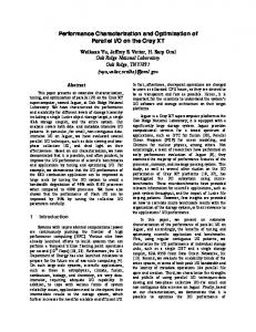
The PPT is powered by an all-solid-state modulator which combines IGBT commutation with advanced nonlinear magnetic switching technology. A discharge pulse repetition frequency (PRF) of 5000 pps can be achieved. The present per pulse energy is variable over a range of 2-7 J per pulse. A train of 6 pulses at 3600 pps is shown in the voltage waveform in Fig. (2). The thruster is pulsed through a primary capacitor bank with a total capacitance of 93.9 µF. The train pulsing is backed by a secondary capacitor bank with a capacitance of about 1 F. The waveform of each current pulse is very close to being critically damped and reaches a peak current pf 12.5 kA with a pulse width of about 3 µs as shown in Fig. (3). The critically damped nature of the current waveform is
Figure 1: Schematic of the SRL4-GFPPT.
350 300 250
Voltage (V)
2
200 150 100 50 0 -50 0.0
0.5
1.0
1.5
2.0
Time (ms) Figure 2: Waveform showing a train of 6 pulses at 3600 pps. The waveform is the voltage across the thruster electrodes which reaches a peak of 330 V before breakdown.
4
ZIEMER, CUBBIN, CHOUEIRI & BIRX: HIGH-EFFICIENCY PPT PERFORMANCE
τm
14
τb
12 mass pulse
Current (kA)
10
τp
8
burst 1
6
discharge pulses
burst 2
4
Figure 4: Burst operation mode used to maximize mass utilization efficiency. τp is the discharge pulse period, τb is the burst period and τm is the duration of the mass pulse.
2 0 -2 0
5
10
15
Time (µs)
20
25
thruster whose length is 10 cm. A cold flow of argon (400 m/s) takes about 250 µs to fill the chamber. At this value of τp the pulse repetition frequency is Figure 3: Current waveform of a single 3 µs discharge 4000 pps. If a valve with a 10 ms response time is pulse reaching a peak of 12.5 kA. The waveform is used, a burst of 40 pulses would be required to insure very close to being critically damped. maximum mass utilization efficiency. These bursts of pulses are then repeated at a frequency 1/τb dictated by the available power and the mission requirements. a direct result of the low inductance drive. In this For a burst repetition rate (BRP) of 1 Hz, and an enPPT the equivalent resistance, (Req = Rp + 2 · dL/dt) ergy per pulse of 5 J, the steady-state power required which is dominated by the time varying inductance from the spacecraft bus to operate the thruster is caused by the plasma sheet motion,pis greater than about 200 W. the imaginary impedance (Im(Z) = L/C). Energy is coupled very efficiently from the electrical power source to the plasma but as we will discuss further, 2.3 Efficiency Considerations this does not in itself result in an efficient thruster. After a series of experiments with three earlier proEnergy can be coupled into plasma internal energy or totypes (SRL1, SRL2 and SRL3-GFPPT), it was remotion in unusable directions as well as being coupled alized that the plasma sheet quickly collapsed into a into forward directed plasma acceleration. small angle cone centered on the tip of the central electrode. This should be expected to cause severe 2.2 High Mass Utilization Efficiency profile losses and to adversely effect the total efficiency. Since the acceleration is normal to the surface The low mass utilization efficiency problem that of the plasma sheet, a sheet geometry other than a plagued previous GF-PPTs is solved by adopting a planar annulus results in wasteful radial acceleration pulsing scheme that does not require high speed pro- of the propellant. The resulting inefficiency is termed pellant injection control. The thruster is operated in Geometric Profile Inefficiency . In addition the radial burst mode as shown in Fig. (4). In that figure, τp dependence of the axial velocity profile results in a is the discharge pulse period and is chosen such to Velocity Profile Inefficiency. Indeed, it was verified be the time it takes for the cold propellant to fill the from inspection of the electrodes of these early prothruster chamber right after the previous gas pulse totypes that the current sheet was sweeping the enhas been swept by a current sheet. τm , the duration tire length of the central electrode while barely movof the mass pulse, and τb , the period between burst ing along the external one. Such a non-ideal plasma of pulses, are chosen subject to available bus power sheet evolution also results in a diminished change and thrust level requirements. This relieves the re- in the total inductance which translates into limited quirements of fast response time for the gas valve and coupling of the electrical energy to the plasma dyallows for a mass utilization efficiency close to 100%. namics. As an illustrative example, consider the case of a In order to avoid these sources of inefficiencies, the
ZIEMER, CUBBIN, CHOUEIRI & BIRX: HIGH-EFFICIENCY PPT PERFORMANCE
sweeping plasma sheet must be maintained flat and normal with respect to the thruster axis. This was effected in the SRL4-GFPPT by increasing the radial aspect ratio (r/l) of the thruster and using radial mass injection from the base of the central electrode. These effects can be better understood through the following discussion. Upon the initial phase of plasma acceleration the sheet forms on the power input side of the propellant gas column and is driven through the cold gas. The plasma sheet entrains the cold gas as it moves forward in a process sometimes called the Snowplow effect. During the Snowplow phase, the magnetic pressure is balanced by two other pressures and the equilibrium condition can be written as: ∇Pnet = 0 = ∇(
B2 − N kT ) − ρ∇ · vv 2µ0
While the plasma acceleration is in the Snowplow phase, energy delivered to the cold gas per unit volume is given as ρv·v, however only half of this energy is available as kinetic energy (KE=1/2 · ρv · v); the remainder is deposited thermally and is rapidly converted into radiation. Any attempts to convert thermal energy into forward directed kinetic energy using such nozzles at these elevated temperatures and low densities is rapidly frustrated by the radiative cooling of the plasma and the excessively slow rates of internal modes recovery. This was further confirmed by our failure to detect an increase in the measured impulse when such nozzles were added. Once the plasma sheet has entrained all of the propellant mass, the equilibrium condition can be described as: ∇Pnet = 0 = ∇(
B2 − N kT ) − ρ · dv/dt 2µ0
In this case the efficiency of converting electrical energy to thrust is only limited by the ratio (2·dL/dt)/R and the profile inefficiencies. For this reason attempts are made to confine the initial propellant mass to a thin annular sheet located close to the base of the electrodes. Since the plasma sheet is driven by the magnetic pressure, P = B 2/2µ0 = µ0I 2 /8π 2 R2 (MKS), the radial gas injection provides a 1/R gas density profile which partially counterbalances the (1/R)2 magnetic pressure profile. This effect along with increasing the aspect ratio (r/l) proved very helpful in attaining high thrust efficiencies. As a result of these design iterations the SRL4GFPPT was designed with a 7.25 cm exit diameter
5
and a length of 6.26 cm. The total change in inductance due to the plasma sheet sweeping that length is about 12 nH compared to a source inductance of 3-4 nH.
2.4
Propellant Delivery Problem
With the issue of propellant utilization satisfactorily addressed there remains the important issue of propellant delivery which, is critical to the flight application of GF-PPTs. Gas valves are typically not reliable enough to deliver propellant directly from a central storage location to the individual thrusters. The statement that Gas valves eventually leak will draw little controversy. The solution adopted for this system requires the use of a separate plenum as a short term gas storage facility during maneuvering. The plenum would be filled with a quantity of propellant deemed appropriate for a given series of maneuvers. Gas propellant would be delivered to the thruster from the plenum using a high cycle-life valve which may be allowed to exhibit a fairly high leak rate when closed. A high quality, low leak rate valve would be used to deliver the desired quantity of propellant to the plenum. This primary valve between the main propellant storage tank and the plenum would only operate for a minimum of cycles (thousands of times less than the valves between the plenum and the individual maneuvering thrusters) and would, of course, be protected by redundant loops. During cruising the plenum tank would remain empty. Our present test setup is configured this way and the plenum is typically filled to a pressure of around 50 torr. The tubing from the central storage to the thruster is enough volume to act as the plenum. An alternative solution to the valving issue is the use of liquid valves in combination with a propellant which would later be vaporized when it impacted the inner surface of the PPT center conductor. Liquid valves are not prone to leakage because surface tension will prevent most liquids from flowing through any hole smaller than a few microns. Presently it is envisioned that this valve might use technology similar to that employed by Hewlett Packard in inkjet printer heads. Here the liquid is confined to remain in a small diameter capillary (1- 2 microns in diameter) by its own surface tension. The application of an electric field provides enough additional incentive for the liquid to flow through the capillary. Alcohol exhibits a good mix of vapor pressure, high dielectric constant and surface tension for this application.
6
3
ZIEMER, CUBBIN, CHOUEIRI & BIRX: HIGH-EFFICIENCY PPT PERFORMANCE
Impulse Measurement Technique
The impulse produced by a pulsed plasma thruster is measured by monitoring the position of the thruster mounted at the end of a swinging gate type thrust stand. The thrust stand has a vertical rotational axis through two flexural pivots that allows relatively free rotational motion in the horizontal direction. Knowing the position of the thruster at all times allows the thrust force to be determined based on calibrated thrust stand dynamics. In the case of very short duration accelerations, as with most PPTs, the force can be considered impulsive and observing the change in velocity of the effective thruster mass is enough to determine the impulse magnitude. Although details of this technique have been described by the authors and others previously[4], we give below a short review of the pertinent issues. Briefly, the facilities, thrust stand dynamics, two position measurement techniques, and the effective mass calibration procedure will be presented in this section.
3.1
Test Facility
Figure 6: Schematic of swinging gate thrust stand. extent, vibrationally isolated from the vacuum tank by rubber pads. More details on the thrust stand are given in refs. [4] and [5]. The dynamics of this slightly damped spring-mass system are well understood. Since the thruster is mounted well away from the rotational axis, its motion can be described accurately as a linear displacement over a small angle. In response to an impulsive force, Ibit , the position of the thruster, x(t), initially at rest is given by, ³ p ´ Ibit /meff x(t) = e−ζωn t p sin ωn t 1 − ζ 2 , (1) ωn 1 − ζ 2
The vacuum vessel used for this study is a 2 m diameter, 5 m long fiberglass tank with eight optical access ports shown in Fig. (5). A vacuum level of 5 × 10⁻⁵ torr, was maintained by a set of two 1.3 m diffusion pumps. Each pump has a pumping capacity of 95 m3 /s and is backed by a roots blower (1340 cfm) and a mechanical pump (150 cfm). A nylon mesh net covers the intakes to the diffusion pumps. During the experiments reported here, the mass flow rates were below 7 mg/s and the effects of pulsed mass injection on the background pressure during the experiments were barely detectable. where ζ is the damping coefficient, ωn is the natural frequency, and mef f is the effective mass of the system. The natural frequency and damping coef3.2 Thrust Stand Dynamics ficient can be determined from the position history The thruster assembly, weighing 7.2 kg, was can- regardless of the impulse value. If the arm is movtilevered on a vertical axis, swinging gate, thrust ing before the impulse occurs, then the post-impulse stand shown schematically in Fig. (6). The mass sine wave could be offset by a phase angle. In this is supported by two flexural pivots mounted on case, a change in the velocity must be considered, the hinge line, permitting horizontal rotation of the Ibit = mef f ∆x. ˙ The velocity is the derivative of posithruster and support arm. These external cables and tion with the added phase offset, propellant lines act along with gravity to provide a p Ibit restoring force and a small amount of damping to the x(t) ˙ = e−ζωn t [cos(ωn t 1 − ζ 2 + φ)− mef f almost exclusively horizontal motion of thruster. The p ζ resulting restoring torque gives the system a natural p sin(ωn t 1 − ζ 2 + φ)]. (2) frequency of .25 Hz. The thrust stand is, to a large 1 − ζ2
ZIEMER, CUBBIN, CHOUEIRI & BIRX: HIGH-EFFICIENCY PPT PERFORMANCE
7
Figure 5: Thrust stand installation in fiberglass vacuum tank at Princeton’s EPPDyL. Using the coefficients found from the position curve (including the phase offset) and the calibrated value of the effective mass, the velocity change can be found without actually taking the derivative of the measured position signal. In Fact, numerically differentiating a digitally stored position trace would lead to large errors without extensive filtering that could adversely affect the results. For the impulse measurements described in this paper, a damped sinusoid is fit to the position history before and after the impulse to determine all the required coefficients. The effective mass is determined by a calibration procedure. Techniques for measuring the position and calibrating the effective mass of the system are presented in the next sections.
3.3
Position Measurement Systems
Two devices for measuring the position of the thruster have been used in this paper. The interferometric proximeter system (IPS) is used for the accurate resolution of small impulses including cold gas pulses. A radio frequency position transducer is also used to measure the position of the thrust arm. Both systems can be used to measure any magnitude of impulse considered in this paper. 3.3.1
Interferometric Proximeter System
The interferometric proximeter system (IPS) has been described in detail in ref. [4]. The IPS mea-
Vacuum Tank Flexural Pivots Corner Cube (1 of 2) Window Right Angle Prism Beam Splitter Adjustable Mirror Cylindrical Lens HeNe Laser IPS Table Top
Thruster
Beam Splitter HeNe Filter (1 of 2) Diode Sensor (1 of 2)
Figure 7: Thrust stand set-up with the Interferometric Proximeter System (IPS).
sures position by monitoring the intensity of an interference pattern produced by a Michelson type interferometer. In our application, the corner cubes which form the two legs of the interferometer are both mounted on the arm of the thrust stand near the thruster mount. In this case, the position measured is the relative displacement between the two corner cubes. This configuration is necessary to reduce the sampling frequency required for long duration (> 10 second) position measurement[4]. More sensitive ar-
8
ZIEMER, CUBBIN, CHOUEIRI & BIRX: HIGH-EFFICIENCY PPT PERFORMANCE
0.6
Position (µm)
0.4 0.2 0.0 -0.2 -0.4 -0.6 0.00
0.05
0.10 Time (s)
0.15
0.20
Figure 8: Background vibrational noise on relative thruster displacement as measured by the IPS.
system along the thrust axis allows the effective mass to be determined from the dynamic equations above, eq. 1 and 2. The known impulse is supplied by a force transducer mounted at the end of a swinging pendulum arm triggered from outside the vacuum tank. The force transducer has been calibrated and a shows a 87.6±0.6 N/V linear voltage response between 0.5 and 100 N and can be set to deliver a wide range of impulses by adjusting the pendulum release angle and striking material. The force from the transducer is recorded and numerically integrated at the same time as the displacements from both the IPS and proximeter are measured. This technique yields all necessary data to determine meff for both position measurement systems simultaneously within ±2%.
4 rangements can be made but are not required for these measurements. This relative displacement is typically one tenth the absolute displacement of the thruster, and the IPS has a position resolution well within the required regime for any impulse measurement presented here. Using the IPS for position measurement is required for high accuracy, low impulse applications such as a cold gas pulses as described in section 4.3. A sample of background vibration position output from the IPS is shown in figure 8. 3.3.2
Radio Frequency Proximeter
A Bently Nevada position transducer has been used for many years to measure the impulse from high power gas-fed pulsed plasma thrusters[5]. The proximeter measures the absolute linear displacement of a steel target mounted directly below the thruster. The proximeter is useful for positioning the arm in a stable configuration and for it’s relative simplicity in operation. Although the proximeter is not as accurate as the IPS, it was able to perform all of the impulse measurements presented in this paper. When checked against the IPS with appropriate background noise filtering and using a scaling factor, both position measurement systems agreed to within less than a percent of the peak displacement found in a typical impulse from the SRL4-GFPPT.
3.4
Thrust Stand Calibration
Performance Measurements
For the SRL4-GFPPT, performance is calculated based on the impulse produced by a measured amount of stored energy and the amount mass that was accelerated. The efficiency of this device is described by the ratio of energy in the exhaust beam to the energy stored in the capacitor, η=
1 2 2 mbit ue 1 2 2 CV0
=
2 Ibit , mbit CV02
(3)
where the impulse bit is equal to the product of the mass bit and the exhaust velocity, Ibit = mbit ue , the initial voltage is V0 , and the capacitance is C. Specific impulse, Isp , can also be determined from the impulse bit and mass bit, Isp =
Ibit . mbit g
(4)
To evaluate both of these parameters, three measurements are required for each individual pulse: stored energy, mass bit, and impulse bit. For all data presented in this paper, a train of six pulses was fired per trial at close to 274 µs intervals as shown in figure 2. All results consist of what would be the average value of a single pulse in that train. The techniques for finding these average per-pulse values are described below.
4.1
Pulse Energy Determination
The last remaining parameter for determining the im- The primary capacitor voltage was measured at the pulse bit from the position history of the thruster is charging supply through a calibrated 1000:1 voltage the effective mass. Supplying known impulses to the probe. For each set of pulses, a voltage trace was
ZIEMER, CUBBIN, CHOUEIRI & BIRX: HIGH-EFFICIENCY PPT PERFORMANCE
Figure 9: Schematic of power and propellant connections to the SRL4-GFPPT. captured on a digital oscilloscope showing the charging cycle of the capacitor for all the pulses in the set. The voltage trace was squared and multiplied by the measured capacitance, 93.9±0.2 µF, resulting in a plot of energy during the pulse train accurate to within 1.5 %. The peak energy before every pulsed was averaged to determine the energy per pulse and the standard deviation of that average is used as the error in this measurement. For most measurements, this error is below 4%.
4.2
Mass Bit Calculation
Propellant, in this case argon, is supplied to the SRL4-GFPPT through a valve, choking orifice, and plenum arrangement as shown in figure 9. The valve is located approximately 10 cm upstream from the thruster propellant injection ports. It is opened and closed by the control module and timed by a signal generator. For these experiments, the valve was open for 45 ms and the thruster was set to fire 40 ms after the valve opened to allow sufficient time for the gas to reach a steady flow rate. This time could be reduced with faster acting valves. The mass flow rate is controlled by changing the pressure in the plenum upstream of the sonic orifice. Soon after the valve is open, the flow is choked and a steady-mass flow rate is reached. In this case, the sonic orifice is a copper plate with a 0.36 mm hole. Using a pressure transducer located just downstream of the sonic orifice, the mass flow rate was seen to reach a steady state condition within 20 ms of the valve opening at relatively high mass flow rates. Integrating this trace gave an
9
effective valve time of 65 ms for the calculation of cold gas exhaust velocity. The mass flow rate as a function of plenum pressure has been calibrated by measuring the volume of the plenum and propellant lines, filling them up to approximately a pressure of 400 Torr with argon, and gradually venting them into a vacuum. The mass flow rate out of the plenum, through the sonic orifice, and into the vacuum is proportional to the plenum pressure. The plenum and propellant lines were evacuated gradually by opening the valve for twenty seconds at a time. After a short equilibration period, a pressure measurement was taken and the valve was opened again. For this sonic orifice, the mass flow rate for typical operating plenum pressures (between 35 and 350 Torr) is given by m ˙ = 28.7 × Ptorr − 265) × 10−9 , where the pressure is in Torr and the mass flow rate is in kilograms per second. This value is accurate within one percent from the correlation coefficients to a linear fit of measured pressure vs. calculated mass flow rate. The mass bit itself comes from the timing of the pulses within a set. This timing is apparent from the main capacitor voltage trace, figure 2. Except for the first two pulses which are slightly longer, all the later pulses are close to 274 µs between discharges. This time multiplied by the mass flow rate generates an average mass bit for each pulse in the pulse train. Obviously, for the first pulse, mass is entering the thrust chamber for much longer than 274 µs, however, the cold gas exhaust velocity has been measured at close to 400 m/s. At that speed, if the gas is moving primarily in the axial direction, it would begin to leave the thrust chamber after only about 200 µs. Therefore, we expect similar gas loading conditions for each pulse.
4.3
Impulse Measurement
The general technique for impulse measurement has been described in section 3. This section is meant to describe more of the details of the measurements. First, the raw proximeter position trace is captured by an oscilloscope and downloaded to a computer for storage. In general, IPS data is also taken simultaneously for comparison of proximeter data. Second, both of the traces are smoothed with a low-pass box filter that simply averages a point based on a chosen number of near-by points. As shown in figure 8, the background noise is at a much higher frequency (∼8 Hz) than the natural frequency of the thrust arm (∼0.25 Hz) allowing the filtered data to be an ex-
10
ZIEMER, CUBBIN, CHOUEIRI & BIRX: HIGH-EFFICIENCY PPT PERFORMANCE
a change in the average impulse bit larger than the already assumed standard deviation per shot. Therefore, assuming the impulse bit deviation is the largest source of error, and that the mass bit is correct within 2%, the efficiency will have an error within 9.2% of its value and the specific impulse will be within 8.3% of its value.
20 15
Position (µm)
10 5 0 -5 -10
4.5
Final Results
Raw Position Filtered Position
-15 -20
100
-10
-5
0
5
10
2.0
E=5J
15
Time (s)
40 80 1.5
Ib 60
I b (µNs)
Efficiency (%)
30
m b (µg/shot)
Figure 10: Plot of raw position history and filtered position history for a a six pulse train of 5 J, 0.2 µg, 33 µN-s pulses.
tremely good representation of the position. A plot 1.0 showing a sample raw and filtered proximeter signal m η 20 b is shown in figure 10. 40 For each data point at a different mass bit, ten trials of “cold” gas flow were taken without charging the capacitors yielding a cold gas impulse bit. These 0.5 ten trials were averaged and compared to an exten10 20 sive database of previous experiments with the same thruster to insure repeatablity. Each individual impulse measurement has an error not greater than 3%. The standard deviation from trial to trial of cold gas 0 0 0.0 impulses is also close to that value. 3 0 5 10 15 20x10 For these data points, one trial was used for the Isp (s) “hot” impulse bit calculation. Again, from previous experiments with many hot pulses, the impulse bit magnitude has shown a shot to shot variation of Figure 11: Measured performance data for the SRL4about 8% near the impulse bit values presented in GFPPT at a discharge energy of 5 Joules. this paper. This is the value that will be used for the error on each impulse bit measurement. The performance of the SRL4-GFPPT with argon propellant is presented in figures 11, 12 and 13 and outlined in tables 1 and 2. There are obvious trends 4.4 Error Analysis in the data that should be noted. First, for the fixed Individual error sources have already been discussed energy data, the impulse bit is also almost constant. in the previous sections. The largest source of error is Even at higher and lower energies, the impulse bit the assumed standard deviation in the impulse mea- seems to scale linearly with the energy. Therefore, surement. Another possibility for large errors occurs this thruster seems to possess a fixed E/Ibit over a from the choice of a time scale for the mass bit al- variety of conditions. This is also evident from the though that has not been quantified. Attempts were linear relationship between specific impulse and effimade to fire the thruster at the same energy and ciency. The highest efficiency was 50% at 5 J with an mass bit settings with a different number pulses in impulse bit of 32 µNs and a mass bit of .2 µg/shot. the train to subtract out the cold gas and first pulse The highest efficiency point still falls on the same contributions. This technique, however, did not show line as the rest of the data, indicating that it is a rea-
ZIEMER, CUBBIN, CHOUEIRI & BIRX: HIGH-EFFICIENCY PPT PERFORMANCE
0.30
50
0.5 µg/shot
0.5 µg/shot Impulse Bit (µN-s)
0.25
Efficiency (%)
11
0.20 0.15 0.10 0.05
40 30 20 10 0
0.00 0
1
2
3
4
5
6
7
8
Energy per Pulse (J)
Figure 12: Measured efficiency of the SRL4-GFPPT versus energy at a fixed mass bit (.5 µg/shot) .
0
1
2
3
4
5
6
7
8
Energy per Pulse (J)
Figure 13: Measured impulse bit of the SRL4GFPPT versus energy at a fixed mass bit (.5 µg/shot) .
sonable data point. In addition, a trial with similar theoretical effort to complement these explorations is conditions shows that it is quite repeatable. It is also relevant to note that based on a .8 µg/C ongoing. erosion rate measured at JPL, the fractional contribution of eroded mass to the total mass bit used by References the thruster ranges between 1 and 10%. This effect is within the error bars of the measured data. [1] E.Y. Choueiri. Optimization of ablative pulsed plasma thrusters for stationkeeping missions. Journal of Spacecraft and Rockets, 33(1):96–100, 5 Summary and Comments 1996. The performance of a repetitively pulsed gas-fed pulsed plasma thruster was characterized using a high-accuracy interferometric microthrust stand. While the efficiencies of two earlier prototypes did not exceed 3% at 5 J, substantial improvements to the performance were effected on subsequent iterations. Using advanced nonlinear magnetic switching technology, a low inductance of 3-4 nH was achieved, warranting efficient coupling of the discharge energy to the plasma. This feature, along with judicious changes to the geometry and dimensions of the electrodes and the radial gas injection (which assured low profile losses) resulted in achieving a total efficiency of 50% at 5 J with argon (at an impulse bit of 32 µNs and a mass bit of .2 µg/shot). A mass utilization scheme based on burst mode operation allows attaining mass utilization efficiencies near 100%. Now that high thrust efficiencies have been attained at these low energy levels, we expect that the specific impulse can be brought down by using a heavier gas like xenon and exploring parametric dependencies such as increasing the system capacitance and lowering the total resistance. A parallel
[2] S. Domitz, H.G. Koshmal, P. Ramins, and J. Stevens. Survey of electromagnetic accelerators for space propulsion. Technical Report NASA TN D-3332, NASA, NASA-LeRC, 1966. [3] P. Gloersen. Current status of pulsed plasma engine development. In 2nd Propulsion Joint Specialist Conference, Colorado Springs, CO, USA, 1966. AIAA-66-566. [4] E.A. Cubbin, J. Ziemer, E.Y. Choueiri, and R.G. Jahn. Laser interferometric measurements of impulsive thrust. Review of Scientific Instruments, 68(6):2339–2346, 1997. [5] R.L. Burton, K.E. Clark, and R.G. Jahn. Measured performance of a multi-megawatt MPD thruster. Journal of Spacecraft and Rockets, 20(3):299–304, 1983.
12
ZIEMER, CUBBIN, CHOUEIRI & BIRX: HIGH-EFFICIENCY PPT PERFORMANCE
mbit (µg) 0.2 0.2 0.3 0.4 0.5 0.6 0.7 0.8 1.0 1.5 2.0 ±2%
Ibit (µN-s) 32.6 31.1 28.8 28.9 29.3 30.1 29.2 28.4 29.5 29.8 29.7 ±8%
Isp (s) 16600 15900 9800 7380 5970 5120 4250 3630 3010 2030 1770 ±8.3%
η (%) 49.9 45.5 25.9 20.0 16.1 14.2 11.5 9.6 8.4 5.6 4.2 ±9.2%
Table 1: SRL4-GFPPT Performance Data for a fixed energy of 5.3±0.2 J. The last row in the table is the error from each measurement.
Energy (J) 2.95 5.33 6.83 ±4%
Ibit (µN-s) 14.5 29.3 41.2 ±8%
Isp (s) 2960 5970 8410 ±8.3%
η (%) 7.1 16.1 24.9 ±9.2%
Table 2: SRL4-GFPPT Performance Data for a fixed mass bit of 0.5 µg. The last row in the table is the error from each measurement.