boron surface phase. The tunneling transport and the influence of the boron surface phase on the transistor behavior is investigated. The transistor performance ...
Jpn. J. Appl. Phys. Vol. 40 (2001) pp. 3131–3136 Part 1, No. 5A, May 2001 c �2001 The Japan Society of Applied Physics
Performance Improvement in Vertical Surface Tunneling Transistors by a Boron Surface Phase Walter H ANSCH, Peter B ORTHEN, Jörg S CHULZE1 , Christoph F INK1 , Torsten S ULIMA1 and Ignaz E ISELE1 Institute for Technical Electronics, Technical University Munich, 80333 Munich, Germany, 1 Institute of Physics, University of the German Federal Armed Forces, Munich, Germany (Received September 4, 2000; accepted for publication February 5, 2001)
t d te gh i ec yr ot p pr co by
The fabrication and characteristics of silicon tunneling transistors based on vertical metal-oxide-semiconductor (MOS) gated pin-diodes are shown. In these devices the tunnel junction is formed between an influenced MOS-channel and an abrupt, ultra-highly doped boron layer. The ultra-high doping amount of about 2.6 × 1014 cm−2 is achieved by the formation of a √ √ 3 × 3-R30◦ boron surface phase. The tunneling transport and the influence of the boron surface phase on the transistor behavior is investigated. The transistor performance is characterized by a current gain between 3 and 5 orders of magnitude at a low supply voltage of −0.2 V with saturation behavior. KEYWORDS: silicon, vertical MOS-gated surface tunneling transistor, pin-diode, delta-doping, boron surface phase
1. Introduction
Tunneling devices are thought to be possible candidates for post silicon metal-oxide-semiconductor field effect transistors (MOSFET). One benefit of these devices is the increase of carrier speed due to quantum-mechanical tunneling combined with a higher functionality (e.g. possible multi level logic). Recent year publications show a rich spectrum of possible tunneling devices proposed or fabricated in several materials and heterostructures.1) Although few of these devices are quite successful according to some (but not all) benchmarks, none has found for large-scale commercial application in digital and analog electronics to date. A novel device should be based on silicon to match well with existing conventional logic circuitry. Based on our vertical MOSFET technology2, 3) we modified the fabrication process to create a vertical MOS-gate controlled surface-tunneling transistor (VSTT)4) in silicon. In such a device the tunneling process takes place between an influenced vertical MOS-electron channel and a degenerated p-doped drain. 2. Device Fabrication
2.1 Device structure A planar pendant of this device was first by Quinn et al.5) and realized by Baba et al.6) and Koga and Toriumi.7) Both were focused on the demonstration of a gate-controlled Esaki-tunneling effect in forward direction to receive a switchable negative differential resistance (NDR). A small NDR was only demonstrated by Koga and Toriumi using special wafers, fabricated by the so-called technique of separation by implanted oxygen (SIMOX), and special gate constructions. This is understandable, because compared to compound semiconductors and germanium in silicon several problems exist for the realization of Esaki-tunneling. Silicon exhibits an indirect band gap, therefore interaction with phonons or point defects is necessary to conserve energy and momentum in the band-band tunneling process, which in consequence lowers the tunneling rates significantly compared to direct tunneling materials. Also degeneration due to heavy doping which moves the Fermi level into the bands needs about one order higher doping in silicon than in germanium.
The favorable high doping levels around 1020 cm−3 exceed the defect-free solubility limit of doping atoms when using common MOS-processes and also the abruptness of the junction may be destroyed by out-diffusion due to high temperature processes. In our established vertical MOSFET technology these problems were solved to a degree that for MOSFETs with 60 nm channel length a yield of about 70% was achieved and threshold voltage fluctuations on the dies were reduced to a standard deviation of about σ = 3%.8) These values meet the requirements for future 50 nm MOSFETs as proposed by the Semiconductor Industry Association (SIA) roadmap.9) Using this technology, only exchanging the type of drain doping, the VSTTs presented here were fabricated. As substrates 3�� -silicon wafers, n+ -doped (ρ ≤ 0.015 �·cm) were used, whereas the doping is not sufficient to shift the Fermi level into the conduction band but acts as the source electrode. The substrates were cleaned wet-chemically leaving the surface covered with a thin protective oxide. Then the wafers were transferred into a multi-chamber ultra-high vacuum (UHV) system. After a thermal desorption step at 900◦ C for removing the native oxide the layer system was deposited at 700◦ C by means of molecular beam epitaxy (MBE). Directly on the n+ -substrate a 100 nm thick intrinsic silicon layer was grown acting as the body region for the MOS-channel. To realize the necessary abrupt, degenerately doped p+ -region first a so-called delta layer was deposited. In this delta layer within a thickness of about 3 nm the boron amounts about 3 × 1019 cm−3 . The drain contact region was deposited on top with a thickness of 200 nm and a boron doping of 2 × 1019 cm−3 . The wafers were unloaded from the UHV-system and were mesa-etched for device patterning and isolation. On the vertical side walls a gate oxide with a thickness of 20 nm was grown (800◦ C, 30 min) and covered with n+ poly-silicon. The gates were patterned and isolated with a low-pressure chemical vapor deposited (LPCVD) nitride. Finally the contact holes were opened in the nitride and Al was used for the top p+ -contact and a double layer of Ti/W and Pt was used to form the n+ -source contact. It should be mentioned that all processes are optimized not to exceed the temperature of 800◦ C. A schematic sketch of the VSTT is depicted in Fig. 1.
3131
3132
Jpn. J. Appl. Phys. Vol. 40 (2001) Pt. 1, No. 5A
W. H ANSCH et al.
Drain p+n+-tunneling junction
p+ i-Si
Source metal
100nm
MOS-channel
p++ delta layer
GOX Poly-Si nitride
metal
[110] [110]
Gate metal
t d te gh i ec yr ot p pr co by
n+ substrate
common source
Fig. 1. Schematic sketch of the VSTT.
For a first series of VSTTs (100)-wafers were used for the following reasons: the high delta doping of about 2 × 1019 cm−3 (which corresponds to an integral area doping of about 1 × 1013 cm−2 ) is on the limit of boron solubility in silicon at 700◦ C and can be realized by a so-called solid phase epitaxy (SPE) process. In this process the boron is deposited at room temperature on the silicon surface and covered with 3 nm amorphous silicon. When the temperature is raised to about 700◦ C this delta layer recrystallizes. On Si(100) this happens without any defects whereas on Si(111) this process may result in the formation of dislocation lines which would be killer defects for the vertical device. In addition the silicon (100)-orientation will result in four identical vertical {110} side walls for the transistor mesa after etching.
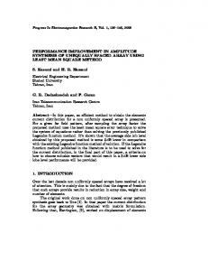
2.2 The Boron Surface Phase In former works10, 11) it was shown that boron can form a so-called boron surface phase (BSP) on silicon (111). Due to the atomic arrangement and in order to minimize the surface energy deposited boron atoms saturate the dangling bonds of three silicon surface atoms. In this top position (named T4 ) the boron does not act as a doping atom and is electrically inactive. The amount of this periodic √ sites√is about 2.6 × 1014 cm−2 and a new surface unit cell 3 × 3-R30◦ (compared to silicon) is created (Fig. 2). It was shown by Stimpel et al.12) that a phase transition from such an electrically inactive BSPeia into an electrically active BSPea can be performed. Induced by rapid thermal annealing (RTA) for 10 s at 825◦ C the boron jumps from its T4 -positions [Fig. 3(a)] in S5 -positions directly underneath the silicon surface [Fig. 3(b)]. In this bulk-position the boron is bonded to four silicon atoms and therefore acts as an electrically active doping atom. Further high temperature treatment (T > 825◦ C) will cause out-diffusion of boron into the silicon bulk [Fig. 3(c)]. Since after the activation step [Fig. 3(b)] the boron is already covered by silicon atoms and strongly bonded, no additional coverage with silicon at room temperature and no recrystallization step is necessary as in the case of Si(100). The epitaxial overgrowth can take place at 700◦ C without forming any dislocations. The existence of such a BSP offers the possibility to increase the boron doping amount far above the solubility limit
Fig. 2. Top view of an unit-cell of a BSPeia (light gray circles) in T4 -positions above the silicon (111) surface (dark gray circles).
[111]
[111]
[111]
(a)
(b)
(c)
Fig. 3. Diffusion of boron atoms (white circles) from a BSPeia (a) via the formation of a BSPea (b) at 825◦ C annealing temperature into the silicon bulk (c).
as it is given for this temperature by a conventional diffusion, deposition or implantation process. For this reason the silicon substrate orientation was changed to (111) in a second series of VSTTs to allow the introduction of the BSP. The advantage of ultra-high p-doping is compromised by the creation of non identical mesa side walls after etching. Due to the 3-fold symmetry of a silicon (111) surface two {110} and two {112} facets are formed if a rectangular mask opening is used and aligned parallel to the wafer flat. 3. Device Operation To understand the basic device behavior we used the theoretical equations13) for pn-current, tunneling current and ex-
Jpn. J. Appl. Phys. Vol. 40 (2001) Pt. 1, No. 5A -3
2x10
-3
1x10
-3
0 -2
-3
-3
Itun Ipin Iexc SUM
additional gate voltage
-2x10
Vgate: 6V
0 -1x10
3133
2 Current Contributions in Esaki Diodes
Drain current [A]
Drain current [A]
3x10
W. H ANSCH et al.
-4
room temperature
-6
-3x10
Vg [0 - 15V] in steps of 1.5V
12 V
-8 -1
-3
A=200 m, w= 50 m, gate oxide: 20nm
9V
15 V reverse
-1
-0.5 -0.4 -0.3 -0.2 -0.1 0.0 0.1 0.2 0.3 0.4 0.5
-2.0
-1.5
-1.0
forward
-0.5
0.0
0.5
t d te gh i ec yr ot p pr co by Drain voltage [V]
cess current. The empirical parameters in these equations were adjusted to show the basic behavior of the three current components in Fig. 4 and are not adjusted to fit the experimental values. Without gate voltage the vertical structure acts as a pin diode where the p+ -and n+ -region are separated by 100 nm intrinsic silicon. This current–voltage (I –V ) characteristics is indicated in Fig. 4 by open squares. An ideal Esaki tunneling current is shown by the open circles whereas in realistic devices an additional excess current appears (triangles) which is due to defects. By applying a positive gate voltage on the vertical pin-structure an electron channel is influenced beneath the gate oxide as in a conventional MOSFET. The contact region between the created n+ -channel and the p+ -drain now forms a band-band tunneling barrier like in an Esaki diode. The amount of electrons supported by the channel and the tunneling region can be controlled by the MOS gate field. Due to the above mentioned problems for Esaki-tunneling in silicon the change in I –V characteristics is expected to be small in forward direction, but significant transistor action is enabled in reverse direction. 4. Electrical Results
Examples of the experimental I –V characteristics for a VSTT of the first series are shown in Figs. 5 and 6. The output characteristics in Fig. 5 exhibits the predicted change from pin-diode behavior to a tunneling diode due to the applied gate voltage. The maximum gate voltage is limited to 15 V to avoid gate break-through. The transfer characteristics is shown in Fig. 6. Even for low values of supply voltage VSD = −0.2 V the gate controlled current gain amounts to three orders of magnitude. The value of the leakage current is about 4 × 10⁻¹⁰ A/µm gate width at a supply voltage of −1.0 V. Compared to a MOSFET with identical channel length the leakage current is about one order of magnitude lower as it is acceptable for future 100 nm MOSFETs.9) The reason is the high p+ /n+ -energy barrier. The threshold voltage of the device is defined by the crossing point of the tangential lines to the leakage current and the exponential current increase. As the fabricated devices show the threshold voltage can be adjusted by the thickness
Fig. 5. Experimental output characteristics of a VSTT on (100) substrates at room temperature.
-5
Drain current [A]
Fig. 4. Basic I –V characteristics of a pin-diode and an Esaki-tunneling diode as calculated by using theoretical equations.13)
1.0
Source-drain voltage [V]
10 -6 10 -7 10 -8 10 -9 10 -10 10 -11 10 -12 10 -13 10 -14 10
VSD= -1.0 V -0.8 V -0.6 V -0.4 V -0.2 V
A=200 m, w=50 m, gate oxide: 20nm
room temperature
Vt
Gate currents
-10mV
-2
0
2
4
6
8
10
12
14
16
Gate voltage [V]
Fig. 6. Experimental transfer characteristics of a VSTT on (100) substrates. The crossing of the two tangential lines is used to define the threshold voltage for this device. The associated gate currents are shown in addition.
of the oxide, but is also influenced by the thermal budget of the fabrication processes. For higher gate voltages the I –V characteristics saturates. The voltage gain d VD /d VG at constant ID is smaller than unity in the presented devices with a gate oxide thickness of 20 nm. Our simulations indicate that depending on the actual device layout, the voltage gain is above unity, when the gate oxide is in the range of 5 nm and thinner. In MOS logic circuits a voltage gain above unity is requested, although in single transistor applications, like 1-T memory cells, this requirement is not necessary. For a future tunneling logic the requirements on current and voltage gain must be investigated. Compared to the first series on Si(100) the following Fig. 7 shows the I –V characteristics of the VSTTs of the second series on silicon (111) with the incorporated BSPea . The gate-controlled current gain with the BSP is clearly increased to nearly five orders of magnitude (see for example at Vsd = −0.25 V) compared to the conventionally delta-doped device in Fig. 6. This indicates that due to the higher p+ -doping the depletion region with the BSP is thinner and allows higher tunneling rates.
3134
Jpn. J. Appl. Phys. Vol. 40 (2001) Pt. 1, No. 5A
W. H ANSCH et al.
Vgate 13.5 V 12 V 10.5 V 9V 7.5 V 6V 4.5 V 0V
BB Gener
Electrons
2
A=400 m, w= 80 m, gate oxide: 20nm room temperature
-2.0
-1.5
-1.0
-0.5
0.0
0.5
1.0
Signed Log
Log |x|
BB Ge ne r
15. 35
23 .2
13. 21
21
11. 07
18 .8
p+ drain
-2.5
oxide
n+ source
Drain current [A]
-4
10 -5 10 -6 10 -7 10 -8 10 -9 10 -10 10 -11 10 -12 10 -13 10 -14 10
8.93
16 .6
14. 4
6.79
14 .4
4.65
12 .2
2.51
10
29 .28 27 .6
20. 69 19. 63
25 .4
17. 49
0.3199
100 nm
Fig. 7. Experimental output characteristics at room temperature for a VSTT on (111) substrates with the BSP (integral boron surface concentration ∼ 2.6 × 1014 cm−2 ).
5. Discussion
5.1 The tunneling effect Besides the device operation explained in section 3 the question may arise if the presented I –V characteristics can be explained by a different physical mechanism in charge carrier transport, especially by a somehow gate-controlled avalanche break-through. We exclude a main contribution of this effect for several reasons. First, the gate current plotted in Fig. 6 is not effected by the applied voltages. In the case of impact ionization in the turned-on device (which means gate bias in the saturation region above 6 V) an increase in the substrate current and in the gate current must be induced. In our vertical devices the “substrate” region between source and drain is surrounded by the gate and not separately connected to an external voltage. Therefore created charge carriers must contribute to the source-drain current or the gate current. Also it should be assumed that an avalanche effect is symmetrical concerning the channel polarity. The potential drop and the strength of the electric field is symmetrically whether a n- or a p-channel is influenced. But by extending the gate bias from plus to minus to create a p-channel, an increase in current above the off-current level does not occur. But this effect can be easily explained in terms of tunneling transport. If the device is biased under reverse conditions (Figs. 5 and 6) with n+ -source at ground and p+ -drain at negative voltage and a positive gate voltage is applied then the electrons will tunnel from occupied states in the p+ -drain valence band in empty n-channel states causing an electron current between drain and source. In contrast by applying a negative gate voltage the influenced p-channel extends the p+ -drain region towards the n+ -source. But in this case no electrons can pass over from the p+ -drain into the p-channel and therefore no electron tunneling can take place from the p-channel into the n+ -source. In Fig. 8 a simulation of the tunneling transport is shown in a simplified device. The simulations are done with MEDICI using hydrodynamic energy transport, the impact generation and the band-band-tunneling option. The delta-doped layer at drain is not included in this simulation, instead the doping amount of n+ -source and p+ -drain is set to be 1 × 1020 cm−3 ,
29. 28 27. 6 25. 4 23. 2 21
18. 8 16. 6
12. 2 10 7.821
7.82 1
t d te gh i ec yr ot p pr co by Source-drain voltage [V]
Sign ed Log
Fig. 8. 2D-plot of electron density [electrons/cm3 ] (background) and tunnel probability [electrons/cm3 /s] (island inset) in the presented device structure. The device is biased in reverse direction according to Figs. 5 and 6 with source at ground, drain at −0.2 V and gate at +15 V.
separated by a 100 nm lightly p-doped (1×1017 cm−3 ) region. The gate oxide is chosen to a thickness of 20 nm as for the experimental device. Figure 8 shows the overlay of two pictures. Starting from n+ -source the regions of electron density are plotted. The electron channel beneath the oxide can be recognized also the increasing confinement of the electrons towards the p+ -drain barrier. Near the point of maximum confinement at p+ -drain the simulated tunnel probability is shown as an inset. The shape and the intensity of the tunnel region depends strongly on the chosen geometry and bias conditions as a series of simulations show. The band-band tunneling current calculated by MEDICI is about 4 × 10⁻⁸ A/µm gate width for the bias conditions given. This will result in a total current of 2 µA for the device with 50 µm gate width compared to the experimental value of 0.2 µA in Figs. 5 and 6. This shows that the order of magnitude for tunneling is already reasonable, taking into account the realistic doping profile in the experimental device. The dependence and optimization of the tunnel characteristics due to the geometrical structure will be discussed in detail in a following paper. The tunneling behavior is strongly supported by low temperature measurements at 77 K (Fig. 9) and 4.2 K. As it is known from examinations of silicon Esaki diodes additional structures in the I –V characteristics appear at low temperatures.14) In the case of silicon with an indirect energy gap these structures were identified to correspond with phonon energies which are necessary to allow phonon-assisted tunneling. Due to the good crystal quality, the intrinsic high p+ -n+ energy barrier and the 100 nm intrinsic region the leakage current of the device is below our measurement limit of 10−14 A for low gate and source-drain bias. This region under the measurement limit is more increased at a temperature of 4.2 K; here, even for the highest gate voltage no measurable current is detectable in the region of ±100 mV source-drain voltage around zero bias. But because this region exhibits the footprint of the phonons the second derivative d 2 I /d V 2 of the I –V characteristics at Vg = 12 V in Fig. 9 is presented in Fig. 10 for Vsd between ±100 mV. While in the first derivative the contribution of var-
Jpn. J. Appl. Phys. Vol. 40 (2001) Pt. 1, No. 5A
W. H ANSCH et al.
3135
-4
10
-5
10
A=900 m2 , w=120 m, gate oxide: 20nm
-6
10 Drain current [A]
-7
10
12 V 10 V 8V 6V 4V 2V 0V
-8
10
-9
10
-10
10
temperature: 77 K
-11
10
-12
10
-13
10
-14
10
-1.5
-1.0
-0.5
0.0
0.5
1.0
t d te gh i ec yr ot p pr co by
-2.0
Source-drain voltage [V]
Fig. 9. Experimental output characteristics at 77 K of a VSTT on (111) substrates with a BSP incorporated.
-8
6x10
-8
5x10
-8
Peaks are associated with phonon-assisted tunneling
3x10
LO
-8
2x10
LA
-8
TA
1x10 0
-1x10
-8
in the shape of the IV characteristics when the source-drain voltage is extended from 100 mV up to −1 V (see Fig. 6) avalanche can be excluded for higher source-drain voltages as well.
TO
-8
2
d I/dV
2
4x10
TA+0
Second Derivative of I-V at Vgate= 12V
Fig. 11. Statistical distribution of VT [on (111) substrates, N0 = 71, σ = 1.2 V, V¯T = 7.2 V].
temperature: 77 K
-0.10 -0.08 -0.06 -0.04 -0.02 0.00 0.02 0.04 0.06 0.08 0.10
Source-drain voltage [V]
Fig. 10. Second derivative d 2 I /dV 2 of the I –V characteristics with the highest gate voltage (12 V) in Fig. 9 showing the footprints of phonon-assisted tunneling.
ious phonons is visible in increasing steps in the current, the second derivative marks the positions of the steps and therefore the energies of the phonons more significant. Electron tunneling in silicon will occur across the indirect band gap which is at 0.85 of the edge of the Brillouin zone in [100]-direction of the wave vector k. Since electron tunneling transitions must occur between states of conserved energy and momentum, the electron momentum must change during the tunneling process. This may occur by emission or absorption of a phonon. The phonon energies can be determined by the phonon spectra at the corresponding point 0.85 of the reduced wave number q/qmax . The values of the fundamental phonon energies14) at this point are the transverse acoustic (TA) at 17.9 meV, the longitudinal acoustic (LA) at 43.7 meV, the longitudinal optic (LO) at 53.2 meV and the transverse optic (TO) at 58.8 meV. Taking into account the minimum voltage step of 5 mV in our measurement all the fundamental phonons are visible. At higher energies (> 80 meV) also phonon combinations of the primary phonons with zero wave number optical phonons O can be found. The verification of the phonon spectra at low source-drain voltages strongly supports that the I –V characteristics is created via tunneling and not by avalanche. Because there is also no significant change
5.2 Reproducibility and Yield One aim for the presented device was to circumvent some of the future problems of sub-100 nm MOSFETs. As a serious problem statistical fluctuations in threshold voltage due to the statistical placement and number of doping atoms are predicted. In such a small MOSFET only a few more than 100 doping atoms must be incorporated and their statistical fluctuations will far exceed the requirements as proposed by the SIA-roadmap. For a supply voltage of 0.6 V and a threshold voltage of about 0.3 V a statistical fluctuation with a standard deviation value of 3σ < 40 mV (corresponding to about 13%) is requested.9) Concerning yield and reproducibility this value means that for a 64 Gb-chip still 64 Mb devices will not meet the specifications. In our vertical MOSFETs, fabricated by using the same technology, just exchanging the drain doping, a standard deviation value of σ = 8% with a mean value of threshold voltage of about 2.6 V over a 3�� wafer and about 3% on dies was demonstrated.8) In Fig. 12 the statistical distribution of the threshold voltage, determined as indicated in Fig. 6, is shown for the second series of VSTTs with the incorporated boron surface phase. Around a mean value of 7.2 V the standard deviation is about σ = 1.2 V, which corresponds to about 17%. This value is surprisingly bad and indicates that the details of the tunnel region are extremely sensitive to unintended variations in the devices. At this point we assume the RTA-step for the creation of the electrically active BSP as critical. This point needs further investigations. 6. Conclusion
We have fabricated a vertical silicon MOS-gated transistor with a band-band tunneling current transport. Considerations concerning the current transport show that impact ionization does not play a major role if any. The I –V characteristics of the device were improved by incorporating a boron surface phase to create a sharper and higher doped n+ /p+ -tunneling region. The threshold voltage shows a high degree of fluctuations in these first devices which must be reduced for future
3136
Jpn. J. Appl. Phys. Vol. 40 (2001) Pt. 1, No. 5A
applications. In summary the electrical values show promising outlines: even at very low supply voltages (−0.2 V) a safe on/off switching of nearly 5 orders of magnitude is achieved. This voltage is well below the operation limit of MOSFETs and would reduce the power consumption of ultra-large scale integration (ULSI) chips using VSTTs significantly. In addition the leakage current is lower than in comparable 100 nm MOSFETs which makes the device also attractive for dynamic random access memory (DRAM) application. In logic circuits the low-power MOS-gate and the exponential tunnel current increase combines the advantages of MOSFET and bipolar technology.
W. H ANSCH et al.
t d te gh i ec yr ot p pr co by
4) W. Hansch, C. Fink, J. Schulze and I. Eisele: Thin Solid Films 369 (2000) 389. 5) J. J. Quinn, G. Kawamoto and B. D. McCombe: Surf. Sci. 73 (1978) 190. 6) T. Baba, T. Uemura, H. Kawaura, H. J. Lezec and N. Furuhata: Future Electron Devices J. 6 (1995) 24. 7) J. Koga and A. Toriumi: IEDM ‘96, Tech. Dig., p. 265. 8) W. Hansch, K. G. Anil, P. Bieringer, C. Fink, F. Kaesen, I. Eisele, M. Tanaka and M. Miura-Mattausch: ESSDERC’99, Tech. Dig., p. 408. 9) “The National Technology Roadmap for Semiconductors”, SIA Semiconductor Industry Association, 1997, Santa Clara, USA. 10) J. Schulze, H. Baumgärtner, C. Fink, G. Dollinger, I. Gentchev, L. Görgens, W. Hansch, H. E. Hoster, T. H. Metzger, R. Paniago, T. Stimpel, T. Sulima and I. Eisele: Thin Solid Films 369 (2000) 10. 11) T. Stimpel, J. Schulze, H. E. Hoster, I. Eisele and H. Baumgärtner: Appl. Surf. Sci. 162–163 (2000) 382. 12) T. Stimpel, H. E. Hoster, J. Schulze, I. Eisele and H. Baumgärtner: Proc. E-MRS-2000, Strasbourg, France. 13) S. M. Sze: Physics of Semiconductor Devices (Wiley, New York, 1981) 2nd ed. 14) See for example: R. A. Logan: Tunneling Phenomena in Solids, eds. E. Burstein and S. Lundqvist (Plenum Press, New York, 1969) p. 149.
1) For an overview see for example, S. Luryi and A. Zaslacsky: Modern Semiconductor Device Physics, ed. S. M. Sze (Wiley, New York, 1998). 2) V. R. Rao, W. Hansch and I. Eisele: IEDM ‘97, Tech. Dig., p. 811. 3) W. Hansch, V. R. Rao, C. Fink, F. Kaesen and I. Eisele: Thin Solid Films 321 (1998) 206.