Therefore the double-star synchronous generator with rectifier load can have two major operation modes. Using the fundamental machine equations, the ...
613
IEEE Transactions on Energy Conversion, Vol. 9, No. 3, September 1994 PERFORMANCE OF A DOUBLE-STAR SYNCHRONOUS GENERATOR WITH BRIDGE RECTIFIED OUTPUT 0. P. Malik Xing-yuan Li University of Calgary Chengdu University of Science and Technology (Canada) (p. R. China) Keywords: Double-star synchronous generator, bridge rectificd. output, siisplucement angle, commutation angle
ABSTRACT
h this paper, the p e r f ~ r m of ~a double-star ~ synchronous ge”r with bridge rectified output is studied from the f-ental machine equations. The generator has two stator windings shifted by n / 6 electrical radians, which With their bridges can be connected either in series or in parallel. Therefore the double-star synchronous generator with rectifier load can have two major operation modes. Using the fundamental machine equations, the expressions of displacement angles and commutation angles are derived under these operation modes. The performance of the double-star synchronous generator with bridge rectified output CM be predicted from given load current, field current, generator speed, bridge delay angle and its parameters. Theoretical results are compared with experimental results obtained from a laboratory machine. 1.
INTRODUCTION
There has been an increasing interest in the double-star synchronous machines in recent years. In order to effectively utilize the space in the transmission corridors and to reduce the influence of harmonics from dc systems on the power systems, it has been suggested that multi-phase synchronous generators be adopted 111. To reduce noise and vibration, double-star synchronous or asynchronous motors are employed in electric drives 12.31. In dc transmission systems, two stator windings with their associated bridge rectifiers are connected in series to generate high voltage and low current. Also. modern large synchronous generators must be matched with static or ac exciters to overcome the difficulty of commutation in dc exciters. Under these conditions. ac exciters with double-star windings, each having multi-branches in parallel to gain low voltage and large current, become very suitable. Although the perf~rmanceof a three phase synchronous generator with bridge rectified output has been studied by a number of investigators [4-71, to the best of the authors’ knowledge, hardly any study has been done about the performance of double star synchronous generators with bridge rectified output In addition, coordinate transformations from a-b-c frame to d-q-0 frame are frequently adopted for analysis of machines [1,2, 8-11]. As synchronous generators with bridge rectified output a,in fact, under unsymmetric operation, the coordinate trahEformatiOnS Can not Simplify the problem. Based on fundamental machine equations in the a-tw frame and s u n g and terminal conditions, the performance of three phase synchronous generators with bridge rectified output has been 94 WM 104-0 EC A paper recommended and approved by the IEEE Electric Machinery Committee of the IEEE Power Engineering Society for uresentation at the IEEE/PES 1994 Winter Meeting, Ne; York, New York, January 30 - February 3 , 1994. Manuscript submitted July 19, 1993; made available for printing January 14, 1994.
studied in Refs. [4-6]. In these papers, the solution of the nonlinear simultaneous equations requires an iterative calculation technique. Although direct expressions for displacement angles and commutation angles are given in Ref. [7], saliency during the transients is neglected and only ‘the CylindriCd-rOtor synchronous generator with damper windings is investigated. As the influence of transients is larger for synchronous generators with salient poles and without damper windings, this approach may produce large calculation errors. Considering the influence of saliency during transients, the performance of a double-star synchronous generator with bridge rectified output in two major operation modes is studied in this paper. Theoretical results are compared with experimental results obtained on a laboratory machine. 2. FUNDAMENTAL EQUATIONS OF A DOUBLE-§TAR SYNCHRONOUS GENERATOR Fundamental equations of a double-star synchronous generator, considering only fundamental magnetic fluxes in the stator and rotor windings for simplicity. are:
[ vR
1=
[ RR
1 [ IR
14-
d
;5; { [ & 1 [ 1, 1 (2)
2
I:[ MR , si i=l
I
[Isi
I1
Details of these equations are given in the Appendix. The voltage equation of the i-th Y-windings of the generator, eqn.(l), is rewritten as: (3) [ Vsi 1 = [ Vs, 1 + A Vsi 1 with
where vai, ,vbio and v,, are the open-circuit phase voltages; and A Vai , A Vbj and A v,j are the phase voltage drops. Currents in the field and damper windings are also rewritten as
[ IRo
1=
,I!‘[
[AIR]=[
:L] A~KQ
where Ifo = Vf / R I is the mean magnetic field current; and A if , A i K 0 and A iKQ are the incremental values of the various rotor currents. 0885-8969/94/$04.00Q 1994 IEEE
614
According to eqn. (1). the open-circuit phase voltages of the i-th Y-windhga are given as
,v
= - E sin[e-pi 1
]
vb& = - E d I l [ e - p j - ( 2 % / 3 ) ] vcb = - ~ s i n [ e - p ~ + ( 2 1 ~ / 3 ) 1
(5)
where E, the amplitude of the open-circuit phase voltage, = CO +ii If** Neglecting the lesistances of the rotor windings and inUgrating the voltage eqn. (21, gives
= Lq
- ( 3 M h Q I 2 LKo ) ,
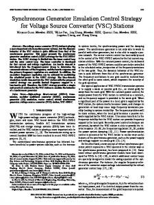
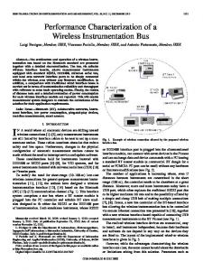
L d = L o + A , +Bo + ( 3 A 2 / 2 ) , & + A , +BO - ( 3 A , / 2 ) . 3. CALCULATION OF DISPLACEMENT ANGLES AND COMMUTATION ANGLES In the subsequent development, the following assumptions are made: 1) Only fundamental magnetic fiuxes are considered; 2) Load inductance is large enough to have direct current without pulsation in the load: 3) The speed of the generator rotor is constant. 4) There is one damper winding each on the d and q axes. 3.1 OPERATION MODE 1 The synchronous generator has two stator windings shifted by x 1 6 elec. rad, which with their bridges are connected in series, as shown in Fig. 1. Under this operation mode, the commutation process in the double-star synchronous generator is the same as in the common single Y-winding three phase machines, except that the phase currents in the second Y-windings lag the corresponding phase currents in the first Y-windings by x I 6 elec. rad as shown in Fig. 2, where the instant when the commutation starts from phase a1 to phase bl is taken as a time reference. When the stator windings are open and without load, the magnetic field axis is IC I 2 elec. rad ahead of a stator winding in which the induced voltage reaches its maximum value. When
Lp =
Neglecting the resistanceS of the armature windings and substituting eqn. (6) in eqns. (1) and (4). the phase voltage drops in the stator windings are given as
Fig. 1 Operation mode 1
615
where the integration constant K is calculated by initial conditions,t=O,0=6-rrI6.i =O.as K = ~ C ~ COS(^^--;)+ Z L K
--
#I
icl.
,- - -, - '-
- ?-
- -
-'3 -
-
-\ -
\ -- -
- 7 ' -I - -
'
' I '
- -\ - -
* wt
e P O t +5+11%16
(8)
From Fig. 2, the s t d n g and terminal conditions .during the C O ~ U t a t i o nperiod ate:
= vbl
ial=IL-i ,ibl=i , i c l = iaz= IL , i b 2 = 0 . i c 2 = - z L where i is the cycle current between phases (I 1 and b 1. Substituting eqns. (9) in the fundamental equations (3). gives:
6E
B E
J
COS
6
(14)
w
Fig. 2 Current waveforms in operation mode 1 the generator is carrying a load, the maximum value of the induced voltage is shifted by 6 elec. rad due to the influence of the PfmaWG reaction. Taking the axis of phase a1 as a space refmnce. the rotor angle at any instant is given as
"a1
sin 26 ] +
OD1
-5
cos ( 0 At the instant the commutation starts, w t = 0 , i = 0 , dildt = 0, 8 = 11% + 6 . Then eqn. (10)
When the commutation process finishes, w t = y , i = 1,. and eqn. (13) becomes
= - 6 E cos ( y + 6 ) I w + K The commutation angle y can be calculated from eqn. (15-a). Neglecting subtransient saliency, let Li' = Li', or C , = 0. and the expression of the commutation angle is given as y .= cos-' [ cos 6 -
2 0 Z L (0,- C O 1 1-6 .(SE
(15-b)
3.2 OPERATION MODE 2 The synchronous generator has two stator windings shifted by x I 6 elec. rad, which with their bridges are connected in parallel, as shown in Fig. 3. Under this operation mode, the commutation proccss does not undergo from one phase to another in the Same Y-windings, but from two phases in one Y-winding to two phase8 in the other Y-winding. According to the time reference selected in Fig. 4, when o t = 0. supply of the load current ZL is changed from phases b2 and c2 in the second Y-windings to the phases a1 and bl in the first Y-windings. During this period the c h u i t condition is shown in Fig. 5. The various phase currents under this operation mode are shown in Fig. 4. Taking the axis of phase a1 as a space reference, the rotor angle at any instant is given as
Based on Figs. 4 and 5, for o t between 0 and y, and
y