Performance of multi level error correction in binary holographic meniory Jay C. Hanan: Tien-Hsin Chao, George F. Reyes Jet Propulsion Laboratory, California Institute of Technology, CA, USA
ABSTRACT At the Optical Computing Lab in the Jet Propulsion Laboratory (JPL) a binary holographic data storage system was designed and tested with methods of recording and retrieving the binary information. Levels of error correction were introduced to the system including pixel averaging, thresholding, and parity checks. Errors were artificially introduced into the binary holographic data storage system and were monitored as a function of the defect area fraction, which showed a strong influence on data integrity. Average area fractions exceeding one quarter of the bit area caused unrecoverable errors. Efficient use of the available data density was discussed. Keywords: error correction, holographic memory, data storage, parity, bit matrix, particle analysis
1. INTRODUCTION ’
-~
xwphic Memory
-2
H uliving force iniproving digital storage technology is data density. Given equai data transfer rates and envlronmental
compatibility, the more bitsivolume the better the device. The theoretical data density lirmts of holographic memory, where the data may be stored m a volume, far exceed the theoretical data density limts of current technology such as magnetic disks, where information IS confined to a surface area. The Jet Propulsion Laboratory (JPL) is currently developing a new holographic memory system with performance characteristics including: readrewrite capability, high-density, high transfer rate, non-volatility, compactness, and radiation resistance. These characteristics are selected to meet requirements for data storage needs for both NASA’s space missions and co”xrcia1 applications. 1,2 ’3 ’4’5’6’7’8 ’9 NASA’s hture missions would require massive high-speed onboard data storage capability to support Earth Science missions. With regard to Earth science observation, a 1999 joint JPL and Goddard Space Flight Center (GFSC) (“The+HighData Rate hstmnient Study”) has pointed out that the onboard science data jcoliected by high date rate instruments such as hyperspectral and synthetic aperture radar) stored between downlinks would be up to 40 terabits (Tb) by 2003. However, onboard storage capability in 2003 is estimated at only 4 Tb which is only 10% of the requirement. By 2006, the storage capability would fall further behind and would only be able to support 1% of the onboard storage requirements. The volume nature of holographic data lends itself to a form of sectoring data structures across pages. Each page is given an angular address and contains a two-dimensional array of data. At JPL a binary holographic data storage system (BHDS) was constructed and tested with methods of recording and retrieving the binary information. Levels of error correction were introduced to the system and their perfomiance is reported here.
1.2 Error Correction An exainple of standard error correction in memory applications requires the dedication of a bit to each byte that may be checked. This “9”” bit may be assigned a value based on the sum of the byte, such as ‘on’ for odd and ‘off for evenparity. Checking parity allows errors in data to be discovered and, in some cases, corrected. For Holographc Memory, a similar error correction method may be employed. Every 9” bit may be dedicated to checking the sum of the previous 8 ‘Corresponding author; electronic mail:
[email protected]; phone 8 18-354-4820
bits, however since the data is stored in pages and may be represented as a binary matrix, other more efficient error checking methods may be employed. For the experimental system described below, the most basic form of error correction (or prevention) is to increase the signal per bit-a form of bit averaging. As this is a less efficient form of error correction, its use can be minimized to keep data density large. However, in cases were transfer speed and data integrity outweigh information density concerns, the ability to dynamically alter the bit averaging level can play a valuable role. A more efficient error checking scheme increases the data density without substantial loss of data integrity. Selecting this scheme requires consideration for the hardware peculiarities and the data format.” For example, based on measured dynamic range, the data stability is typically greatest toward the geometric center of the page where beam flatness is greatest; thus a measurement of errors toward the center of a page will provide less information on the likelihood of errors toward the edge of a page. If we assume the converse is true, then a reduction in the number of checksums and a corresponding increase in data density may be realized through an edge weighted page based error checking method. A simple page based error checking method is outlined in Figure I below, Input Data Matrix
A)
Output Data Matrix From “Read”
ROW
p;:sy 0
1
0
1
1
0
0
0
1
1
)‘
Row Parity Checks
+
Check = 0, No error
0
1
1
0
I
1
Column Parity Bits
Parity Check on Data Matrix
1
D>
0
1
Corrected Data
Read 0
1
0
1
1
0
0
0
1
Column Parity Checks
Figure 1. A schematic diagram of error correction using the L-Code on a 3x3 matrix. Extension to larger data matrices provides a simple error correction code first tested with the holographic system. In the example above, an input data matrix of 3 x 3 bits along with its parity bits is displayed at A). In B) an example read is demonstrated with an error in the upper left bit. The error is discovered in C) with the parity check. In D) the error is corrected without re-reading the data. This scheme extends to N x M page matrices. The N x M matrix can be
subdivided for optimal data density under expected noise conditions. Further, introducing a whole page parity check provides an additional data verification step. Since the parity bits lie along one column and row, they can be placed in the form of an “L”; hence this method of error correction will be referred to as the L-code.
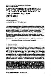
2. METHODOLOGY 2.1 Laboratory System The current laboratory setup allows analysis of all bits to determine the expected noise characteristics of the BHDS. The analysis is performed using custom LabVIEW based analysis software. The arrangement of parity bits will be determined based on analysis of these noise characteristics. Beam steering technique, image sensor performance, and other components factor into the total noise characterizes of the fmal system. Further evaluation of improved components will continue as the technology develops. The BHDS system has two main branches. One branch is used for retrieving stored information (read) and both branches are used for storing holographic information (write). The distinctive components of the read branch are the niultiplexing device and the photo detector for a data input component. While several technologies may be used for multiplexers, the BHDS uses a piezoelectric steerable mirror. For detailed error analysis a charge coupled device (CCD) was used to retrieve holograms from the photorefractive crystal. While this analysis employed an Fe doped L i m o 3 crystal, the results are applicable to other storage media. Along with intersecting the photorefractive crystal writing holograms, the second branch includes a spatial light modulator (SLM) in order to impart the page information onto the source laser beam (see the labeled photograph Figure 2).
LA,SE bean1
Figure 2. Photograph inclcding labe!ed components of a Binary Holographic Data Stcage (BEDS) system. ‘%e !ax: beam marked by green arrows is split into two branches. For reading data, only one branch (short dash) is on. For writing, both branches are on creating a hologram of the SLM plane with two beam interference in the photorefractive material. 2.2 Ezperimental Procedure A method was developed for testing error tolerance in the system. In the case of field use, the source of errors may be unlcnown. An advantage of holographic memory is the capability to dynamically reconfigure the page to compensate for defects. Thus, in the laboratory, sources of error are typically nlinimized or eliminated. However, for ths analysis, errors were intentionally introduced during the write procedure to test the multiple forms of error correction.
Errors were simulated in the device using a damaged SLM. Damage to the SLM included 45 spots, some minor scratches and other defects disrupting the intensity from the SLM. The same defect plane was used for all measurements. Since the size and arrangement of the defects were constant, the effect of defect area fraction was investigated by adjusting the areaibit. The area of bits was increased by incrementing the number of SLM pixelshit, i z x n pixelshit where, n = 2, 3, 4, 5, 6, and 7. Thus, five separate bit areas were tested against the constant defect plane giving five average defect area fractions, [average defect area] / [bit area] (See Table I). This increase in bit area was expected to reduce the number of observed errors-a first level of error correction in the device. A second, more efficient level of error correction is available through the use of parity checks (see 9 1.2). Two error correction methods were used on the page arrays. The fEst was the simple L-code error correction method using only one “L” per page. The second is a more efficient method developed at Caltech called the X-Code.” Both of these codes were tested on a 640x480 pixel’ representative portion of the data plane at each value of iz. T h ~ sformat coincides with the format of the CCD mounted to the BHDS for purposes of testing. While the full data density of the system cannot be read by the 640x480 pixels’ CCD, the number of bits observed at each scale provides representative area of the page for analysis. For the purpose of this experiment, bits were defined as on if their average intensityibit exceeded the threshold value, 800 out of 1024 (10 bit CCD), where the source laser power was optimized for best use of the available dynamic range. In practice, an optimal threshold value depends on several factors affecting the background intensity including the number of pages recorded. In practice a dynamic threshold method can be employed to further improve error tolerance; constant thresholding was used in this case to enable a germane comparison between the observed bit areas.
As expected more errors were observed as n decreased (see Table I). For n = 7 no error bits were observed. The number of error bits remained small down to n = 4. At JZ = 3 a significant increase in error bits was observed concluding with the greatest number for n = 2. Both the L-Code and the X-Code were able to recover data from errors up to n = 4. At n = 3, where on average 31% area of the affected bits are obscured by defects, the L-Code was able to recover more than half of the errors and the X-Code nearly three-quarters (Table I).
n (pixels) 7 6 5
4 3 2
Defect Area Fraction
8% 10% 14% 20% 31 %
56%
Raw Reconstruction (Error BitdTotal Bits) None Detected 0.22% 0.1 1Yo
0.13% 0.87% 1.13%
L-Code Correction
X-Code Correction
(Improvement)
(Improvement)
100% 100% 100% 52 % 6%
100% 100% 100% 74 %
48%
As n decreases and the error density increases and clustering of errors became more frequent. These clustered errors cannot be corrected by the L-Code. However, the number of errors increases non-linearly with defect area fraction to the degree that both error correcting codes failed at the same i z 5 3 (see Figure 3).
1.2% 1.0%
1
x
,
No Correction X-Code Correctiog
X
I
._
i
X
n=3
0.2%
x
-1
x 0.0% k
5%
E
-
-
x B
15%
r
L
25%
35%
45%
55%
Defect Area Fraction Figure 3. Graph depicting the increase in error bits as a function of increasing defect area fraction. Error correction from both the X-code (shown) and the L-Code (not shown) reduces the error to a non-detectible limit for defect area fractions of 20% or less.
4. CONCLUSIONS Errors were artificially introduced into a binary holographic data storage system (BHDS) constructed at the Jet Propulsion Laboratory. Data was stored in binary page format to the BHDS. The intentionally introduced read errors were monitored as a function of the defect area fraction. Defect area fraction showed a strong influence on data integrity with average area fractions exceeding one quarter of the bit causing unrecoverable errors-regardless of tested error correction schemes. Operation close to this one quarter level provides the most efficient use of the available data density. Successful data storage and recovery was performed at this level. Of the two error codes tested the X-Code corrected more errors suggesting the X-Code provides a greater margin of safety for data integrity; however, both codes tested provided similar practical performance.
The research described in this paper was carried out at the Jet Propulsion Laboratory, Califomia Institute of Technology, under a contract with the National Aeronautics and Space Administration. Support of the research was provided by White Sands Missile Range.
REFERENCES
1. T. H. Chao, G. F. Reyes, H. Zhou, D. Dragoi, J. C. Hanan, “High-density Holographic Data Storage,” Proceedings of Interizational Symposium on Optical memoiy 2001 PP.248-249, Taiwan, Oct. (2001). 2.
‘f H. Chao, J. C. Hanan, G. F. Reyes, “High density high data rate holographic memory using a MEMS mirror beam
3.
K.F.Strauss, T. Daud, “Overview of radiation tolerant unlimited write cycle nonvolatile memory,” Proc. 2000
steering device.” NASA NTR-40785 (2003).
4. 5.
6. 7. 8. 9. 10. 1:.
IEEE Aerospace Conference, vol. 5, pp. 399-408, 18-25 March (2000). W.Schober, F.Lansing, K. Wilson, E. Webb, “High Data Rate Instrument Study”, JPLpublication 99-4. T. H. Chao, H. Zhou, G. F. Reyes, JPL “Compact Holographic Data Storage System,”, Proceedings of Eighteenth IEEE Symposium on Mass Storage System in cooperation with the Ninth NASA Godda7.d Coilference on Mass Storage Systems and Technologies, April. (2001). T. H. Chao, H Zhou, G. F. Reyes, “Advanced compact holographic data storage system,” Proceedings of Nonvolatile memory technology symposium 2000, pp. 100-105, November, (2000). T. H. Chao, G. F. Reyes, H. Zhou, D. Dragoi, J. C. Hanan, “Nonvolatile Rad-Hard Holographic Memory,” Proceedings of Non-volatile memory Technology Symposium 2001, pp. 12-17, San Diego Ca, Nov. (2001). T. H. Chao, “Advanced Holographic Memory-AIST-99-0057-FinalReport” Prepared for NASA EST0 AIST, Nov. (2002). D. Dragoi, T. H. Chao, “Radiation test of LiNbO3 photorefractive crystal,” JPL report (2002). H. Pishro-Nik, N. Rahnavard, F. Fekri, “Non-uniform Error Correction Using Low-Density Parity-Check Codes” IEEE Transaction on I?zfori?zationTl’zeory (2003). L. EL,J. Bmck, “X-Code: MDS Axray Codes with Optimal Encoding.” iEEE li.ans. on Ityhnatioiz Tlzeoi-y, Jan. (1999).