Oct 3, 2007 - a processor under thermal constraints for a given task sequence. We ... of dynamic thermal management (DTM), where the processor is.
Performance Optimal Processor Throttling Under Thermal Constraints ∗
Ravishankar Rao and Sarma Vrudhula Consortium for Embedded Systems Arizona State University Tempe, AZ 85281, USA {ravirao,
vrudhula}@asu.edu
ABSTRACT
Keywords
We derive analytically, the performance optimal throttling curve for a processor under thermal constraints for a given task sequence. We found that keeping the chip temperature constant requires an exponential speed curve. Earlier works that propose constant throttling only keep the package/case temperature constant, and are hence suboptimal. We develop high-level thermal and power models that are simple enough for analysis, yet account for important effects like the power-density variation across a chip (hotspots), leakage dependence on temperature (LDT), and differing thermal characteristics of the silicon die and the thermal solution. We use a piecewiselinear approximation for the exponential leakage dependence on temperature, and devise a method to remove the circular dependency between leakage power and temperature. To solve the multitask speed control problem, we first solve analytically, the single task problem with a constraint on the final package temperature using optimal control theory. We then find the optimum final package temperature of each task by dynamic programming. We compared the total execution time of several randomly generated task sequences using the optimal control policy against a constant speed throttling policy, and found significantly smaller total execution times. We compared the thermal profiles predicted by the proposed high-level thermal model to that of the Hotspot thermal model, and found them to be in good agreement.
thermal management, throttling, thermal model, power, leakage dependence on temperature
1. INTRODUCTION As technology scaling puts hundreds of millions of transistors on ever shrinking dies, both the total power consumption and the power density of these chips have risen exponentially. Power (especially leakage) and thermal issues have greatly curbed the increasing clock speeds of chips. In recent years, processor manufacturers have deployed a variety of techniques like power gating, sleep transistors, multiple cores, improved process technology, and microarchitectural refinements, all to limit the power consumption. In spite of these improvements, the worst-case power consumption remains high enough to require expensive cooling solutions to sustain it indefinitely. Most modern high-performance processors support some form of dynamic thermal management (DTM), where the processor is throttled if its temperature exceeds a specified threshold to avoid damaging the chip. As processor workloads only rarely result in worst-case power consumption, DTM allows a processor’s packaging and cooling solution to be designed for the average case. The throttling mechanism allows the processor to gracefully handle workloads with a mix of high and low power tasks by running low power tasks at full speeds, and the more intense ones at lower speeds. The ideal DTM strategy maintains the chip temperature at or below the specified maximum with minimum performance loss due to throttling.
Categories and Subject Descriptors C.4 [Computer Systems Organization]: Performance of systems— Modeling Techniques
1.1 Thermal and power models Previous works on DTM have operated at either at the architecural or system level. Architecture-level works [1–4] have explored the effect of various thermal management techniques (e.g. feedback control fetch throttling, task migration, localized voltage frequency scaling for multi-core processors) on SPEC benchmarks by using detailed power/performance/thermal simulators like Simplescalar, Wattch, PTScalar and Hotspot. The system-level techniques, on the other hand, have used high-level analytical power and thermal models to derive optimal or near-optimal DTM strategies [5–11]. Analytical results provide many advantages to system designers that are not available from low-level simulation tools. They can provide bounds on the system performance under thermal constraints and they can serve as good nominal models for designing feedback control systems for DTM. Different control schemes can be compared more readily using high-level models, especially for long duration workloads for which low-level simulation is expen-
General Terms Algorithms, Performance, Theory ∗ This work was supported by the Consortium for Embedded Systems at Arizona State University and by National Science Foundation grants ITR-0205227 and CSR-EHS-0509540.
Permission to make digital or hard copies of all or part of this work for personal or classroom use is granted without fee provided that copies are not made or distributed for profit or commercial advantage and that copies bear this notice and the full citation on the first page. To copy otherwise, to republish, to post on servers or to redistribute to lists, requires prior specific permission and/or a fee. CASES’07, September 30–October 3, 2007, Salzburg, Austria. Copyright 2007 ACM 978-1-59593-826-8/07/0009 ...$5.00.
257
sequence of tasks (having different power profiles), subject to an upper bound on the maximum chip temperature. At the microarchitecture level, a feedback control approach to this problem was proposed in [24], where a controller adjusts the speed dynamically based on the hottest chip temperature. The actual shape of the control trajectory was however, not a focus of the latter work. At the system level, simple lumped thermal and power models were used to solve the above problem, but for a single task [5,9]. These works predicted that a constant speed curve would keep the chip temperature at the specified maximum. We show that due to the differing thermal characteristics of the die and the package, an exponentially time-varying speed curve is needed, and results in lower performance loss than the constant throttling. Also, our work accounts for the effect of a task’s power consumption on future tasks. For example, a task could leave the package at a sufficiently high temperature so that the next task would be forced to throttle and suffer lower performance. We propose a twostage optimization procedure that selects the intermediate package temperature between tasks, and then adjusts the individual tasks speeds to meet those package temperatures. Recently, [10] used simpler power and thermal models to devise energy efficient task scheduling heuristics in the presence of thermal constraints. Our work focuses on performance optimization, which is often the objective in high-performance server processors. While our goal in this paper is to find performance-optimal speed control techniques for a given task sequence, we plan to extend this framework to devise thermal-aware task scheduling heuristics. We have organized the rest of the paper as follows. Section 2 describes the task, thermal and power models used. In Section 3, we obtain preliminary results that are then used in Section 4 to obtain the optimal speed profile. In Section 5, we compare the effectiveness of the optimal speed profile against a constant speed throttling, and also verify the thermal profiles with Hotspot. Section 6 concludes the paper.
sive. Further, analytical results present expressions that relate performance metrics (like the execution time of a task) to design parameters (like the leakage power consumption, thermal resistance of the package, etc). Such expression provide greater insight for designers to perform tradeoffs. Finally, analytical results for systemlevel DTM (for example, heuristics for thermal-aware task scheduling) are amenable for software implementation in the operating system, while architecture-level DTM is best suited for hardware implementations. However, the models used in the existing system-level approaches were very simple, and did not capture one or more of the following important effects: (1) the variations of power-density over different chip blocks, which leads to hotspots [2], (2) leakage dependence on temperature (LDT), which is significant for 65 nm and beyond [8, 12], and (3) the differing thermal characteristics of the die and package. For example, [5, 6, 8–10, 13, 14] use a single thermal resistance and capacitance, and hence cannot account for (3). The methods described in [6, 9, 10, 14] modeled only the full-chip power using lumped RC circuit models and ignored the powerdensity variations across the chip, and [5, 7, 9–11, 14] neglected LDT. Thus, these approaches would not be able to accurately predict the chip temperature.
1.2 The need for high-level analytical models A compact thermal model of a processor was proposed in [2] that constructs an equivalent thermal RC circuit of the processor chip, the thermal packaging and the cooling system. This thermal model was implemented as a portable tool called Hotspot [2], which has been used in a variety of micro-architectural studies on thermal management. Hotspot constructs an equivalent RC circuit for a given floorplan. The circuit has one capacitance for each functional block (typically, around 20) and eleven for the package. Detailed power models [8, 15] have been proposed that model the static power of each functional block including its dependence on that block’s temperature. Unfortunately, these models are too complex. The Hotspot model for for the Alpha 21264 processor is of the order 31. This, together with the exponential LDT models, constitute a system of coupled non-linear differential equations which cannot be solved analytically. But, why do we need analytical thermal and power models? There is a large body of work on processor dynamic speed control and task scheduling to achieve energy efficiency under performance constraints (see [16–21] for some representative works). Due to the simple cubic relationship between dynamic power and speed, researchers were able to propose efficient heuristics and in some special cases, polynomial time algorithms, to solve these challenging problems. Similarly, high-level analytical battery models were used in [22,23] to derive task sequencing and voltage scaling heuristics that maximize battery lifetime. However, due to the complexity of block-level thermal models, there is no known expression that relates the temperature of the hottest chip block to the chip speed and task power parameters. Hence, it is very difficult to solve problems of this kind (like task sequencing and throttling to minimize total execution time, throughput optimal stochastic speed control for sporadic workloads, etc.) when thermal constraints are added. In this paper, we propose a high-level thermal model that is an approximation of the Hotspot model, and represents an acceptable tradeoff between accuracy and analytical tractability.
2. SYSTEM MODEL 2.1 Task model Thermal issues are most critical for processors used in highperformance servers. Such servers are typically assigned a batch of tasks to be executed on a first-come first serve basis (i.e. a queue). Server workloads can consist of short sporadically arriving tasks that can be serviced at the same rate as they arrive (like web page requests), or small sets of long duration workloads that arrive quickly but take a long time to be serviced (e.g. scientific/industrial simulations). As the latter set of jobs are more performance (and hence thermally intensive), we use it as our task model. We further restrict our analysis to tasks whose durations are in the range of ten seconds to ten minutes, so that they are comparable to the largest thermal time constant in the processor’s thermal equivalent circuit (which is around one minute). Tasks that are smaller than ten seconds do not cause substantial temperature increase and hence do not benefit from the proposed optimization, while tasks longer than ten minutes are better suited for steady-state analysis to determine the optimum (constant) speed control [25]. We assume that the server consists of a single-core processor that is assigned a sequence of L tasks to be executed as fast as possible, subject to thermal constraints. The number of cycles N to be executed, and the power consumption characteristics 1 of each task is assumed to be known a priori, making this a static optimization.
1.3 Performance optimal throttling
1 The power of each functional block as a function of the degree of throttling and block temperature.
We use this thermal model to derive analytically the time-varying speed control that minimizes the total execution time of a given
258
2.2 Thermal model
Chip
We developed a high-level thermal model based on the Hotspot thermal RC circuit model [24]. Hotspot uses an analogy between electrical circuit phenomena and heat transfer phenomena. The equivalent circuit consists of one node for each chip functional block, and eleven blocks for the package. Heat transfer through conduction between neighboring nodes is modeled through connecting thermal resistances, and the heat storage in each node by thermal capacitances. Each chip node is also connected to a current source that models its power consumption, and this power is dissipated as heat with a uniform power density over the block’s surface. For the Alpha 21264 processor, there are M = 20 functional blocks, and the resulting Hotspot circuit has 31 capacitances. The 2 All
P1 T1
Pi
R1
Ri
Pl Tl
Ti
Package Cp
Rl
Tp Rp
Internal Ambient
Figure 1: High level thermal model of a processor.
temperatures are relative to the internal ambient temperature.
Symbol U Umax u N M L Pi Ps,i Pd,i � Ps,i � Pd,i Ti ki ζi Ri h Th � Ps,h � Pd,h ζh Rh Ps� Pd� P� (u) � Pmax Tp Tc,max Tp,max ur (t) ur0 ur,ss Tpi Tp f Tp,ss τr Rp R�p Cp G tm tc tf
Block i
number of thermal resistances is more than 31 due to lateral resistances on the chip between neighboring functional blocks. This large number of parameters make it difficult for analysis. On examining the parameter values of the Hotspot circuit for the Alpha 21264, we made the following approximations:
Meaning Processor clock frequency Maximum processor clock frequency Normalized processor clock speed Number of cycles to be executed by a task Number of functional units in the chip Number of tasks in the given task sequence Actual power consumed by block i Actual leakage power of block i Actual dynamic power of block i at full speed Apparent leakage power of block i Apparent dynamic power of block i at full speed Temperature of block i 2 Slope of leakage vs temperature curve for block i Leakage power factor of block i Vertical thermal resistance of block i Index of hottest block Temperature of hottest block Apparent leakage power of hottest block Apparent dynamic power of hottest block at umax Leakage power factor of hottest block Vertical thermal resistance of hottest block Total apparent leakage power Total apparent dynamic power at maximum speed Total apparent power at speed u Total apparent power at speed umax Temperature of package Maximum allowed chip temperature Package temperature when u = 1 and Th = Tc,max Optimum throttling curve Initial value of throttling curve Steady-state value of throttling curve Initial package temperature Final package temperature Steady-state value of package temperature Time-constant of throttling curve Actual package thermal resistance Apparent package thermal resistance Package thermal capacitance A parameter that relates R�p to R p Time at which package heats up to Tp,max Time at which all task cycles are completed Task completion time
1. The thermal resistance Rconv and capacitance Cconv of the cooling system are much larger than that of the other components of the package. Also, the thermal constraint is specified for the chip, and not for any component of the package. Hence, the package can be well approximated with a reduced first order model. 2. The lateral resistances between chip units were at least four times larger than the vertical resistances that connected chip units to the package, i.e. most of the heat flow in the chip occurs vertically. Hence, we neglect lateral resistances on chip. Note that this assumption does not eliminate the occurrence of hotspots and thermal gradients as they are mainly caused by differences in power density among chip blocks. 3. The thermal RC time-constant of the die was of the order of ten milliseconds, while that of the package was of the order of one minute. This means that the silicon die cannot store as much heat as the packaging and cooling solution, and its temperature changes much faster than that of the package. As the task durations discussed above are much larger than the die’s time-constant, but are comparable to the package time-constant, we can ignore the die thermal capacitances.3 With the above approximations, we obtain the high-level thermal RC circuit shown in Figure 1. The package is reduced to a first order RC circuit. Each chip block i is modeled by a current source Pi (representing its power consumption) and a thermal resistance Ri (representing conduction vertically through the silicon). The values for Ri were set equal to the vertical resistance connecting each chip block to the spreader-top block in the original Hotspot circuit. The voltage across the capacitance Cp (Ci ) is the temperature (relative to the internal ambient) of the lumped package Tp (ith chip block Ti ). LDT makes the current source Pi of each block dependent on its voltage Ti .
3 However, we do use the concept of die thermal capacitance in Section 3.1 to remove the circular dependency between leakage and temperature.
Table 1: Notation.
259
2.3 Power model Total chip static power (W)
70 60 50 40 30 20
Tc,min
40
Tc,mid 50
Tc,max
60 70 80 90 Chip Temperature (deg C)
100
110
Figure 2: Leakage vs temperature and piece-wise linear approximation. duration. We then have Ci dTi (t)/dt = −(Ti (t) − Tp )/Ri + Pi (u, Ti (t))
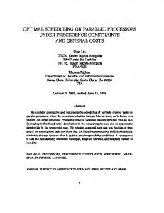
Piecewise-linear approximation for LDT. Figure 2 shows
(2)
From Section 2.3, the power consumed by block i is
the total leakage power of a processor versus the chip temperature, and is based on the leakage models in [8]. The leakage here doubles every 20◦ C. From this figure, it can be seen that the exponential LDT model can be approximated well by a piecewise linear model. ( Ps,i,mid − ki1 (Tc,mid − Ti ), Tc,min < Ti ≤ Tc,mid , (1) Ps,i = Ps,i,max − ki2 (Tc,max − Ti ), Tc,mid < Ti ≤ Tc,max ,
Pi (t) = Ps,i,max − ki (Tc,max − Ti ) + u(t)Pd,i .
(3)
Substituting for Pi from (3) in (2) results in a linear ordinary differential equation (ODE), which we solve to get Ti (t) = Ti (0)e−βi t + (αi /βi )(1 − e−βi t ),
(4)
where αi = (1/Ci )(Ps,i,max − ki Tc,max + uPd,i + Tp /Ri ) and βi = (1/Ci ) (1/Ri − ki ). If ki > 1/Ri for any chip block, that block will experience thermal runaway. This is a sufficient but not necessary condition. But, if ki ≤ 1/Ri for all chip blocks, the chip temperatures Ti → αi /βi . This is because, for time periods of length t ∼ 0.1R pCp , we have βi t ∼ (0.1R pCp )/(RiCi ) ∼ (0.1×100 s)/(10 ms) = 103 , so that e−βi t → 0. Assuming the chip design ensures no thermal runaway for Ti ≤ Tc,max , we now have by the end of the time period t = 0.1R pCp ,
for all i ∈ {1, . . . , M}. Here ki1 and ki2 quantify the sensitivity of leakage to temperature of the ith block in the two temperature ranges. Tc,min is usually chosen to be the ambient temperature, Tc,max as the manufacturer specified thermal threshold for the processor, and Tc,mid chosen suitably to have the linear approximation lie above but close to the exponential curve. In the interest of clarity, we will present the forthcoming analysis as though there is a single set of leakage coefficients ki , instead of using one for each temperature range. The results in Section 5 however, were obtained using the two-piece linear leakage model, with the correct set of coefficients employed depending on the instantaneous value of the chip temperature.
3.
Accurate Linear fit
80
The active power Pi consumed by block i has two parts, dynamic and static. In this work, we model the dynamic power consumption as a linear function of the speed u. Most of the DTM mechanisms (including Dynamic Frequency Scaling (DFS), clock gating, and fetch throttling, but excluding Dynamic Voltage and Frequency Scaling (DVFS)) involve a linear reduction in power with the degree of throttling (which we call the speed). Hence, using a linear power-speed model covers most of them. A majority of modern processors (even those that have DVFS) use a mechanism with linear power-speed relationship for DTM purposes [26, 27]. Further, as supply voltages reduce with technology scaling, there is lesser scope for DVFS to scale down voltages. Hence, we use DFS as the DTM mechanism in this work, and we define the speed u as the normalized clock frequency U/Umax . The dynamic power as a function of speed is then given by u Pd,i where Pd,i is the dynamic power at the maximum speed u = 1. The static power Ps,i is an increasing function of the temperature of the block, Ti [8, 15]. Thus, the block power is a function Pi (u, Ti ) of the speed and block temperature. However, we know from the thermal model that Ti in turn depends on Pi , thus creating a circular dependence. We show how to resolve this dependence in Section 3.1.
� � Ti (t) ≈ αi /βi = ζi Tp (t) + (Ps,i + u(t)Pd,i )Ri ,
TM
PRELIMINARY RESULTS
In this section, we obtain many preliminary results that we then use to find the optimal speed profile. (1) In Section 3.1, we devise a method to remove the circular dependency between leakage power and temperature by expressing both of them in terms of the package temperature. (2) The resulting expression for power consumption is used in Section 3.2 to obtain a differential equation for the package temperature. We then redefine certain groups of parameters into “apparent” static and dynamic powers, and apparent thermal resistance, so that the differential equation has the same form as it would without LDT. (3) In Section 3.3, we show how to identify the hottest block in a chip for a given task.
Ri
Ti
Ci
Pi (u, Ti )
P1 (u, T1 )
3.1 Decoupling leakage and chip temperature We first note that due to the relatively large package time constant, Tp (t) changes much slower than Ti (t). For time durations of the order of 0.1R pCp , Tp (t) can be assumed constant. Figure 3 shows the effective thermal RC circuit for block i over such a time
RM CM
PM (u, TM )
T1
(5)
Tp
R1 C1
Figure 3: Effective thermal RC circuit for decoupling leakage and chip temperature.
260
Chip
u(t) t
R pC p 10
Block i
Chip
P1 T1
Pi Ti
Pl Tl
R1
Ri
Rl
Package Cp
Ti (t)
P�
P�
Package
Tp
Cp
Rp
Tp R�p
(b)
Ti (t), Tp (t) Internal Ambient
(a)
Tp (t)
t
Internal Ambient
Figure 5: (a) Complete high-level thermal model, (b) Effective circuit for computing the Tp .
Figure 4: Different response of chip and package temperature to sudden changes in processor speed. package temperature Tp is given by the following equation dTp (t) dt
where we have introduced the following quantities: ζi � 1/(1 − � � ζ (P ki Ri ) (leakage power factor), Ps,i i s,i,max − ki Tc,max ) (appar� ent static power), and Pd,i � ζi Pd,i (apparent dynamic power). The above equation suggests that the effect of the initial chip temperature Ti (0) decays away by time 0.1R pCp , and the chip temperature is now dependent on the package temperature Tp (t) as well as the instantaneous speed u(t). Figure 4 illustrates the thermal response of the chip and package to sudden changes in the speed u(t). Over a time period 0.1R pCp , the package temperature Tp (t) changes very little, but the block temperature changes faster due to the small capacitance value of Ti . The exponential behavior of Ti (t) over this small interval is predicted by (4). By the end of this interval, the chip temperature has mostly settled to the value αi /βi , and now continues to change slowly as Tp (and hence αi changes). If the speed changes suddenly again, transients in Ti appear and fade as before. The advantage of using the “apparent” quantities defined above is that the resulting equations have a form that is close to what we would have if there was no LDT. We now show how Ps,i can be expressed independent of Ti , thus removing the circular dependency. Starting from Ps,i = Ps,i,max − ki (Tc,max − Ti ), we substitute for Ti . After some manipulation, it can be shown that the total power of block i is given by
� � + u(t)Pd,i + (ζi − 1)Tp (t)/Ri Pi (t) = Ps,i
=
−
N Tp (t) 1 X + Pi (t) R pCp Cp i=1
– N » Tp (t) (ζi − 1) Tp (t) 1 X � � Ps,i + u(t)Pd,i (7) + + R pCp Cp Ri
=
−
=
˜ Tp (t) 1 ˆ � + Ps + u(t)Pd� + GTp (t) − R pCp Cp
=
−
i=1
Tp (t) Ps� + u(t)Pd� + , R�pCp Cp
(8) (9)
where R�p � R p /(1−GR p ). The significance of (8) is that in spite of LDT, one can compute the package temperature by solving a first order linear ODE. To do so, we first compute the total apparent power consumption P� = Ps� + uPd� of the chip, and the apparent package thermal resistance R�p . Then, Tp is simply the response of a first order thermal RC circuit with input current P� , thermal resistance R�p and thermal capacitance Cp , as shown in Figure 5(b).
3.3 Identifying the hottest chip block The hottest block h is defined as the one that maximizes Ti over i = 1, . . . , N. From (5), we can see that hottest block of a chip corresponds to the one with the largest power-resistance product (i.e. largest power density). This would, in general, be a function of the speed, and is given by h(u) = {h|Ph (u)Rh = maxi=1,...,l Pi (u)Ri }. In general, different blocks within a given core can become the hottest depending on the speed. However, we have found that this is usually not the case, and that the hottest block at u = 1 (which is henceforth denoted by the index h) remains the hottest at all speeds.
(6)
The chip power still depends on temperature, but of the package rather than the chip. We note that in the absence of LDT, ki ≡ 0, ζi = 1 ∀ i, and the above equations reduce to Ti (t) = Tp (t) + (Ps,i + u(t)Pd,i )Ri and Pi = Ps,i + u(t)Pd,i as expected.
4. THE OPTIMAL SPEED CURVE 4.1 The optimal throttling curve We first obtain the optimal throttling curve assuming the chip temperature has already reached Tc,max , and then analyze the case for arbitrary initial package temperature. Once the temperature of the hottest block Th reaches Tc,max (say, at time tm ) the processor must be throttled to maintain the maximum chip temperature at Tc,max . We set u(t) to equal the throttling curve ur (t) for all t > tm . Using (5), we get ” “ � � Rh . + ur (t)Pd,h (10) Tc,max = ζh Tp (t) + Ps,h
3.2 Package temperature computation
P � We first define the following quantities: Ps� � N i=1 Ps,i (Total P � apparent static power), Pd� � N i=1 Pd,i, (Total apparent dynamic
� � Ps� + Pd� (Total apparent power at u = 1), power at u = 1), Pmax PN and G � i=1 (ζi − 1)/Ri . Now, from the high-level thermal RC circuit obtained before (which is reproduced in Figure 5(a)), the
261
Substituting for Tp (t) from the above equation into (8), and rearranging terms, it can be shown that we get for all t > tm
form, and are derived in Section 4.3. Section 4.4 presents a solution methodology for the above problem. The resulting optimum initial ∗ ,T∗ and final temperatures, Tpi,k p f ,k can then be used to obtain the ∗ , T ∗ ,t). optimum speed profiles for the individual tasks u∗ (Tpi,k p f ,k
� � � � � � dur (t) Tc,max − Ps,h Rh − ζh Ps R p Pd,h Rh + ζh Pd R p − ur (t) = � R � R dt R�pCp Pd,h R�pCp Pd,h h h
4.3 Optimum speed control for a single task
The above first order ODE in ur (t) has the following solution ur (t)
=
ur,ss
�
τr
�
We first solve the problem with final package temperature constraint. Given a processor whose initial package temperature is Tpi and final package temperature must be Tp f , and given a task with known power parameters (Ps,i (Ti ), Pd,i (u), ki for all i = 1, . . . , N), how should the speed of the processor u(t) be chosen to complete a specified number of clock cycles N in the least possible time t f , while ensuring that the following constraints are met: Th (t) ≤ Tc,max and 0 ≤ u(t) ≤ 1 for all 0 ≤ t ≤ t f ? Denoting the number of cycles executed at time t as x(t), this problem can be formally stated as follows: Z tf tf = 1 dt, (18) min
ur0 e−(t−tm )/τr + ur,ss (1 − e−(t−tm )/τr ), where (11) � R − ζ P� R� Tc,max − Ps,h h h s p , and (12) � Pd,h Rh + ζh Pd� R�p R�pCp
� R Pd,h h
� R + ζ P� R� Pd,h h h d p
.
(13)
We note that ur0 in (11) must be chosen to satisfy the boundary condition Th (tm ) = Tc,max . By employing the above exponential speed profile, the hottest chip temperature Th is maintained at Tc,max , while the asymptotically approaches the value ` package temperature ´ Tp,ss = Ps� + ur,ss Pd� R�p . We can now see the advantage of using different thermal resistances to model the die and the package, when compared to a single lumped resistance. The latter model can only predict the package temperature, and in the event of a thermal emergency, will try to maintain the package temperature constant by reducing the speed immediately to a constant speed u ≈ ur0 [9]. However, by using the throttling curve ur (t), the package temperature can be allowed to change while still maintaining the chip temperature constant, thus obtaining better performance from the processor.
u(t),t f
s.t.
subject to,
(21)
0 ≤ u(t) ≤ 1 ∀ t.
(24)
The above formulation is a problem in optimal control [28], with a variable endpoint t f , two state variables x and Tp , fixed boundary conditions at both ends (20), (22), bounds on the control (24), and a mixed state-control point-wise inequality (23). The presence of the latter inequality makes the solution process complicated. In the interest of clarity, and due to lack of space, we omit the derivation, and instead present the final solution. First, we use (5) to compute the package temperature Tp,max when the chip reaches Tc,max when operating at maximum speed: ” i h “ � � Rh /ζh . + Pd,h Tp,max = Tc,max − Ps,h
(25)
Case 1: Tp0 ≤ Tp,max . The optimum policy operates at maximum speed until the chip temperature reaches Tc,max at time tm . Then, it employs the throttling curve ur (t) until the required X clock cycles are completed at time tc . Finally, it drops the speed to 0 to achieve the final package temperature Tp f at time t f . The throttling chooses ur0 = 1 to ensure that Th (tm ) = Tc,max . The optimum speed control is thus obtained as
Problem MULTI-TASK: {Tpi,k ,Tp f ,k , k=1,...,L−1}
(20)
(22) Tp (0) = Tpi , Tp (t f ) = Tp f , ” “ � � Rh ≤ Tc,max ∀ t, (23) + u(t)Pd,h ζh Tp (t) + Ps,h
Given a set of L tasks that must be executed in a given sequence, and given an initial package temperature Tp0 , we wish to find the speed control u(t) for each task such that the total execution time is minimized, and the maximum chip temperature is maintained below Tc,max . We note that the final package temperature Tp f ,k of task k is the initial package temperature Tpi,k+1 of task k + 1. As the execution time of a task is affected by its initial package temperature, we see that each task affects its future tasks’ performance by its choice of final package temperature. We now use the following technique to solve the multiple task speed control problem. We first derive analytically the optimum speed control technique under thermal constraints for a single task, for a given initial package temperature Tpi , and a given final package temperature Tp f . This gives us the optimum execution time t ∗f (Tpi , Tp f ), as well as the optimum speed control u∗ (Tpi , Tp f ,t), in terms of the unknown initial and final package temperatures. The optimum speed control in the absence of final temperature constraint is similarly derived to obtain the functions t ∗f (Tpi ) and u∗ (Tpi ,t). We then select the package temperatures between neighboring tasks in such a way that the total execution time of all tasks is minimized. Formally, we have: L−1 X
(19)
dTp (t) Tp (t) Ps� + u(t)Pd� + , =− � dt R pC p Cp
4.2 Optimal speed control for multiple tasks
min
0
dx(t) = u(t), dt x(0) = 0, x(t f ) = N/Umax � X,
8 > : 0, tc < t ≤ t f .
t ∗f ,k (Tpi,k , Tp f ,k ) + t ∗f ,L (Tpi,L ), (14)
k=1
Tpi,k+1 = Tp f ,k ∀ k = 1, . . . , L − 1,(15) Tpi,1 = Tp0 , (16) Tp f ,k ≥ 0 ∀ k = 1, . . . , L − 1. (17)
Here, tm is calculated using
We have used task subscripts for the t ∗f functions because they are different for each task (due to differences in number of clock cycles and power parameters). However, the functions all have the same
tm = R�pCp log
262
� R� − T Pmax p0 p � R� − T Pmax p,max p
! .
(26)
The area under the normalized speed curve u over [0,tc ] must equal X, or “ ” f (tc ) = tm + (1 − ur,ss ) τr 1 − e−(tc −tm )/τr +
ur,ss (tc − tm ) − X = 0.
4.4 Dynamic programming solution for multiple tasks Having solved the single task optimization, we return to the problem MULTI-TASK that we defined in Section 4.2. We now show that this problem has a property that makes it amenable for a dynamic programming solution. Given an initial package temperature Tpi,k , let the optimum total execution time for tasks k, k + 1, . . . , M be denoted as t ∗f ,≥k (Tpi,k ). Then, given the optimal initial package ∗ for task k, the optimum final package temperature temperature Tpi,k ∗ Tp f ,k can be computed as follows:
(27)
Solving the implicit equation (27) numerically gives tc . The optimum task completion time t ∗f is then ! Ps� R�p − Tpc ∗ , (28) t f = tc + τ p log Ps� R�p − Tp f
Tp∗f ,k = arg
R�pCp ,
and Tpc is the package temperature at time tc , where τ p = which is computed using ” ` ´“ Tpc = Tp,max e−(tc −tm )/τ p + Ps� + ur,ss Pd� 1 − e−(tc −tm )/τ p ” τr (1 − ur,ss ) � � “ −(tc −tm )/τr Pd R p e − e−(tc −tm )/τ p . (29) + τr − τ p
0≤Tp f ,k ≤Tc,max
h i ∗ t ∗f ,k (Tpi,k , Tp f ,k ) + t ∗f ,≥k+1 (Tp f ,k ) . (34)
Thus, the problem MULTI-TASK satisfies the principle of optimality as the sub-solutions of the optimal solution t ∗f ,≥k are themselves optimal solutions for their subproblems. If we discretize the range of package temperatures [0, Tc,max ] to, say Np levels, we can solve the above recursion using dynamic programming. To do so, we first construct a table with Np rows (corresponding to package temperature values) and M columns (corresponding to tasks in the given sequence). The cell (i, j) will store the optimal solution for the sub-problem with tasks j, j + 1, . . . , M, given an initial package temperature (i − 1)Tc,max /(Np − 1). The dynamic programming algorithm starts at cell (i0 , 1), where i0 is the discrete level that corresponds to package temperature Tp0 . It then finds the optimum final temperature by trying all possible cells in the second column, and computing the corresponding total execution times according to (34). Thus, it takes O(Np ) time to fill each cell in columns 1 to M − 1, and O(1) for each cell in the last column (as there is no final temperature constraint for the last task). As the size of the table is Np M, the running time of the dynamic programming algorithm is O(Np2 M). Note: In theory, the use of idle periods at the end of a task, while worsening the performance of that task, could improve the total execution time of the task sequence. Hence, the formulation MULTITASK. However, after performing simulations with thousands of random task sequences, we found that the optimum final temperatures for the MULTI-TASK problem were such that no idle periods were actually used at the end of any of the tasks. This means that we could simply compute the single task optimal speed policy without final temperature constraint independently for each task to achieve the global optimum execution time. This also reduces the running time from O(Np2 M) to O(M) as we do not need to use the dynamic programming solution any more. While we currently have no proof that this will always be true, we have not encountered a contradiction so far in our simulations.
It can be shown that if Tp f > Tpc for any task, the resulting total execution time of all tasks would be worse than if Tp f = Tpc , i.e. there is no performance benefit in heating up the package after the task is complete, which is intuitively satisfying. Hence, we only need to consider the cases where Tp f ≤ Tpc , which requires a cooling pe� R� < T riod t f − tc . We also note that if tm > X or if Pmax p,max , the p maximum chip temperature is not exceeded before the task completes, in which case, the optimum speed control reduces to ( 1, 0 ≤ t ≤ tc , ∗ u = (30) 0, tc < t ≤ t f . where tc = X, and t ∗f is calculated using (28).
Case 2: Tp0 ≥ Tp,max . If Tp0 ≥ Tp,max , we cannot use the speed u = 1 as that would raise the chip temperature beyond Tc,max . Effectively, tm = 0, and the optimum policy deploys the throttling curve ur (t) at time t = tm = 0, with the initial throttling speed ur0 again chosen such that Th = Tc,max , and is given by ” “ ” “ � � (31) Rh / Pd,h Rh . ur0 = Tc,max − ζh Tpi − Ps,h The required number of cycles X are completed by time tc , after which the speed drops to 0 to achieve the required final temperature Tp f at time t f . The optimum speed control is given by “ ” ( −t/τr + u −t/τr , 0 < t ≤ t , u 1 − e e r,ss c r0 (32) u∗ (t) = 0, tc < t ≤ t f . The area of the speed curve over [0,tc ] equals X, or “ ” f (tc ) = (ur0 − ur,ss ) τr 1 − e−tc /τr + ur,ss tc − X = 0.
min
5. RESULTS 5.1 Experiment setup
(33)
We first obtained the equivalent thermal RC circuit for the Alpha 21264 floorplan using the Hotspot tool [2]. We then applied the approximations mentioned in Section 2.2 to this Hotspot circuit and obtained our high-level thermal model. We modified the convection thermal resistance in Hotspot from 0.8 W/◦ C to 0.4 W/◦ C to better reflect the power-thermal characteristics of modern servergrade processors [26, 29]. This lower value represents improved packaging and cooling technology and was chosen to allow a chip maximum temperatures Tc,max = 110◦ C, and a steady-state power consumption (with throttling) of about 120 W. We set the maximum clock speed to be Umax = 4 GHz.
Solving (33) numerically gives tc . The task completion time t ∗f is obtained as above using (28) and (29). We note that if Tp0 = Tp,max , we get ur0 = 1, tm = tc = 0, and the two cases give the same solution.
Optimum speed control with no final temperature constraint:. For the last task in the given sequence, there is no final temperature constraint. It can be shown that the optimal speed policy for this case is obtained by simply omitting the last segment of the above speed profiles and setting t ∗f = tc , i.e. no cooling period.
263
Task 2
Task 1
Task 3
9
2
120 100 0
100
200
300 400 Time (s)
500
High�level Hotspot 100
200
300 400 Time (s)
500
100 0
High�level Hotspot 100
200
300 400 Time (s)
500
Task 2
Task 3
2
100
200
300
400 Time (s)
500
600
700
300
400 Time (s)
500
600
700
300
400 Time (s)
500
600
700
120 100 80
High�level Hotspot 100
200
110 100 90 0
600
Task 1
x 10
0
600
110 105
4
0 0
600 Power (W)
Power (W)
0 0
Max. temp. (C)
Speed (Hz)
4
Max. temp. (C)
Speed (Hz)
9
x 10
High�level Hotspot 100
200
Figure 6: Speed and thermal profiles for the optimum throttling policy.
Figure 7: Speed and thermal profiles for constant throttling policy.
Given a floorplan of a future processor, the formulas for computing thermal resistances are well-known because they depend on properties (like thermal conductivity) that do not change much with technology scaling. However, obtaining block-level power data (especially leakage) for future processors is much harder because it depends on many technology-dependent parameters (like subthreshold leakage dependence per transistor). Hence, we use the following general approach. First, we obtain leakage and dynamic power data for different functional blocks using the temperatureaware models from [8]. We then scale the leakage power (function of temperature) and dynamic power (function of speed), keeping relative block numbers the same, to obtain power numbers that are representative of a modern single-core server processor. Finally, we perform the piecewise-linear approximation shown in Figure 2 to obtain the leakage-sensitivity factors ki for each chip block. This represents the power profile of a base task. We note that as we mentioned in Section 4.4, the optimum multitask dynamic programing solution (with final temperature constraints) reduced to the optimum single-task greedy solution (with no final temperature constraints) for every case we simulated. Hence, we show results for the latter policy and compare it with the constantspeed throttling policy used in [5, 9].
The general trend of the thermal profile is predicted well by the high-level model, in spite of using much fewer model parameters. Hence, the high-level model can be used for comparative studies, for example, comparing two DTM strategies, or estimating the improvement in performance by using improved packaging.
5.2 Optimal vs constant throttling Figure 6 shows the optimum throttling policy and its corresponding thermal profile for a sequence of three tasks. The total execution time was found to be 656.9 s. Figure 7 shows the corresponding profiles for a constant throttling policy, which had an execution time of 740.8 s, giving the optimum policy an improvement of 11.3%. As can be seen from the figures, this is because the optimum policy is able to maintain the chip temperature at the thermal threshold by gradually reducing or increasing its speed, whereas the constant throttling policy is conservative, and reduces the temperature will below the maximum limit. The above plots also show the temperature profiles predicted by the proposed high-level model compared against the detailed Hotspot thermal model with exponential leakage model. The proposed model mispredicts the temperature of the hottest unit of the chip by a maximum of about 7◦ C and on average about 4◦ C.
264
5.3 Improvements for random task sets We generated random task sets as follows: we used the static and dynamic power profiles of the base task, namely Ps (T ) and Pd (u), as the mean. We then selected a value of standard deviation for the static and one for the dynamic power, namely 25% and 8%. These standard deviations were kept independent of the temperature T and speed u to preserve the monotonicity of Ps (T ) and Pd (u) respectively. Then, the power profile for each task is selected from a normal distribution with the above mean and standard deviation. The number of task cycles to be executed is chosen from a uniform distribution of [Umax × 10 s,Umax tmax ]. We tried different values of tmax to simulate task mixes of different task durations. Table 2 shows the improvement in total execution time of optimum speed policy over constant throttling policy for 1000 random task sets. The first set of improvements are reported for maximum task durations tmax = 5 min, with the number of tasks varying from 1 to 20. It is seen that as the number of tasks increases, the average improvement increases slightly, while the maximum improvement increases significantly. The cases where improvements reach around 99% are achieved for the following reason: after a hot task leaves the package temperature Tp0 greater than the Tp,max of the next task, the latter is forced to employ a low initial speed ur0 to satisfy the thermal constraint Th ≤ Tc,max . The optimal speed control smartly increases the speed towards the higher value of ur,ss while the constant throttling policy, by definition, is unable to change the speed from its low initial value, and hence takes a very long time to complete task execution. The second set of improvements are reported for task sets with 10 tasks but with the maximum task durations being varied from 1 min to 20 min s. It can be seen that the improvements increase as task durations increase. The reason for this is similar to that above – the constant speed throttling starts at low initial speeds, and suffers these low speeds for longer time durations.
Number of tasks 1 5 10 15 20 10 10 10 10
tmax (min) 5 5 5 5 5 1 4 10 20
Average Improvement (%) 5.5 6.6 7.6 7.7 7.8 3.6 5.2 7.9 8.2
Maximum Improvement (%) 26.2 41.3 99.8 99.7 99.8 7.5 28.7 99.9 99.9
Table 2: Improvement in total execution time of optimum speed policy over constant throttling policy.
6.
CONCLUSION
There is a need for high-level analytical thermal models to address a number of important problems involving thermal constraints. In this work, we proposed such a thermal model, which also overcomes the limitations of existing simple lumped RC thermal models. Specifically, it accounts for hotspots by modeling each functional block on the chip with a separate current source and thermal resistance, and uses a two-level resistance network that more accurately reflects the different thermal conductivity and heat capacity of the chip and the package. The latter factor was instrumental in deriving the speed profile required to hold the chip’s maximum temperature at the specified threshold, which turned out to be an exponentially time-varying curve. This throttling curve resulted in lower performance loss when compared to the earlier constant throttling technique. We demonstrated the usefulness of the proposed thermal model by solving the problem of performance optimal speed control under thermal constraints for a given task sequence. Leakage dependence on temperature is an important, but often ignored factor affecting modern processors. We approximated the non-linear power-temperature relationship with a piecewise linear form and then showed how the circular power-temperature relation can be decoupled. The proposed models and approaches serve as a useful framework for future works on thermal aware task scheduling and speed control.
7.
REFERENCES
[1] D. Brooks and M. Martonosi, “Dynamic thermal management for high-performance microprocessors,” in Intl’ Symp. High Speed Computer Arch. (HPCA), 2001, pp. 171–182. [2] W. Huang, M. R. Stan, K. Skadron, K. Sankaranarayanan, and S. Ghosh, “Hotspot: A compact thermal modeling method for cmos vlsi systems,” IEEE Trans. VLSI Sys., vol. 14, no. 5, pp. 501–513, May 2006. [3] C. Isci, A. Buyuktosunoglu, C.-Y. Cher, P. Bose, and M. Martonosi, “An analysis of efficient multi-core global power management policies: Maximizing performance for a given power budget,” in Proc. Intl’ Symp. Microarch. (MICRO), 2006, pp. 347–358. [4] J. Donald and M. Martonosi, “Techniques for multicore thermal management: Classification and new exploration,” in Proc. Intl’ Symp. Comp. Arch. (ISCA), 2006. [5] A. Cohen, F. Finkelstein, A. Mendelson, R. Ronen, and D. Rudoy, “On estimating optimal performance of cpu dynamic thermal management,” IEEE Computer Architecture Letters, vol. 2, no. 1, pp. 6–6, 2003. [6] S. Heo, K. Barr, and K. Asanovic, “Reducing power density through activity migration,” in Proc. Intl’ Symp. Low Power Electronics and Design (ISLPED), 2003, pp. 217–222.
265
[7] J. Srinivasan and S. V. Adve, “Predictive dynamic thermal management for multimedia applications,” in Proc. Intl’ Conf. Supercomputing (ICS), 2003, pp. 109–120. [8] W. Liao, L. He, and K. M. Lepak, “Temperature and supply voltage aware performance and power modeling at microarchitecture level,” IEEE Trans. Computer-Aided Design, vol. 24, no. 7, pp. 1042–1053, July 2005. [9] R. Rao, S. Vrudhula, C. Chakrabarti, and N. Chang, “An optimal analytical solution for processor speed control with thermal constraints,” in Proc. Intl’ Symp. Low Power Electronics and Design (ISLPED), October 2006, pp. 292–297. [10] N. Bansal, T. Kimbrel, and K. Pruhs, “Speed scaling to manage energy and temperature,” J. ACM, vol. 54, no. 1, 2007. [11] R. Mukherjee and S. O. Memik, “Physical aware frequency selection for dynamic thermal management in multi-core systems,” in Proc. Intl’ Conf. Computer Aided Design (ICCAD), 2006, pp. 547–552. [12] H. Su, F. Liu, A. Devgan, E. Acar, and S. Nassif, “Full chip leakage estimation considering power supply and temperature variations,” in Proc. Intl’ Symp. Low Power Electronics and Design (ISLPED), 2003, pp. 78–83. [13] A. Dhodapkar, C. H. Lim, G. Cai, and W. R. Daasch, “TEMPEST: A thermal-enabled multi-model power/performance simulator,” in Proc. Workshop on Power-Aware Computer Systems, November 2000. [14] W. Lee, K. Patel, and M. Pedram, “Dynamic thermal management for mpeg-2 decoding,” in Proc. Intl’ Symp. Low Power Electronics and Design (ISLPED), 2006, pp. 316–321. [15] Y. Li, D. Parikh, Y. Zhang, K. Sankaranarayanan, M. Stan, and K. Skadron, “State-preserving vs. non-state-preserving leakage control in caches,” in Proc. Design Automation and Test in Europe Conf. (DATE), 2004, pp. 22–27. [16] H. Aydin, R. Melhem, D. Mosse, and P. Mejia-Alvarez, “Determining optimal processor speeds for periodic real-time tasks with different power characteristics,” in Proc. Euromicro Conf. Real-Time Sys., 2001, pp. 225–232. [17] T. Ishihara and H. Yasuura, “Voltage scheduling problem for dynamically variable voltage processors,” in Proc. Intl’ Symp. Low Power Electronics and Design (ISLPED), 1998, pp. 197–202. [18] J. R. Lorch and A. J. Smith, “PACE: A new approach to dynamic voltage scaling,” IEEE Trans. Computers, vol. 53, no. 7, pp. 856–869, July 2004. [19] P. Pillai and K. G. Shin, “Real-time dynamic voltage scaling for low-power embedded operating systems,” in Proc. SIGOPS. ACM Press, 2001, pp. 89–102. [20] R. Jejurikar, C. Pereira, and R. Gupta, “Leakage aware dynamic voltage scaling for real-time embedded systems,” in Proc. Design Automation Conf. (DAC), 2004, pp. 275–280. [21] F. Yao, A. Demers, and S. Shenker, “A scheduling model for reduced CPU energy,” in Proc. Symp. Foundations of Computer Science, 1995, pp. 374–382. [22] J. Luo and N. K. Jha, “Battery-aware static scheduling for distributed real-time embedded systems,” in DAC ’01: Proc. Design Automation Conference. ACM Press, 2001, pp. 444–449. [23] D. Rakhmatov and S. Vrudhula, “Energy management for battery-powered embedded systems,” Trans. on Embedded Computing Sys., vol. 2, no. 3, pp. 277–324, 2003.
[24] K. Skadron, T. Abdelzaher, and M. R. Stan, “Control-theoretic techniques and thermal-RC modeling for accurate and localized dynamic thermal management,” in Proc. Intl’ Symp. High Perf. Comp. Arch. (HPCA), 2002, pp. 17–28. [25] R. Rao, S. Vrudhula, and C. Chakrabarti, “Throughput of multi-core processors under thermal constraints,” in Proc. Intl’ Symp. Low Power Electronics and Design (ISLPED), August 2007.
[26] Intel Pentium 4 Processor 6x1 Sequence: Datasheet, Intel Corp., January 2006. [27] CPU Thermal Management: Application Note, Advanced Micro Devices. [Online]. Available: http://www.amd.com/ epd/processors/6.32bitproc/x18448/18448.pdf [28] D. S. Naidu, Optimal Control Systems. CRC Press, 2002. [29] AMD Athlon 64 Processor Power and Thermal Data Sheet, Advanced Micro Devices, August 2004.
266