Michael J. Flynn,. Stan ford University mprovements in very large scale integration technology have led t o mi- croprocessors with increasing logical complexity ...
Performance Trade-offs for Microprocessor Cache Memories When you consider the overhead cost of storing address tags and replacement information along with data, large block sizes make sense.
Donald B. Alpert, National Semiconductor Corporation Michael J. Flynn, Stanford University 44 IEEEMICRO
I
mprovements in very large scale integration technology have led to microprocessors with increasing logical complexity and speed. Modern microprocessors integrate cache memories with the central processing unit on chip to reduce the number of off-chip references. 1 - 3 A cache keeps copies of frequently used memory localities (called blocks)on the microprocessor chip, thus improving the cost/performance of the microprocessor and memory system. To achieve full performance from an integrated cache memory-and the available external memory-suitable cache organization is essential. Floor planning becomes a key design element to allow for allocation of both tables and storage on a single chip. To this end, the emulation and architecture research group at Stanford studied appropriate design trade-offs and compared these trade-offs with the results of previous studies. We considered a number of questions that are central to effective cache organization: What is the overhead cost to store address tags and replacement information along with data in an integrated microprocessor cache memory? What impact does this cost have on cache performance? More specifically, how does altering the block size for caches occupying a constant circuit area affect performance? Because the variation in block size directly affects the allocation of area between address tags and data in caches of constant area, we looked at issues concerning the effective combination of various types of memory in a microprocessor design. Cache memory design for mainframes and minicomputers has been extensively studied since IBM introduced the first commercial cache in its System/360, Model 85.4 Kenneth Kaplan and Robert Winder wrote a classic paper describing the trade-offs for mainframe caches. William Strecker wrote a similar paper for minicomputer caches.6 Here, we analyze microprocessor cache designs and compare our observations with those of previous studies.
Cache organization A cache stores copies of main memory locations in a fast, associative buffer near the CPU. For every memory fetch, the cache is examined to 0 2 7 2 - 1 7 3 2 / 8 8 / 0 W I . W0 1988 IEEE
determine whether the reference is located in the cache. If so (a cache hit), the data is read from the cache, which avoids a slower reference to main memory. If not (a cache miss), the data is read from main memory and stored in the cache, replacing other cache data if necessary. For every memory store, the cache is also examined to determine whether the reference is located in the cache. If so, the data is written to the cache. If not, the data can either be read from memory to the cache (write allocate) or not (no write allocate). The stored data can either be written to memory immediately(write through) or written to memory later, when the data is replaced in the cache (write back). The cache consists of several storage arrays containing a number of blocks (Figure 1). For each block, the cache stores the corresponding main memory address (the address tag) and places the data values in the corresponding main memory locations. It may store information for a replacement algorithm-or a bit or bits-indicating the validity of the address tag and the data in the block. Examples of replacement information are bits indicating the order or frequency of use of the cache blocks and a dirty bit indicating that data has been changed during its presence in a cache and must be written back to memory when the block is replaced. When any main memory location can be stored in any cache block, the cache is fully associative. Therefore, one must include an address comparator with every block to detect a hit quickly. To reduce the number of comparators, one can restrict the placement of memory locations in the cache to a single block (direct map) or a small set of blocks (set associative). For example, Digital Equipment Corporation’s PDP 11/60 cache is a direct-map design, and both the DEC VAX 11/780 and the IBM 3033 are set-associativewith two and four sets, respectively. Direct-map and setassociative cache designs have been used in mainframes and minicomputers because the storage arrays are typically implemented with standard, static random access memory (SRAM)ICs. One can easily make integrated microprocessor caches fully associative by combining the comparator and address tag latch in a contentaddressable memory cell (Figure 2). For instance, the 280,000microprocessor has a fully associative cache. In Figure 2, one can compare a data bit stored in the address tag latch with an inquiry databitresented in true and complement form (Data and Data). If a match is not found, the Match line is activated (Asserted Low). When Row Select is enabled (Asserted High), new data can bentered into the address tag latch from the Data and Data lines. The most important measures of cache-design effectiveness are the miss and traffic ratios. The miss ratio is the fraction of total processor references that are missing from the cache. The traffic ratio is the number of bytes transferred between cache and main memory divided by the number of bytes transferred between the processor and memory in the absence of a cache. A low
ze9 Compare
Tag ~~~~
Information ~
~
~
~
Figure 1. Set-associativecache. An address is compared to a selected entg in each address array. If a valid match is found, the word in the corresponding data storage array is selected (a). Each data block in the address array has associatedstorage for address and control information. This storage is the block overhead for cache data storage (b).
Match
c
t
Address tag latch
Row Select
I
Figure 2. Content-addressed, sindebit memoty circuit diagram (NMOS).
miss ratio generally indicates the cache is effective because the processor infrequently waits for slower main memory references. However, with large block sizes the traffic ratio can be high even when the miss ratio is low, indicating that the memory may be a performance bottleneck. August 1988 45
Cache memories Alan Smith provides an excellent survey of the tradeoffs of cache performance and examines cache size, block size, degree of associativity, replacement algorithm, and other design parameters8 Cache design studies generally vary the cache size and just one design parameter, such as block size, and then examine the effect on cache performance. Smith’s studies-as well as those of Kaplaq and Winder, and Strecker-compare performance results for caches with a constant quantity of data storage. In designing an integrated microprocessor cache, we believe it is better to compare performance results of caches occupying a constant circuit area. Area is the primary measure of manufacturing cost for microprocessors.
Cache utilization model
Block size (bytes) = b
Figure 3. Cache utilization versus block size. 46 IEEEMICRO
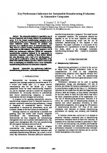
For analyzing trade-offs in cache designs occupying a constant area, it is useful to measure the cache utilization (the fraction of total cache area used to store data). The remaining area per block, called the block overhead, is largely occupied by the address tags, but also includes replacement information, validity bits, and buffer circuitry. For the 280,000 microprocessor, the cache holds 16 blocks in an area of 5.16 sq mm. Each block contains 16 data bytes, 8 data validity bits, 4 bits of replacement information ordering the blocks by their recency of use, a 28-bit address tag, and a tag validity bit. The address tag and its validity bit are 28.2 percent of the total area, the replacement information is 19.1 percent, and the data validity bits are 3.1 percent. Thus, the cache utilization is the remaining area used for data, or 49.6 percent. The block overhead, represented here by the symbol U , is measured in units of area occupied by a single data bit. (See accompanying box on block overhead.) The graph in Figure 3 shows the variation of cache utilization with block size for several values of block overhead. With no block overhead ( U = 0 units) the entire cache is used for data, so the utilization is always 1. The other values of block overhead roughly correspond to a 32-bit address tag where a tag bit and a data bit are equal in size (U = 32 units); a 32-bit address tag where a tag bit is twice the size of a data bit (U = 64 units); and a reasonable limit on the overhead, including replacement and validity bits (U = 128 units). For the 280,000 microprocessor cache, the block overhead is 130 units.
Table 1 shows how the number of data bytes stored in a cache varies with the block size and block overhead. The total bit areaequivalent for the cache is 8,192 data bits, corresponding to 1,024 data bytes with no block overhead. For fair comparison, we rounded the number of data bytes shown in the table to the nearest whole number based on the cache utilization formula as shown. Of course, an actual cache would contain an integral number of blocks. The table shows that the amount of data in the cache varies dramatically with the block overhead for block sizes less than 16 bytes and varies less for larger block sizes. For example, with a 64-unit block overhead, the number of data bytes in the cache approximately doubles when the block size increases from 4 to 16 bytes. To extend the concept of cache utilization just presented into a model for comparing cache designs with constant area, we made two assumptions: The area of a data bit remains unchanged as the block size varies. The block overhead remains unchanged as the block size varies. In practice these assumptions are only roughly accurate, so the cache utilization model provides useful insight but is not the basis for a design methodology. The first assumption is inaccurate because in a practical design the area of the various storage cells is adjusted to fine-tune speed and power requirements. Unfortunately, the trade-offs between layout geometry and circuit performance cannot be analytically modeled. The second assumption is inaccurate because the number of address tag and validity bits varies with the block size. In addition, the number of replacement bits can vary with the number of blocks. In fact, the latter sources of inaccuracy are not so troublesome: The number of tag bits only changes by one for every factor-of-two difference in block size, and in some designs the area for the tags may not change at all. For example, the Z80,OOO microprocessor cache stores its 28 address tag bits along a 32-bit bus connecting other functional units; the area in the four remaining bit positions is unused except for the tag validity bit. The area of the address tag is typically much greater than the sum of validity and replacement bits. Consequently, changing the number of validity and replacement bits has only a small effect on the block overhead.
Cache simulation and address traces To compare the performance of caches with constant area and varying block size, we developed a trace of address references and used it to simulate the action of the caches. Trace-driven simulation is a standard method for evaluating memory hierarchies. Using a trace permits simulation of caches with many strategies and parameter values in reproducible experiments.
I
Table 1. Quantity of data storage.
Block size (bytes)
Block Overhead (units) = v 0 32 64 128
I
2 4
8 16 32 64
Cache storage available (bytes) 1,024 341 205 114 1,024 512 341 205 1,024 683 512 341 1,024 819 683 512 1,024 910 819 683 1,024 964 910 819
We gathered the address trace used in this study by using an instruction-set simulator for the Zilog 28002 microprocessor.9 We initially made traces of 15 application programs written in C that execute in user mode under Zilog’s Zeus version of the Unix operating system. The traces contained records of the logical address for every instruction fetch (including immediate mode operand fetches), data fetch, and data store operation performed by the program. The traces also contained records for the system calls. Each address record indicated a 16-bit word referred to by the processor. After preliminary simulations using all test programs, we selected five typical traces for use in the study. The five programs had the following functions: compiler preprocessor, compare files, list a directory, sort a file, and edit a file. We developed a composite trace by selecting 25,000 consecutive records from each of the programs in round-robin order for a total of 1,000,000 records. Each record in the composite trace was tagged to identify the program from which it was derived. Combining separate traces in this manner is an effective way to determine the typical cache performance for a work load of programs and to simulate multiprogramming. We switched the program traces every 25,000 records because this is the typical interval between context changes for a minicomputer executing an educational time-sharing work load. lo
Constant area caches We used the address trace described in the previous section to compare the performance of simulated caches that possessed equal areas but different block sizes. Several values of block overhead were used. The simulations assumed the caches were fully associative with a least recently used (LRU) replacement algoAugust 1988 41
Cache memories 0.5 Cache area (bits)
0.4
t
M = 2,048 o----O = 8,192 = 32,768
0 .-c mL
0. )
)
2
4
(a)
8
16 Block size (bytes)
32
2
64
4
(b)
8
16 Block size (bytes)
32
64
n.
17c
.I 5 0.41
"'k
I
0.6
\
o,2k\\
0.1
2
(c)
4
8
16 Block size (bytes)
32
0.0
64 (d)
2
4
8
16
32
f
Block size (bytes)
Figure 4. Miss ratios for constant area caches when block overhead is 0 units (a), 32 units (b), 64 units (c), and 128 units (d).
rithm. We selected the LRU algorithm as it generally provides the best overall cache performance. Note that the selection of a replacement algorithm generally represents a secondary effect on cache performance. We used only the instruction and data fetch references in the simulation. We eliminated the data store references because cache design policies for write misses (write allocate or no write allocate) and memory update (write through or write back) are unrelated to the purpose of the study. In addition, the frequency of stores is small enough (7.5 percent) that their elimination does not affect the results of interest. (Also, for the common 48 IEEE MICRO
strategy of write through with no write allocate, the references made to memory are independent of whether writes hit or miss in the cache. Consequently, the cache's miss ratio for write references is not a very significant performance measure for such organizations.) During simulation, the cache was flushed at every system call. Although it would be preferable to flush only the fraction of the cache replaced by each particular type of system call, the information necessary to do so was unavailable. Shustek provides a description of how to gather the information when a working system is available.
Figure 4 shows the variation of miss ratio with block size for simulated caches with total areas of 2,048, 8,192, and 32,768 data bits. When the block overhead is 0 units, the caches store 256, 1,024, and 4,096 bytes of data regardless of the block size. For the other values of block overhead, if the number of blocks filling the cache area is not a whole number, we used linear interpolation to estimate the miss ratio. Figure 5 shows the traffic ratio for the simulated caches. We made three observations. First, the miss ratio becomes more sensitive to variations in block size as the block overhead increases. Thus, the graphs for small block overhead values appear relatively flatter than those for large block overhead values. Second, for large block overhead the miss ratio decreases rapidly with increasing block size. This process results when data continues to be stored in the cache as the block size increases, particularly in the case
of small block size and large block overhead. For example, when the block overhead is 0 units and the cache area is 8,192 bits, if the block size increases from 2 to 16 bytes, then the miss ratio is reduced by a factor of 3.8. But, if the block size is similarly varied for the same cache area and block overhead is 64 units, then the miss ratio is reduced by a factor of 6.5. Third, although the miss ratio generally decreases with increasing block size, the decrease is not sufficient to prevent an increase in traffic ratio. For instance, the traffic ratio increases by 23 percent when the block overhead is 64 units and the block size is varied from 2 to 16 bytes as previously described. The increase in traffic ratio indicates that off-chip memory bandwidth can be a significant performance limitation for a microprocessor containing an integrated cache with large block size. (Notice, however, that for the smallest simulated cache sizes, the miss ratio as well as the traffic ratio may
n
4.0 Cache area (bits)
3.0
3.0 =
32,768
.E2.0 E
.;2.0
.-
0 ._
L
0
c
. C I -
Pl.0
.o‘
2
0 4
8
16
32
64
Block size (bytes)
(a)
2
4
8
16
32
64
32
64
Block size (bytes)
(b)
3.0
02.0 c
0
E E l .o n v
.o (c)
2
4
8
16 Block size (bytes) ~~~
32
.o
64
2
c> 4
n ”
h
v
8
16
Block size (bytes)
(d) ~~~
~
figure 5. Traffic ratios for constant area caches when block overhead is 0 units (a), 32 units (b), 64 units (e), and 128 units (d). August 1988 49
Cache memories
A /nqbtcnes
I
Yes
No
Replace a cache block's address tag
Clear data validity bits
unit. The number of bytes in a transfer unit is called the transfer size; as before, the number of bytes associated with an address tag is called the block size. The strategy of fetching only a portion of a block is better for a given area and transfer size if the cache design has a lower miss ratio than a similar design with equal block and transfer sizes. We introduce some notation to present these concepts more clearly and formally. For a cache with block overhead U, cache area A , block size b, and transfer size t , the miss ratio is represented by m u (A,b,t). The relative miss ratio, represented by a,, is defined by the formula
I ' validity bit set?
Yes
I
Fetch transfer unit to
Set data validity bit
Thus, a, compares the miss ratios for a cache that combines several transfer units into a common block and a cache that has a single transfer unit per block. It follows from this observation: When combining several transfer units into a common block is a favorable strategy, the value of a ,is less than 1. When the transfer size is smaller than the block size, determining whether a reference hits in the cache involves two steps, as shown in Figure 6. Initially, the address tags are examined to determine whether the addressed block is in the cache (a block hit) or not (a block miss). For a block hit, the data validity bits are examined to determine whether the addressed transfer unit is in the cache block (a transfer unit hit) or not (a transfer unit miss). When a transfer unit hit occurs on a fetch, the data referred to is read from the cache. When a transfer unit miss occurs, the missing unit is read from main memory and stored into its location in the selected block. Then the corresponding data validity bit is set. When a block miss occurs, one of the cache blocks is selected for replacement, and the address of the missing block is stored in the selected block's tag. All of the data validity bits in the block are cleared. Then the addressed transfer unit is fetched and stored in the block, and the corresponding data validity bit is set. The IBM System/360, Model 85 uses a similar ~ t r a t e g y .The ~ cache associates 1,024 data bytes with an address tag, and transfers 64 bytes on a miss. (In IBM design terminology a group of 64 bytes is called a block, and a group of 1,024 bytes is called a sector.) B. Rau reported that IBM selected this organization to permit fully associative tag comparison at reasonable cost even before set-associative organization was known to be effective. l 2 For cache designs containing a given quantity of data storage and using a stack replacement algorithm, the strategy of transferring partial blocks always results in a relative miss ratio of 1 or greater. (In a stack replacement algorithm, the contents of a buffer are a subset of a larger buffer's contents at all times and for all traces when the buffers are initially empty.I3 An LRU
1 Address cache data
Figure 6. Flowchart for access to cache with multiple transfer units per block.
rise as the block size increases from 32 to 64 bytes. This occurs because with a block size comparable to the cache size, it becomes likely that useful information is replaced on a miss.) These three observations suggest the wisdom of maintaining a large block size but fetching only a portion of a block when a miss occurs. This strategy may keep the miss ratio low because large blocks result in good cache utilization, yet still keep the traffic ratio low. The following section considers such a strategy.
Transfer size and block size Most cache designs transfer an entire block when a cache miss occurs (an unsectored cache). Our simulation results indicate that fetching only a portion of the missing block may be a better strategy for integrated microprocessor caches (a sectored cache). The portion of a missing block that is fetched is called a transfer 50 IEEE MICRO
replacement is a stack algorithm; FIFO replacement is not.) To demonstrate the relative miss ratio, consider that at some time the transfer unit addresses ( t i ) that have been referred to are ordered in a stack. A cache with n blocks that each store one transfer unit contains the set of transfer units {to,tl, . . . , t n - l } If . instead each block stored k transfer units (kis a factor of n), a cache that contained the same quantity of data as before would include only n/k blocks. Figure 7 shows the contents of the two caches for each of the two strategies.At any time, the second cache contains a subset of the set of transfer units in the first cache-just those transfer units included in the first bnlk blocks on the stackwhile the contents of other transfer units are invalid. Only when the entire set of transfer units {to $1 ,...,t, -1 1 is contained in bnlkblocks does the second cache hold all the information in the first. Consequently, for any trace, the number of misses by the second cache must be at least the number of misses by the first cache, and the relative miss ratio is at least 1. For example, let’s assume a 16-byte cache size, a 4-byte transfer size, an LRU replacement algorithm, and four references to byte addresses 0, 100,0, and 100. With a 4-byte block size (Figure 7a with n = 4), a reference to byte 0 creates a miss, as does the next reference, to byte 100. The subsequent two references to bytes 0 and 100 are hits to blocks that already reside in cache. For a Idbyte block size (Figure 7b with k = 4 and one block, n = k), reference to byte 0 creates a miss that loads bytes 0 through 3 into the cache. Reference to byte 100 creates a new miss since its contents are not in the cache. Again, each subsequent reference to 0 and 100 causes a miss. An initially empty cache with a 4-byte block size has two misses, whereas a cache with a Idbyte block size has four misses. On the other hand, both caches have equal numbers of misses (two) for references to addresses 0, 12, 0, and 12. This reasoning applies when one compares cache designs with equal quantities of data, rather than equal areas. We used the address trace previously described to compare the performance of simulated caches with equal areas and equal transfer sizes, but different block sizes. As previously shown, the simulated caches were fully associative, with LRU replacement, and only the fetch references were used. Again, we used linear interpolation to estimate the miss ratio when the number of blocks filling the cache area is not a whole number. We performed simulations for caches with areas of 2,048, 4,096, 8,192, 16,384, and 32,768 data bits. The transfer size was varied from 2 to 16 bytes, the block size was varied from 2 to 64 bytes, and the block overhead was varied from 0 to 128 units. Table 2 summarizes the large number of simulation results. It shows the relative miss ratio for the indicated block and transfer sizes averaged over the simulated cache areas. Thus, the reported numbers (averaged over five programs) are calculated according to the formula for mean relative miss ratio:
(b)
bd bl
to,o invalid
b2
t2,o
tl,2 t2,i
ttn/k-l,l
I
t0,k-l t1,k-1
.. .
invalid I
I
I
bn/k-1
. ..
invalid
tn/k-1,2 ~
I
*
*
e
] ~
tn/k-1,k-1 ~~
Figure 7. Comparison of cache contents for two strategies single transfer unit per block (a), and multiple transfer units per block (b).
Table 2. Effects of transfer size and block size on miss ratios.
August 1988 5 1
Cache memories -1 z-a v ( 2 l w i b,, t )
q b ,t)E
5
i=l
When the block overhead equals 0, the quantity of data storage does not vary with block size. As demonstrated, Table 2 shows the miss ratio for a given transfer size with a block overhead of 0 is consistently worse when partial blocks are fetched. For instance, if the transfer size is 4 bytes, the number of misses is 43 percent greater when the block size is 32 bytes than when the block size is 4 bytes. But, for large values of block overhead the miss ratio can be improved by making the block size larger than the transfer size. This effect is most visible for small values of transfer size and large values of block overhead. For example, if the block overhead is 128 units and the transfer size is 4 bytes, the miss ratio decreases by 27 percent when the block size is raised from 4 to 16 bytes. The results indicate that a 2-byte block size should not be used, even when the data path to memory is only 2 bytes. When the transfer size is 2 bytes and the block overhead is as low as 32 units, the miss ratio can be improved more than 15 percent by increasing the block size from 2 to 8 or 16 bytes. For block overhead between 64 and 128 units, a block size of 16 bytes consistently provides good performance for transfer sizes between 2 and 16 bytes. One can best see the impact of Table 2 on practical design issues by plotting this data for selected block and
1.81
transfer sizes. Figures 8 and 9 show the relative miss ratio (the same as relative traffic ratio for this data) for sectored caches with constant transfer sizes of 4 and 8 bytes as a function of block overhead. The miss ratio is computed relative to an unsectored cache (Figure 7a). For a block overhead of 0 units and a transfer of 4 bytes (t = 4), Figure 8 indicates the extra traffic for sectored caches. Acache with a 64-byte block size has a 73 percent higher miss ratio (and a higher traffic ratio) than the reference cache organization (4-byte block size, 4-byte transfer unit). As the block overhead increases, sectoring becomes increasingly attractive, with larger blocks (b = 16) overtaking (b = 8) by a block overhead of 64 units. Indeed, by the time the block overhead reaches 128 units, the (b = 8) configuration, (b = 32), and (b = 16) are almost equally attractive. For .wider transfer units (t = 8 bytes, see Figure 9), the same tendencies are present, but the advantages of sectoring are not as pronounced, becoming significant only at a block overhead of 128 units. While the transfer unit of 2 bytes is not plotted, Table 2 shows that it closely resembles the situation of t = 4 in Figure 8. Table 1 provides the reason for the increasing advantage of sectoring as block overhead increases. As the overhead increases, fewer bits are available for data storage (the sum of cache directory and cache data storage). By sectoring the cache the directory is decreased, allowing more area for cache storage by increasing the available cache size.
I
I
Block size (bytes) 0 = 4 0 = 8
1.6
0.6
0=16 *=32
0 = 6 4
1.8 Block size (bytes)
’
0
I
32
I
64 Block overhead units
0.8 128
Figure 8. Miss rate relative to an unsectored cache with Cbyte block size and transfer widths. 52 IEEE MICRO
I 0
I
32
I
64
128
Block overhead units Figure 9. Miss rate relative to an unsectored cache with &byte block size and transfer widths.
Related research
References
Several other researchers have considered similar organizations for reducing the overhead of storing address tags in microprocessor cache memories. James Goodman observed both the disadvantage of transferring large blocks for small caches and the large cost of address tags for small blocks. l 4 He reported favorable results for simulated caches with differing block and transfer sizes, but did not model the block overhead quantitatively. (Goodman used the terms address block and transfer block where block and transfer unit are used here.) Hill and Smith simulated cache designs using a model similar to the cache utilization model presented here, but developed it independently. l5 They assumed that the tag and address bits are equal in area, as they are in the reduced instruction-set cache design with which they were familiar. They accounted for changes in the address tag’s size with variation of the block size, but ignored replacement information and other block overhead. Based on their simulation results, Hill and Smith also recommend combining several transfer units into a single block for microprocessor designs. (Hill and Smith use the terms block and subblock in their study.) Several microprocessors implement the strategy of fetching a partial block on a cache miss. In the 280,000 microprocessor cache, which has a block overhead of 130 units, the transfer size is either 2 or 4 bytes and the block size is 16 bytes. In general, the 280,000fetches a single transfer unit for a cache miss. Only when the memory system supports a burst of several data transfers in a single bus transaction does the processor fetch an entire cache block, and then only for instruction fetch misses. In DEC’s MicroVAX chip set, eight integrated circuits implement the complete VAX architecture. l6 One circuit contains the cache’s control logic and address tag array; the cache’s data is stored in standard memory components. Each tag is associated with four 16-byte transfer units to reduce the area dedicated to address tags.
1. M. Horowitz et al., “A 32-bit Microprocessor with Onchip 2KB Instruction Cache,” ISSCC 87 Digest of Papers, 1987, p. 30.
W
e have examined design trade-offs for integrated
microprocessor caches. We introduced a model of cache utilization to evaluate the effects on cache performance of varying the block size. By considering the overhead cost of storing address tags and replacement information along with data, we found that large block sizes lead to more cost-effective cache designs than predicted by previous studies. When the overhead cost is high, caches that fetch only partial blocks on a miss perform better than similar caches that fetch entire blocks. More generally, this study indicates that lessons from mainframe and minicomputer design practice should be critically examined to benefit the design of microprocessors.
2. D. Archer et al., “A 32-bit CMOS Microprocessor with On-chip Instruction, Data Caching and Memory Management,” ISSCC 87Digest of Papers, 1987, p. 32. 3. A. Rrenbaum, “A Pipelined 32-bit Microprocessor with 13KB of Cache Memory,” ISSCC 87 Digest of Papers, 1987, p. 34. 4. J.S. Lipstay, “Structural Aspects of the System/360 Model 85, Part 11: The Cache,” IBMSystems J., Vol. 7, NO.1, 1%8, pp. 15-21. 5. K.R. Kaplan and R.O. Winder, “Cache-based Computer
Systems,” Computer, Vol. 6, No. 3, 1973, pp. 30-36. 6. W.D. Strecker, “Cache Memories for PDP-11 Family Computers,” Proc. 3rd Ann. Symp. Computer Architecture, Jan. 1976, pp. 155-158. 7. J.C. Mudge, “Design Decisions for the PDP-11/60 Midrange Minicomputer,” Computer Engineering, Digital Press, Maynard, Mass., 1978. 8. A.J. Smith, “Cache Memories,” Computing Surveys, Vol. 14, NO.3, 1982, pp. 473-530. 9. Components Data Book, Zilog, Inc., Santa Clara, Calif., 1983. 10. M. Satyanarayananand D. Bhandarkar, “Design Tradeoffs in VAX-11 Translation Buffer Organization,” Computer, Vol. 14, No. 12, 1981, pp. 103-111. 11. L.J. Shustek, “Analysis and Performance of Computer Instruction Sets,” SLAC Report 205, Stanford Linear Accelerator Center, Stanford University, Stanford, Calif., May 1978. 12. B.R. Rau, Program Behavior and the Performance of Memory Systems, doctoral dissertation, Stanford University, 1977. 13. R.L. Mattson et al., “Evaluation Techniques for Storage Hierarchies,” IBM Systems J., Vol. 9, No. 2, 1970, pp. 78-117. 14. J.R. Goodman, “Using Cache Memory to Reduce Processor-Memory Traffic,” Proc. 10th Ann. Symp. Computer Architecture, June 1983, pp. 124-131. 15. M.D. Hill and A.J. Smith, “Experimental Evaluation of On-chip Microprocessor Cache Memories,” Proc. 1Ith Ann. Symp. Computer Architecture, June 1984. 16. W.N. Johnson, “A Very Large Scale Integration Superminicomputer CPU,” ISSCC Digest of Tech. Papers, 1984, pp. 174-175. August 1988 53
-
Cache memories
Donald B. Alpert is architecture group manager at National Semiconductor’s VLSI design center in Herzliya, Israel. His professional interests include computer architecture, microprocessor design, and memory hierarchy organization. He received the BSEE from Massachusetts Institute of Technology and the MSEE and PhD degrees from Stanford University.
Michael J. Flynn is a professor of electrical engineering at Stanford University. His experience includes 10 years at IBM working in computer organization and design. He has also been a faculty member at Northwestern and Johns Hopkins Universities and was the director of Stanford’s Computer Systems Laboratory from 1977 to 1983. His current interests include computer organization and computer architecture. Flynn has served as vice president of the Computer Society and was a founding chair of the Technical Committee on Computer Architecture, as well as ACM’s Special Interest Group on Computer Architecture.
Questions about this article can be directed to Michael Flynn at the Computer SystemsLaboratory, Stanford University, Stanford, CA 94305-4055.
Reader Interest Survey Indicate your interest in this article by circling the appropriate number on the Reader Interest Card. Low 159
Medium
160
High
161
Have you heard about our...
Technical Committee on Multiple-Valued Logic? For information on this, or any of our 32 other TCs, members* may contact THE COMPUTER SOCIETY 10662 Los Vaqueros Circle Los Alamitos, CA 90720 Telephone: (714) 821-8380
Nonmembers: Join us. For membership information, circle number 202 on the reader service card. 54 IEEE MICRO