was supported in part by the AFOSR under Dr. Howard Schlossberg, in part by the NCIPT, and in part by the DOD SBIR under Contract DAAH01-97-. C-R026.
IEEE PHOTONICS TECHNOLOGY LETTERS, VOL. 10, NO. 2, FEBRUARY 1998
267
Phased-Array Optically Controlled Receiver Using a Serial Feed Boris Tsap, Yian Chang, Harold R. Fetterman, Fellow, IEEE, A. F. J. Levi, David A. Cohen, and Irwin Newberg, Member, IEEE
Abstract—Extension of a new optically controlled serially fed phased-array system to the receive mode of operation has been demonstrated. Our system uses the pulsed nature of microwave radars in a manner similar to clocked systems used in digital configurations. This novel approach requires only the use of one tunable laser, one optical modulator, and one chirped fiber grating unit. In this letter, we present an experimental demonstration of a two-element serially fed wide frequency range receiver that validates the feasibility of this novel concept. Our system can be readily expanded with multiple elements and transmit/receive modules for a complete phased array system. Index Terms—Directional communications, fiber gratings, optical control, optical fiber delay line, phased-array radar.
I. INTRODUCTION
W
E HAVE recently reported the development of a novel optically controlled phase array transmit configuration, suitable for numerous applications, including phased array radar and directional data communications [1]–[3]. The serialfeed concept used in these systems represented a departure from conventional parallel-feed approaches, which are very laser intensive [4]–[14]. Our system’s use of a single wavelength tunable laser, one modulator, and one fiber grating time delay element provided a major simplification in the number of required optical components. In this letter, we report the demonstration of the receive portion of this concept using a two-element receiver with observation directions ranging from 30 to 30 . The dependence on one time delay unit to provide time/phase shifts for all of the antenna elements distinguishes this serially-fed system from previously implemented receive systems [13], [15]. Our introduction of a chirped fiber grating to the system enhances its capability by making its directional operation continuously variable. Combined with our transmit capability [1], and with the use of a T/R switch, this new design can now be extended to a complete transmit/receive radar system. Manuscript received June 30, 1997; revised October 17, 1997. This work was supported in part by the AFOSR under Dr. Howard Schlossberg, in part by the NCIPT, and in part by the DOD SBIR under Contract DAAH01-97C-R026. B. Tsap is with Pacific Wave Industries, Inc., Los Angeles, CA 90024 USA. Y. Chang and H. R. Fetterman are with the Department of Electrical Engineering, University of California at Los Angeles, Los Angeles, CA 90095 USA. A. F. J. Levi and D. A. Cohen are with the Department of Electrical Engineering, University of Southern California, Los Angeles, CA 90089-1111 USA. I. Newberg is with the Radar and Communication Systems, Hughes Aircraft Company, Los Angeles, CA 90009-2426 USA. Publisher Item Identifier S 1041-1135(98)01269-5.
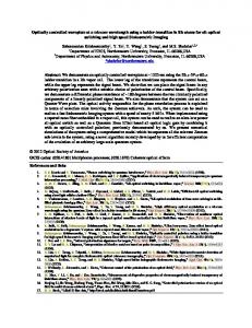
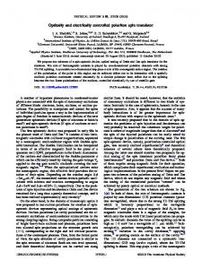
Fig. 1. Basic serially fed receive mode configuration for an array of n elements. A chirped fiber grating in conjunction with a tunable laser provides the necessary phased delays for virtually continuous directional operation. A second tapped delay line in parallel can be added to achieve almost continuous temporal operation.
II. SERIALLY FED RECEIVER CONFIGURATION The serially fed receiver consists of a timing unit and a serial to parallel conversion distribution network as shown in Fig. 1. The timing unit sequentially generates delays designated for a given direction of observation. The distribution network then transforms these delays into parallel signals and feeds them to the antenna elements. In the basic receive configuration (Fig. 1), the train of -long laser light pulses, where is the tapped fiber is speed of light in fiber, is modulated delay length and at the desired microwave frequency, and directed through an optical circulator to a fiber grating. By reflecting from a particular point on the fiber grating a wavelength-selected phase shift is imposed onto each modulated optical pulse. The returned light from the third port of the circulator enters the distribution network which supplies each mixer with the local oscillator (LO) signal for mixing with the received microwave signal. Assume that the tapped delay line is loaded sequentially pulses from a tunable laser each carrying the LO with respectively, signals that are phase shifted by to the mixers. The tunable laser must switch wavelengths on and therefore has little effect on typical the order of a radar signals which have durations of hundreds, and even thousands, of nanoseconds. At the beginning of the receive mode of operation, the first pulse supplies the last mixer and in the th pulse supplies the first mixer. After an interval
1041–1135/98$10.00 1998 IEEE
268
IEEE PHOTONICS TECHNOLOGY LETTERS, VOL. 10, NO. 2, FEBRUARY 1998
considered unknown, quadrature mixers were used to provide homodyne IF signals in two quadrants. The two outputs of the mixer associated with the first antenna element contain dc components given by
For the outputs of the mixer associated with the second antenna element, we have
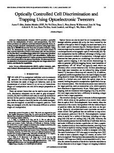
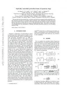
Fig. 2. Target scanning with the receiver pointed to six different “listening” directions, defined by the tunable laser wavelength �t . In this demonstration, experimentally determined “listening” directions correspond to the angles 0 and S 0 > 0. where S
=
time, the second pulse will reach the th mixer and become its LO signal carrier. At the same time, the th pulse will be supplying the first mixer and the cycle continued. Note that the receiver continues to “listen” in the same direction after each wavelength progression because only the relative phases between mixers (differential phase are important. This wavelength progression repeats until the last loaded pulse reaches the first mixer. At this point, there would be a loss of duty cycle for the simplest configuration while the line is reloaded. However, in order to achieve almost continuous operation, our design can incorporate the option of a second tapped delay line with an extra delay length which can be switched to feed each mixer the appropriate phase. Although, as in our initial transmit experiment a two-laser switch system was used, we have utilized a linearly chirped grating, which along with a tunable DBR laser will provide almost continuous scanning for the ultimate system. III. EXPERIMENT In an experimental demonstration with a two-element array, we used two external cavity wavelength tunable lasers in conjunction with two optical modulators to simulate a single fast tunable laser. The wavelength of the first laser was fixed at and the wavelength of the second laser was tuned to different values to control the “listening” direction of the receiver. A continuously chirped fiber grating centered at 1310 nm with a 10-nm bandwidth ( 97% reflectivity) was used as the wavelength sensitive element. Phase delayed and were signals corresponding to the reflections of generated by the basic true time delay (TTD) timing unit used in the transmit configuration and, therefore, yielded squint-free operation. An RF signal was simultaneously fed to a transmitting horn placed on a rotating stage to simulate the signal returned from a target. The RF signal picked up by each of the receiving antenna elements was fed to the RF port of a mixer. The LO input of the mixer at each element was provided with the phase delayed signal from the timing unit and photodiode. Because the target distance was
where and are proportional to the LO amplitudes sent and are proportional to the received to the mixers, RF amplitudes, is an unknown phase in the received RF signals due to the unknown target distance, is the phase difference between the LO signals (from the timing is the phase difference between the unit), received RF signals due to the different path lengths from the target, is the target angle, and is the spacing between the antenna elements. The four outputs of the mixers were fed to a computer for processing. The computer calculated the final result in the form (1) The phase difference between the LO signals is set in the timing unit by the fiber grating for each wavelength pair and is described by
where is a parameter involving the chirp of the fiber grating. For a given target direction, can be extracted by plotting for different . The calculated function in (1) is zeroed, with a positive slope, when . Therefore, the target angle can be written as (2) In this feasibility demonstration, the receiver had only two elements and to increase the resolution of the system, we had chosen to use the function in (1) to determine the target angle because of its sensitivity near . To demonstrate the ability of the system as a phased array radar receiver, we chose six different wavelength pairs to deliver the LO signals; effectively, the receiver was used to “listen” to six different directions. For a selected direction (wavelength pair), the target angle was changed from 30 to 30 with a step size of 1 . As shown above at the right “listening” direction the function is zero with a positive slope. In these experiments, the RF frequency was set to was kept at 1310.6 nm and was tuned to 8 GHz, six different wavelengths. Fig. 2 shows the corresponding function versus the target angle for each wavelength pair. The least square best-fit functions were calculated and used to determine the target directions with higher accuracy. The measured target angles (corresponding to the angles where 0 and 0 in Fig. 2) are 17.7 , 11.6 , 2.4 , 10.4 , 19.4 , and 27.4 . The theoretically calculated six “listening” directions, using (2), are 19.3 , 12.8 , 0 , 12.8 , 19.3 , and 26.2 . The measured values are well within the expected 3 of the two antenna element theoretical values.
TSAP et al.: PHASED-ARRAY OPTICALLY CONTROLLED RECEIVER USING A SERIAL FEED
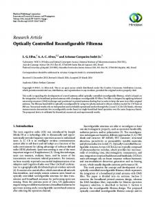
Fig. 3. Wavelength scanning with the target located at 0� and the fixed 1310.55 nm. Using a best-fit function to the function, wavelength �f the experimentally determined target direction is � 0.6� .
=
=
sine
In another experimental modality to demonstrate the capability of changing the “listening” direction continuously, the target angle was fixed at 0 and was set to 1310.6 nm. The wavelength was then scanned from 1306.0 to 1315.5 nm with a step size of 0.1 nm determined by the resolution of the tunable laser. The function versus the wavelength is shown in Fig. 3. The solid line is the best-fit -function that has a zero value (with a positive slope) at the wavelength 1310.60 nm corresponding to 0.6 according to (2). The results show excellent agreement with predictions and indicate that the serial system works well in the receive mode. IV. CONCLUSION We have successfully demonstrated a receive mode operation of a serially fed optically controlled phased array system. It uses the same basic elements as the previously reported transmitter and completes the serial system. For a practical system with multiple elements, the mixer outputs would be processed in the following way: (3) When the signal arrives in from the desired direction, the angular phase dependency is removed by mixing with the is selected LO signals for that direction; the scalar function maximized by this process. In a radar application, this scalar signal can then be used to determine the target distance. In a practical multiple-element radar system, the beam width will be much narrower than that of our two-element array. Therefore, the function in (3) can be used to sum the mixer outputs together for further processing. will be maximized as a sharp peak only at the selected direction because the mixer outputs are “in phase” at this receive angle and “out of phase” elsewhere. In a pulsed transmit/receive radar system, once a RF pulse has been transmitted, the system has to switch to the receive mode to listen for the echo. The conjugate differential phase of that used in transmit is now used in the receive mode since the mixers generate a difference frequency and
269
subtract the phases of the two input signals to be used in forming the scalar quantity . This phase requirement can be achieved by using the fiber grating in the reverse direction or by using the transmit wavelengths in reverse order. This technique provides the wide frequency range squint-free receiver steering since real-time delays, generated in the fiber grating, are used to obtain the phase angles. The extension of the two-element serially fed optically controlled system to the receive mode has been presented. Of greater importance, however, is that it is now possible to implement the concept of a serial feed in a complete radar system, which will require a transmit/receive switch module and a dual feed line for a continuous operation. Finally, because of its simplicity and the significant reduction in the number of optical components, this system has major advantages over proposed conventional parallel configurations and is one of the few which have actually been demonstrated [13], [15]. REFERENCES [1] Y. Chang, B. Tsap, H. R. Fetterman, D. A. Cohen, A. F. J. Levi, and I. Newberg, “Optically controlled serially fed phased-array transmitter,” IEEE Microwave Guided Wave Lett., vol. 7, pp. 69–71, Mar. 1997. [2] D. A. Cohen, Y. Chang, A. F. J. Levi, H. R. Fetterman, and I. Newberg, “Optically controlled serially fed phased array sensor,” IEEE Photon. Technol. Lett., vol. 8, pp. 1683–1685, Dec. 1996. [3] D. A. Cohen, A. F. J. Levi, Y. Chang, H. R. Fetterman et al., “Video broadcast using an optically controlled serially-fed phased-array antenna,” in Proc. SPIE, 1996, vol. 2844, pp. 258–268. [4] D. Dolfi, P. Joffre, J. Antoine, J.-P. Huignard, D. Philippet, and P. Granger, “Experimental demonstration of a phased-array antenna optically controlled with phase and time delays,” Appl. Opt., vol. 35, no. 26, pp. 5293–5300, 1996. [5] D. Dolfi, P. Joffre, J. Antoine, J.-P. Huignard, D. Philippet, P. Granger, and J. Chazelas, “Photonics for phased array radars,” in Proc. SPIE, 1995, vol. 2560, pp. 158–165. [6] H. R. Fetterman, Y. Chang, D. C. Scott, S. R. Forrest, F. M. Espiau, M. We, D. V. Plant, J. R. Kelly, A. Mather, W. H. Steier, R. M. Osgood, “Optically controlled phased array radar receiver using SLM switched real time delays,” IEEE Microwave Guided Wave Lett., vol. 5, pp. 414–416, Nov. 1995. [7] L. Xu, R. Taylor and S. R. Forrest, “True time-delay phased-array antenna feed system based on optical heterodyne techniques,” IEEE Photon. Technol. Lett., vol. 8, pp. 160–162, Jan. 1996. [8] R. D. Esman, M. Y. Frankel, J. L. Dexter, L. Goldberg, M. Parent, D. Stilwell, and D. Cooper, “Fiber-optic prism true time-delay antenna feed,” IEEE Photon. Technol. Lett., vol. 5, pp. 1347–1349, Nov. 1993. [9] A. Molony, C. Edge, and I. Bennion, “Fiber grating time delay element for phased array antennas,” Electron. Lett., vol. 31, no. 17, pp. 1485–1486, 1995. [10] N. A. Riza and N. Madamopoulos, “Phased-array antenna, maximumcompression, reversible photonic beam former with ternary designs and multiple wavelength,” Appl. Opt., vol. 36, no. 5, pp. 983–996, 1997. [11] D. T. K. Tong and M. C. Wu, “Programmable dispersion matrix using Bragg fiber grating for optically controlled phased array antennas,” Electron. Lett., vol. 32, no. 17, pp. 1532–1533, 1996. [12] W. D. Jemison, T. Yost, and P. R. Herczfeld, “Acoustooptically controlled true time delays: Experimental results,” IEEE Microwave Guided Wave Lett., vol. 6, pp. 283–2855, Aug. 1996. [13] J. J. Lee, R. Y. Loo, S. Livingstone, V. I. Jones, J. B. Lewis, H.-W. Yen, G. L. Tangonan, and M. Wechsberg, “Photonic wideband array antennas,” IEEE Trans. Antennas Propagat., vol. 43, pp. 966–982, Sept. 1995. [14] A. P. Goutzoulis, J. M. Zomp, B. K. Davies, and P. Hrycak, “Hardware compressive, true time-steering for control of phased array antennas,” Rome Lab. Rep., no. RL-TR-95-293, Jan. 1996. [15] M. Y. Frankel and R. D. Esman, “True time-delay fiber-optic control of an ultrawideband array transmitter/receiver with multibeam capability,” IEEE Trans. Microwave Theory Tech., vol. 43, pp. 2387–2394, Sept. 1995.