AbstractâThe paper presents a review on physics-based noise simulation techniques for RF semiconductor devices, starting with the small-signal case but with ...
IEEE TRANSACTIONS ON ELECTRON DEVICES, VOL. 50, NO. 3, MARCH 2003
633
Physics-Based Simulation Techniques for Smalland Large-Signal Device Noise Analysis in RF Applications Fabrizio Bonani, Senior Member, IEEE, Simona Donati Guerrieri, Member, IEEE, and Giovanni Ghione, Senior Member, IEEE
Invited Paper
Abstract—The paper presents a review on physics-based noise simulation techniques for RF semiconductor devices, starting with the small-signal case but with greater stress on noise in largesignal (quasi)-periodic operation. The nonautonomous (forced) operation case will be considered, which is relevant to all RF applications apart from oscillators. Besides their importance in device design, physics-based noise models can also suggest viable and correct strategies to implement circuit-oriented models, e.g., compact models. From this standpoint, the connection between physicsbased and circuit-oriented modeling will be discussed both in the small-signal and in the large-signal case, with particular stress on the treatment of colored noise in the large-signal periodic regime. Index Terms—Circuit modeling, circuit noise, semiconductor device modeling, semiconductor device noise.
I. INTRODUCTION
D
URING the last few years, dramatic progress has been made in CAD tools for the noise analysis of RF and microwave analog circuits. Noise simulation, formerly limited to linear circuits, was extended to the less widely understood largesignal regime, with direct application to analog RF subsystems such as mixers and frequency multipliers. However, progress in circuit simulation tools was not entirely paralleled in the development of device noise models, although the final result of the noise simulation is as good as the noise models implemented in the simulator. In many modeling areas involving noise operation, controversial points remain. A first example concerning the apparently well-established field of small-signal noise modeling is the quest for a satisfactory compact MOS noise model relating in a simple way the device noise performances to physical and technological parameters. In a sense, compact noise FET models could be bypassed Manuscript received May 24, 2002; revised October 1, 2002. This work was supported in part by the Center of Excellence on Multimedia Radiocommunications (CERCOM) of Politecnico di Torino and by the Italian Ministry of Research (MIUR) through the COFIN 2000 project, and of the “Progetto giovani ricercatori” of Politecnico di Torino. The review of this paper was arranged by Editor D. B. M. Klaassen. F. Bonani and G. Ghione are with the Dipartimento di Elettronica and INFM Unità Torino Politecnico, Politecnico di Torino, 10129 Torino, Italy. S. Donati Guerrieri is with the Dipartimento di Elettronica, Politecnico di Torino, 10129 Torino, Italy. Digital Object Identifier 10.1109/TED.2003.810477
in circuit design, since measurement-based, partly empirical approaches developed in the field of microwave FETs (see e.g., [1], [2]) have been proposed since the late seventies on the assumption that the short-channel FET physics is too complex to make a real, analytical compact model worth developing: such models have been successfully applied to MOSFETs, e.g., in [3]. On the other hand, although the search for predictive compact MOS noise models has led to a great deal of work in the RF community, in many circuit simulators the actual device models available are legacy ones, sometimes even hardly correct (e.g., only valid for long-channel devices [4]). A second example is a comparative lack of deep understanding of some of the device noise properties in the largesignal regime. Since the pioneering paper of Dragone [5], it has been more or less widely understood that fast noise mechanisms (i.e., those characterized by a white spectrum in small-signal operation) are modulated, in large-signal conditions, by the instantaneous working point. Such a modulation enables to extract, somewhat empirically, from the small-signal power spectrum the statistical information on the frequency-converted large-signal noise (i.e., the so-called sideband correlation matrix). Unfortunately, in many circuits the most important noise mechanisms are those leading, in small-signal operation, ) spectrum. Several approaches have to a colored (e.g., been proposed to model the frequency conversion of such slow fluctuations [6], [7], but a satisfactory solution has not been found yet. Thus, it is not well understood at present up to which extent an accurate large-signal noise device model can be extracted from information (also experimental) on small-signal noise. Physics-based numerical noise simulation can give, in the long term, a satisfactory answer to many noise modeling problems encountered in RF and microwave analog circuit design. First, a noise simulator based on the numerical solution of a transport model rather than on approximate analytical approaches makes available a direct link between the device technology and its noise behavior. This is particularly true in small-signal noise analysis, which can be performed independently of the embedding circuit so as to directly evaluate the device noise parameters as a function of frequency. However, physics-based noise analysis can also be exploited as a direct
0018-9383/03$17.00 © 2003 IEEE
634
way to test large-signal circuit-oriented noise models from the standpoint of structure and consistency, thus providing a manageable test set whereon virtual measurements can be readily made. The aim of the present paper is to provide a comprehensive review of physics-based noise simulation of RF and microwave devices both in the linear and nonlinear (large-signal) regime. The analysis will be confined to nonautonomous (i.e., forced) device operation, thus excluding from the treatment the oscillator case, which still is a matter of advanced research [8]. As in many other fields, also in noise simulation the whole development of the underlying physical theory was largely complete well before numerical noise simulations were attempted. Noise simulation in an engineering sense was perhaps founded by the paper of Shockley et al. of 1966 [9], which established as a viable analysis tool the so-called impedance field method, basically a Green’s function technique describing the device noise as the superposition of microscopic fluctuations properly propagated to the device terminals. The impedance field method and related techniques were widely exploited for the small-signal noise analysis of the most important classes of devices, above all bipolar, see, e.g., the papers by Van Vliet et al. [10]–[12]. Despite the several quasi-two-dimensional implementations of the IFM, the first full two-dimensional (2-D) physics-based numerical noise model was presented only in 1989 by Filicori and Ghione [13], [14] and was extended to the bipolar case by Bonani et al. [15], who also developed the first large-signal noise analysis in the quasi-periodic regime [16]. Small- and largesignal physics-based FET noise analyses based on the so-called active line quasi-2-D approach were successfully developed by the University of Lille (IEMN) group (see [17], [18] and references therein). Although the small-signal noise analysis has been recently implemented in a few commercial device simulators (e.g., Integrated Systems Engineering DESSIS [19], Avant! Corp. TaurusDevice [20]), large-signal noise simulation, which requires one to analyze the active device together with the embedding circuit, still is a matter of research: both time- and frequency-domain, namely Harmonic Balance, methods are in principle feasible, but up to now frequency-domain techniques only have been proposed due to their efficiency in device analysis and to the fact that they are a direct extension of the small-signal treatment. Moreover, it should be stressed that numerical noise analysis, already at the small-signal level, can show unexpected complexities in seemingly well-known cases; as an example, see the GR noise in short uniform samples [21] or the thermal noise in low-doping resistor (see [22, ch. 4]). While many of the phenomena numerical simulation can help in unveiling were already known, at least at a qualitative level, the availability of this new tool has greatly widened the opportunities for analysis and understanding of the noise behavior. This is even more true in large-signal noise analysis, where careful interpretation of the frequency conversion of slow fluctuations can also lead to a better insight into the possible structure of compact noise models. The paper is organized as follows. Section II is devoted to the circuit representation of noisy devices, both in small-signal and large-signal forced regime. In Section III the available ap-
IEEE TRANSACTIONS ON ELECTRON DEVICES, VOL. 50, NO. 3, MARCH 2003
proaches for physics-based noise analysis, again in linearity and for large-signal excitations, are briefly reviewed, with particular emphasis on frequency-domain Green’s function-based approaches. A discussion on the application of physics-based simulation to the development and validation of circuit-oriented noise models is developed in Section IV, again with a greater emphasis on the large signal case. Finally, conclusions are summarized in Section V. II. CIRCUIT REPRESENTATION OF NOISY DEVICES The occurrence of noise, in the form of fluctuations of the electrical variables at the terminals of any device, is an unavoidable feature strictly related to carrier transport in semiconductors. From a circuit perspective, the customary representation is based on the assumption that fluctuations cause a perturbation of the electrical device working point and that, therefore, noise can be interpreted as a small-amplitude random signal superimposed to the currents and voltages at the device ports. In other words, noise is represented as a set of impressed (voltage or current) electrical sources connected to the device terminals, namely the device noise generators, which are described through zero-average stochastic processes. Since, at a circuit level, the physically meaningful quantity is the noise power exchanged, the noise generators are usually characterized by their second-order statistical properties: these are sufficient to derive system-oriented parameters, such as the noise figure for a two-port device [22]. From a circuit standpoint, the representation of noise depends on device operation that also influences the statistical properties of the stochastic processes describing fluctuations. In this paper, we shall consider only the case of forced operation; this basically covers all of the main applications, with the important exclusion of autonomous systems, i.e., oscillators. We shall consider separately two cases: 1) the small-signal (SS) regime, occurring if the forcing term is made of the superposition of a continuous bias (DC) and of a small-amplitude time-varying term and 2) the large-signal, (quasi-)periodic (LS) regime, corresponding to a device excitation made of (quasi-)periodically time-varying signals. The steady-state working point in LS operation is again (quasi-)periodically time-varying, though the nonlinear behavior of the device (and of other nonlinear circuit elements, if any) results in the generation of frequency components at all of the linear combinations (with integer coefficients) of the input frequencies: such components will be denoted as harmonics.1 Once the noise generators have been characterized, they can be implemented into circuit simulators in order to perform system-level noise estimations: as a matter of fact, almost all commercial simulators now allow, either in the time or frequency domain, for noise analysis, in some cases both in SS and LS conditions. Representative examples are SPICE [23], [24], Agilent ADS (Advanced Design System) [25], Cadence Design Systems SpectreRF [26], AWR Microwave Office [27], and Avista Design Systems SP/XL-RF [28]. A recent review on circuit CAD tools for RF applications can be found in [29]. 1These correspond, for strictly periodic operation, to integer multiple frequencies of the fundamental, while in quasi-periodic conditions the intermodulation products are also taken into consideration.
BONANI et al.: PHYSICS-BASED SIMULATION TECHNIQUES
635
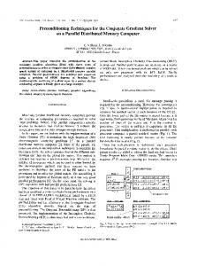
scribed by the vector of short circuit noise current generators, leading to the parallel description [see Fig. 1(b)] (1b) where
and (2)
Equation (2) shows that the series and parallel noise representations are equivalent and that
(a)
(3a) (3b)
(b) Fig. 1. Equivalent circuit of a noisy and (b) parallel representation.
N -port device in SS operation: (a) series
A. SS Operation In the simple case of SS operating regime, the -port device is represented as a linear -port whose port voltages and currents are the (small-change) variations of the corresponding total variables with respect to the dc working point. being the vector of open circuit noise voltage genWith erators at the ports, such stochastic processes are stationary [22] and therefore are completely characterized in the frequency ( domain by the corresponding correlation matrix is the angular frequency). This implicitly assumes that the linearized device can be represented by a small-signal impedance , thus leading to the series representation shown in matrix Fig. 1(a) as
where denotes Hermitian conjugation. From the standpoint of circuit simulations, noise analysis is a simple small-signal analysis which takes as inputs the noise generators, whose power and correlation spectra are assumed to be known as a function of frequency. The output is the correlation matrix for the equivalent noise generators at the outer ports of the whole circuit (see e.g., [31]): several techniques are available to perform such calculations [32], [33], which laid the basis for efficient numerical physics-based noise analysis [22]. Circuit oriented models can be exploited to describe the correlation spectra of the noise generators as a function of the device dc operating point: some of them have, to various degrees of approximation, a connection to the physical device structure (the so-called compact models, see, e.g., [34]), others are based on experimental results only, e.g., the Pospieszalski two-temperature model [1], originally devised for noise analysis of microwave FETs, and the so-called PRC model [2], [35]: see [36] for a comparison with reference to microwave FETs. In any case, linear RF applications mostly deal with white noise spectra (thermal and shot noise), while in low-frequency operation colored noise becomes important, in particular generation-recomnoise. Notice, however, that linear filbination (GR) and tering of white noise through circuit transfer functions can give a colored nature to the output noise generators, e.g., even for a low-pass filter the white thermal noise of the resissimple tance may result in colored fluctuations on the load. B. LS Operation
(1a) where the Fourier transformation of the time-domain signal is denoted as , and we have assumed to Fourier-transform even the noise generators, although this is a mathematically critical procedure [30] based on the hypothesis that the dc working point is a stable equilibrium of the dynamic model with respect to small variations. With the assumption that the linearized device admits an admittance matrix representation, noise can be equivalently de-
Operating the device under quasi-periodic large-signal conditions means that a periodic forcing signal is applied to at least one of the device ports, thus making quasi-periodic in time, in steady-state conditions, all of the device electrical (port voltages and currents) and physical (carrier densities and electric field) can be expanded in variables. This means that any variable Fourier series (4)
636
IEEE TRANSACTIONS ON ELECTRON DEVICES, VOL. 50, NO. 3, MARCH 2003
where are the harmonic (angular) frequencies2 and are the corresponding complex (harmonic) amplitudes, satisfying ( denotes complex conjugate). In practice, the Fourier series has to be truncated to a finite harmonic order , so that independent real numbers are required to characterize completely the truncated Fourier series [22], [16]. According to the usual assumption that noise is a small-change variation of the steady state, a linear perturbation analysis around the time-varying periodic working point (the so-called small-signal large-signal analysis [37]) can be carried out [22]. As a consequence, the linearized device (and circuit) becomes a linear periodically time-varying (LPTV) system [6]. From a circuit standpoint, the consequence of the LPTV nature of the linearized device is that the variations of the port voltages and currents with respect to the steady state can be expressed through a phasor-like analysis as [37], [16]
(a)
(5)
corresponds to the upper sideband of the where th harmonic, i.e., a frequency displaced by an amount from the th harmonic itself. A truncated representation has been al(see [37] for details). Notice ready used in (5), where that each port voltage and current is thus represented as a vector complex components, the various sideband amwith plitudes [22]. The linear relationship between the voltage and current variations is expressed through a conversion matrix [37] ( or ) that relates the sideband amplitudes, thus accounting for frequency conversion effects among the sidebands (see [16] for further details) (6)
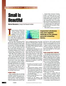
(b) Fig. 2. Equivalent circuit of a noisy two-port device in LS operation: (a) series and (b) parallel representation. The left part of the linear multifrequency representation is the sideband expansion of physical port 1, and the right part corresponds to physical port 2.
the series and parallel representations of a noisy device in LS operation as a linear, multifrequency multiport (7a)
In the previous equation, we have assumed that both the impedance and admittance representations are possible, and we have collected all of the port sideband amplitudes into a single for voltages and for currents), each having vector ( rows for an -port circuit. Concerning noise, the stochastic processes representing fluctuations, both at a circuit and microscopic level, are amplitude modulated by the time-varying noiseless working point, and therefore they are converted into cyclostationary processes [6], [16]: the most important feature is that, being nonstationary, such processes have correlated frequency components. Cyclostationarity implies that such correlation takes place only for those frequencies having the same distance from a harmonic of the noiseless steady state. The second order statistical properties are thus described through the so-called sideband correlation matrix (SCM) [16], [38] that represents the correlation and spectra between the various sidebands. By denoting as the sideband (stochastic) amplitudes of the noise generators, a formal generalization of (1) is easily derived, thus leading to 2In the simplest case of periodic operation, ! = k! where k is a positive integer and ! = 2�=T , T being the period of the excitation.
(7b) Notice that, in analogy with the remark in Section II-A, the and of the cyclostationary noise sideband amplitudes processes require mathematical care to be consistently defined: again, the basic assumption is the stability of the limit cycle corresponding to the time-varying noiseless operating point of the device. Fig. 2 shows the linear multifrequency equivalent circuit of a noisy two-port in LS operation. The relationship between the parallel and series representation is derived in full analogy with the SS case, leading to an expression formally identical to (3). Noise analysis in circuits driven in LS conditions received a great deal of attention for several decades because of its importance in RF applications; in particular, noise in mixers has been studied since the 1940s [39], [40], [41], and noise in switched capacitor networks has been analyzed, e.g., in [42], where a time-domain algorithm is presented. Only recently, however, general purpose CAD techniques in the frequency domain have been proposed for the analysis of large-scale circuits [38], [43]. An open research issue is the development of reliable compact device noise models in LS conditions (cyclostationary noise generators): a quite common assumption is based on the work by
BONANI et al.: PHYSICS-BASED SIMULATION TECHNIQUES
Dragone [5], who derived an expression for the LS noise spectra in a memoryless (resistive) one-port as a result of the instantaneous amplitude modulation of SS white noise spectra by the device time-varying working point, based on the hypothesis that fundamental fluctuations are due to scattering events faster than the electrical variable dynamics. Clearly, this assumption ceases to hold whenever the SS spectra are not white, e.g., for GR and noise: a general discussion of this can be found in [6]. III. PHYSICS-BASED NOISE ANALYSIS The aim of physics-based (PB) noise analysis is to evaluate the second-order statistical properties of the device noise generators (including their correlation) from the elementary, microscopic fluctuations (the microscopic noise sources) occurring within the device volume, given the noiseless working point of the device. The microscopic noise sources, assumed to be known from physical first principles, can be associated with three phenomena [44], [22]: fluctuations of the velocity of free carriers (leading to diffusion noise which, in thermal equilibrium, corresponds to thermal noise), fluctuations of the number noise. The latter of free carriers (leading to GR noise), and has been widely studied from an experimental standpoint due to its great importance in circuit applications, in particular for LS systems and oscillators where upconversion transfers part of the low-frequency noise to RF. Unfortunately, the physical noise is still an open issue; several competing theorigin of ories have been proposed [45], [46], but experimental verificanoise can tions have shown controversial results. Basically, be interpreted either as a superposition of surface or bulk GR noise spectra with a proper distribution of time constants or as the result of mobility fluctuations. Finally, a more fundamental, noise has been also proposed [46]. quantum origin of From a practical standpoint, diffusion noise is described, in SS conditions, by means of a white stochastic process [44], [22], resulting from fast microscopic intraband scattering processes. Also, the GR noise source, at least in a fundamental description [44], [21], can be described by a white process, although, in the literature, a colored Lorentzian source is often used [47]: in [21], the limits of applicability of the Lorentzian source are discussed, and it is pointed out that the white source only has general validity. Since the spectra of the microscopic diffusion and GR noise sources are white, assuming that the LS steady state is much slower then the microscopic intraband and interband scattering processes,3 the microscopic noise sources in LS operation are derived through instantaneous amplitude modulanoise tion of the SS ones, as discussed in [16]. The case of is much more involved: in fact, up to now no widely accepted theory has been developed tracing back such fluctuations to an SS white microscopic noise source; actually, a source directly frequency dependence is suggested in [47]. This including a means that the instantaneous amplitude modulation approach is at least questionable, and more general techniques such as the ones described in Section IV should be exploited. In any case, 3The time constants of the scattering events are of the order of less then 1 ps, therefore the instantaneous modulation is expected to hold up to more then 100 GHz.
637
further research is definitely needed in this area, unavoidably requiring experimental verifications. A partial solution can be noise is assumed to derive from the superposition found if of GR fluctuations with a proper distribution of time constants, since in this case the previous remarks on the fundamental white microscopic noise source apply; this should be a viable solution noise seems at least for certain classes of devices wherein to be related to number fluctuations. Complex device structures are typically analyzed through “classical” PB models making use of a partial differential equation (PDE)-based description of carrier transport and of the electrostatic potential (Poisson’s equation): in the simplest case, the standard drift-diffusion (DD) model is considered, made of the carrier continuity equations complemented by Poisson’s equation (see, e.g., [48]). Nonstationary, more advanced carrier transport models are also possible, with the obvious drawback of increased computational cost. Concerning noise analysis, appropriate stochastic forcing terms are added to the model PDEs, thus converting the system into a set of stochastic PDEs, that is, the Langevin approach to noise analysis [22]: the microscopic noise sources are also called Langevin sources. The microscopic noise sources are reasonably well known for the DD model, while for nonstationary transport the matter is a current research issue [49], [50]. For the sake of simplicity, we shall confine our discussion to the case of the DD model with direct GR mechanisms, since the extension of numerically efficient noise analysis to higher order transport models [51] and to the case of trap-assisted transitions is straightforward [21]. the microscopic noise source to Let us denote as debe included as a forcing term in equation ( note Poisson’s, electron, and hole continuity equations, respec, and the various forcing tively): for white noise sources terms are assumed to be spatially uncorrelated [22]. For diffusion noise, the microscopic sources are current density fluctua, therefore ( ) [15], [22]. For tions forcing terms appear in the continuity direct GR noise the ), and and are correlated. equations only (i.e., The basic assumption (in nonautonomous devices) is that such forcing terms are small enough to linearly perturb the PB model around the noiseless working point: this means that the effect of the sources propagated to the device terminals, expressed as open circuit voltage or short-circuit current fluctuations, can be by means of Green’s functions [22]. The linearly related to short circuit noise currents are
(8) is the terminal index, is the device volume, and is the Green’s function corresponding to injection in equation at point and time , and observation on (the short-circuit current of) terminal . By definition, the Green’s functions are calculated by linearizing the PB model equations around the noiseless working point, which can be either static (for SS noise analysis) or periodically time-varying (for LS noise analysis).
where
638
IEEE TRANSACTIONS ON ELECTRON DEVICES, VOL. 50, NO. 3, MARCH 2003
A. SS Physics-Based Noise Analysis Since, in SS conditions, the device noiseless working point is constant, the linearized model equations define a time-invariant linear system [22], [15]: as a consequence, the output noise pro. This cesses are stationary and means that (8) can be written in the frequency domain as
[16], thus giving rise to the frequency conversion effect. For this reason, the matrix Green’s functions have been termed conversion Green’s functions (CGFs). According to these remarks, (8) is rewritten as a linear relationship between sideband amplitudes (where is now the sideband angular frequency) (11)
(9) and therefore the correlation spectra of the noise generators are given by [22], [15]
is the vector of sideband amplitudes of the miwhere croscopic noise source added to equation . The SCM of the short circuit noise generators connected to terminals and can therefore be derived as [16]:
(10)
(12)
is the local noise source [47] for spatially where uncorrelated microscopic noise sources: . Since the local noise source is known as a function of the noiseless operating point, either analytically or numerically [49], [52], the most intensive task is the numerical estimation of the Green’s functions. In the frequency domain, the generalized adjoint technique [22] proposed in [15] and implemented in several commercial [19], [20] and academic (e.g., PADRE of Bell Labs [15], FLOODS of University of Florida [53]) simulators allows for a frequency-domain evaluation with the same computational cost of a standard small-signal analysis. An alternative time-domain method for the evaluation of the Green’s functions has been proposed in [54]. The SS PB noise modeling approach has been checked for several classes of devices against available analytical and experimental results [15]. Concerning RF applications, most of the recent work has been devoted to a detailed analysis of the noise properties of MOSFETs, the first full 2-D simulations, with fair agreement with measurements, being proposed in [55] and [54]. An open problem is the excess drain noise as the gate length is reduced, often experimentally observed: simulations performed with advanced nonstationary transport models [52], [56] suggest that this can be traced back to nonstationary effects at the source side of the channel and not to hot electrons at the drain end as very often assumed.
where is the SCM of the local noise source for spatially uncorrelated microscopic fluctuations. Noise simulation is based on the knowledge of the noiseless device working point, which can be evaluated either in the time or frequency domain. In RF and microwave applications, in particular for multitone excitation, frequency-domain techniques based on the solution of the discretized PB model by means of the Harmonic Balance approach are well suited for LS steady-state analysis: the first implementation in a 2-D model was proposed by Dutton et al. with the PISCES-HB simulator [57], [58], [59]. A one-dimensional (1-D) implementation, including noise analysis, was proposed by the present authors in [60] and [16]. Once the LS steady-state has been evaluated, an extension of the generalized adjoint technique can be applied for the efficient computation of the CGFs [16]. A similar implementation was proposed by the University of Florida group [61]. Noise analysis in LS conditions was also studied by the research group at the University of Lille [17], [18] by extending the active line model for the analysis of FETs [62]. One of the (many) open problems in LS PB noise analysis is the best way to include in the simulation noise sources whose spectra are not white in SS conditions, i.e., equivalent GR and noise. A preliminary study, at least for the case of GR noise, has been presented in [63] and [64].
B. LS Physics-Based Noise Analysis
From an application standpoint, PB noise analysis is important at two levels. The first is to assist the design and optimization of the device: the approach outlined in Section III allows us to express the noise spectra as a superposition integral extended to the whole device volume. This means that inspection of the integrand function in (10) and (12), the so-called spatial noise density, makes it possible to identify the physical regions of the device wherein noise is generated. In this way, an optimization of the device structure and doping is, at least in principle, possible. The second level concerns compact models, for which even the comparatively simple case of SS noise still poses severe problems, at least for RF and microwave applications: a representative example is the case of high-frequency MOSFET noise
From a formal standpoint, the only difference between SS and LS operation is the time-varying nature of the LS device operating point: the Langevin approach is still valid, and thus (8) can be applied. In practice, however, SS and LS operation lead to quite different formulations. In fact, the linear system propagating the microscopic noise sources to the device terminals becomes periodically time varying (LPTV) [16], in contrast to the time-invariant system discussed in Section III-A. This has two main consequences: 1) as discussed in Section II-B, the stochastic processes describing fluctuations become cyclostationary and 2) the Green’s functions become matrix operators linking the various sideband amplitudes of the microscopic noise sources to the sideband amplitudes of the output variables
IV. FROM PB MODELS TO CIRCUIT-ORIENTED REPRESENTATIONS
BONANI et al.: PHYSICS-BASED SIMULATION TECHNIQUES
639
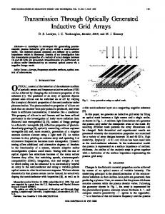
analysis (see, e.g., [65], [66] and references therein). Under this respect, PB SS noise analysis has a great potential as a means to develop and validate physically sound and reliable compact models, either in the form of equivalent circuit-based approaches or of black-box models. Similar remarks apply also to the case of LS noise analysis. In this regime, circuit designers very often exploit the following noise analysis technique: the device noise is described by the same models derived for SS operation as a function of the device (static) working point; since in LS conditions this becomes periodically time-varying, the stationary noise processes are modulated and transformed into cyclostationary fluctuations. This assumption, clearly, has to be proved by measurements and/or by PB LS simulations. The very process of modulation poses severe problems when nonwhite SS noise spectra are involved: as discussed in [6], [63], and [64], two interpretations are possible. Let us consider, for simplicity, a stationary SS noise process with power spectrum , where is a working point-dependent factor and is the impulse response of a properly defined linear time-invariant system taking into account the frequency dependence of the spectrum: for a . Process can be interpreted as white process, the output of the linear filtering of a unit white Gaussian noise according to the scheme in Fig. 3(a). In LS conprocess ditions, the working point becomes periodically time-varying, periodically modulates the noise and therefore factor process. Unfortunately, such a modulation can be performed at least in two different ways. is first modulated by and thus converted into • [see a cyclostationary process, then filtered by Fig. 3(b)]: this mechanism will be denoted as “MF” and with SCM [63], [64] as leads to process (13) is the th harmonic amplitude of the periodic where and denotes the element function of the SCM. is first filtered by , yielding the stationary • , then modulated by [see Fig. 3(c)]: process this mechanism will be denoted as “FM” and leads to with SCM [63], [64] as process (14) is the th harmonic amplitude of the periodic where . function is a low-pass function, it is apparent from (13) that the If MF modulation scheme yields an SCM with null elements apart , i.e., the baseband sideband, while the FM scheme from has a large enough number of harmonics (14), provided that (i.e., if the device is driven in nonlinear conditions), results in an SCM with several nonzero elements. Furthermore, for white SS processes (13) and (14) yield the same result as follows:
(15)
(a)
(b)
(c) Fig. 3. System interpretation of a noise process. (a) Stationary process for SS noise analysis. (b) Cyclostationary MF process for LS noise analysis. (c) Cyclostationary FM process for LS noise analysis.
On the other hand, the case of colored SS noise requires choosing between the two possible approaches. According to the literature, the FM approach is probably the most commonly applied in circuit simulators (see, e.g., [7], [38], and [67]), but the MF approach has been exploited as well, at least for noise (see e.g., [68] and [43]). In any case, it is widely recognized in the literature that a final solution of this problem still has to be found: an important step toward the completion of this process could, and should, be provided by LS PB models, at least for particular classes of devices and microscopic noise sources. The case of GR noise in a uniform device (a doped semiconductor sample) was discussed in [63] and [64], showing that the correct modulation approach to be applied to the SS Lorentzian microscopic noise sources, for direct GR processes, is the FM scheme. However, care should be exerted in generalizing this conclusion to any device class, as the following discussion suggests. As a case study, we shall consider the PB simulation of a pn diode: despite its simplicity, the bipolar nature of conduction in this device makes noise analysis in LS conditions complex. As shown in [22, ch. 4] for a long device, under low-injection conditions a closed-form analysis can be carried out, leading to an expression of the SS noise spectrum including both diffusion and GR noise. The well-known shot-like result is obtained [10] as (16) the saturation current of the where is the dc current, the small-signal admittance as a function junction, and of frequency. Under forward bias conditions and low operating frequency, (16) is approximated by the full shot expression .
640
IEEE TRANSACTIONS ON ELECTRON DEVICES, VOL. 50, NO. 3, MARCH 2003
Fig. 4. Frequency dependence of the SS current noise spectrum for the short pn junction. The solid line is the PB model, and the symbols are obtained by the full shot noise formula embedding the parasitic resistance of the neutral regions.
A first simulation is performed for a short Si abrupt pn cm , junction, with doping levels cm V s minority carrier mobilities and cm V s , minority carrier lifetimes s, cross section normalized to 1 cm , and side lengths 6 m: in this case, the GR noise contribution to the SS noise spectrum is negligible, and all of the shot-like behavior is due to diffusion noise. The short-circuit current noise spectrum for a forward bias of 0.5 V is shown in Fig. 4, where the PB simulation is compared to the result of the full shot noise model (the dc current is that evaluated by the PB simulation): the frequency dependence is due to the presence of the intrinsic device capacitances and of the series, parasitic of the neutral regions; the high-frequency plateau resistance was extracted is due to the thermal noise in such resistance. from small-signal analysis, obtaining a value of 1 m . The agreement is generally good, apart from a small discrepancy around 100 MHz, due to the fact that diffusion noise at those frequencies does not result any longer into full shot noise, since the device sides are not short anymore with respect to the (frequency-dependent) diffusion length. The same structure was then simulated under LS conditions with a one-tone voltage excitation superimposed to a 0.5-V dc component. The input tone was applied at two frequencies: MHz and GHz with tone amplitudes V and V, respectively. The LS steady-state analysis was perharmonics plus dc, so as to allow noise formed with ). simulation to be performed up to the third sideband ( Around , the device still exhibits SS white shot noise (see Fig. 4): the full shot noise formula can be amplitude modulated according to (15), obtaining a very good agreement with the results of the PB LS model, as shown in Table I for the diagonal and upper diagonal elements (independent of ) of the noise current SCM. The same kind of agreement holds also for the other off-diagonal elements. Concerning the excitation at 1 GHz, we report in Fig. 5 a comparison between the PB
TABLE I SCM ELEMENTS COMPARISON BETWEEN THE PB AND THE CIRCUIT MODELS FOR THE EXCITATION OF A SHORT DIODE AT f = 1 MHz. THE ELEMENTS ARE MEASURED IN 10 A 1Hz
model and the results of the circuit approach. In the latter, full and of shot noise is amplitude modulated and the effect of the junction (depletion) capacitance are embedded: the agreement is generally good, apart for a sideband frequency around 100 MHz, where already in SS conditions a discrepancy takes place. A more complex situation arises when intrinsically colored SS noise has to be modulated. As an example, we simulated a long Si pn junction, having the same parameters as the short s. The paraone, apart from the lifetimes
BONANI et al.: PHYSICS-BASED SIMULATION TECHNIQUES
641
Fig. 5. Diagonal elements of the noise current SCM as a function of the sideband frequency for the short diode simulated for an input tone with amplitude 0.1 V at 1 GHz: the solid line is the PB model, and the symbols are obtained by the modulated full shot noise formula embedding the parasitic resistance and the junction capacitance.
Fig. 6. Frequency dependence of the SS current noise spectrum for the long pn junction. The solid line is the PB model and the symbols are obtained by (16), embedding the parasitic resistance and the junction capacitance and using the distributed model for Y (!). Broken lines are generated by the full shot noise formula embedding the parasitic resistance of the neutral regions.
sitic resistance is . An SS simulation, including both diffusion and GR noise sources, was first carried out for a 0.5-V dc working point, and the device admittance and the noise spectrum were compared to the ones calculated according to the distributed analytical model (see [22]): the noise spectrum closely follows the theoretical estimation (16), as shown in Fig. 6, where the effect of the parasitic resistance, including its thermal noise, and of the junction capacitance have been added to the intrinsic noise spectrum. Broken curves in Fig. 6 show that poor agreement results if the full shot noise (white) approximation is exploited: this happens both if the approximate lumped is employed. or the accurate distributed expression for
An LS simulation, with a 0.2-V input tone at 10 MHz superimposed to the 0.5-V dc component, has then been carried out. The resulting diagonal elements of the SCM of the short-circuit noise current are reported in Fig. 7, where they are compared to the result of the modulation of (16), both following the MF and the FM schemes, and further including the effect of the parasitic resistance and of the junction capacitance: details on the implemented expressions can be found in [69]. Fig. 7 clearly shows that, at least for the device under test and the operating conditions taken into account, only the MF approach yields results in good agreement with the LS PB model. The FM scheme overestimates noise in the baseband sideband due to the high-pass
642
IEEE TRANSACTIONS ON ELECTRON DEVICES, VOL. 50, NO. 3, MARCH 2003
Fig. 7. Diagonal elements of the noise current SCM as a function of the sideband frequency for the long pn junction simulated for an input tone with amplitude 0.2 V at 10 MHz: the solid line is the PB model, the symbols are obtained by (16) modulated through the MF scheme and embedding the parasitic resistance and the junction capacitance, the dashed line is generated by (16) modulated through the FM scheme and embedding the parasitic resistance.
nature of the filtering function in (16). This result differs from that obtained for GR low-pass noise in a uniform resistor [63], [64], where the FM scheme has been proven to be the correct one. Furthermore, at a circuit simulation level, the FM scheme applied to other devices (e.g., microwave FETs [70]) has been demonstrated to reproduce the experimental results. These indications point out that the choice between the two modulation schemes is likely to depend on the device under investigation and on the nature of noise sources considered. PB simulations, supported by an extensive experimental characterization, can help in identifying a correct LS modeling approach for each device class. Moreover, noise measurement techniques should be exploited in order to directly characterize converted noise in LS conditions. This is particularly important in the modnoise, for which a fundamental white microscopic eling of noise source valid in all possible conditions has not yet been identified, though, as already remarked, a superposition of GR behavior at least noise sources can be exploited to provide on a limited frequency bandwidth. V. CONCLUSION A comprehensive review has been presented on the physicsbased numerical simulation of RF analog semiconductor devices, both in the small-signal and in the periodic, forced largesignal case. The connection between PB and circuit-oriented modeling has been discussed, showing that PB simulations can be exploited to validate compact models and purely circuit oriented approaches. Concerning LS noise, the customary strategy is to modulate the noise generators characterized in small-signal conditions. The modulation scheme itself is still not well established, at least for colored SS noise. We have discussed two modulation techniques, showing that the optimum strategy depends on the device class (bipolar or FET) considered, at least for intrinsically colored noise under small-signal conditions.
REFERENCES [1] M. W. Pospieszalski, “Modeling the noise parameters of MESFET’s and MODFET’s and their frequency and temperature dependence,” IEEE Trans. Microwave Theory Tech., vol. 37, pp. 1340–1350, Sept. 1989. [2] A. Cappy, “Noise modeling and measurement techniques,” IEEE Trans. Microwave Theory Tech., vol. 36, pp. 1–10, Jan. 1988. [3] G. Dambrine, J.-P. Raskin, F. Danneville, D. Vanhoenacker-Janvier, J.-P. Colinge, and A. Cappy, “High-frequency four noise parameters of silicon-on-insulator-based technology MOSFET for the design of low-noise RF integrated circuits,” IEEE Trans. Electron Devices, vol. 46, pp. 1733–1741, Aug. 1999. [4] A. van der Ziel, Noise in Solid-State Devices and Circuits. New York: Wiley-Interscience, 1986. [5] C. Dragone, “Analysis of thermal and shot noise in pumped resistive diodes,” Bell Syst. Tech. J., vol. 47, pp. 1883–1902, 1968. [6] A. Demir and A. Sangiovanni-Vincentelli, Analysis and Simulation of Noise in Nonlinear Electronic Circuits and Systems. Boston, MA: Kluwer, 1998. [7] V. Rizzoli and A. Neri, “State of the art and present trends in nonlinear microwave CAD techniques,” IEEE Trans. Microwave Theory Tech., vol. 36, pp. 343–365, Feb. 1988. [8] A. Demir, A. Mehrotra, and J. Roychowdhury, “Phase noise in oscillators: A unifying theory and numerical methods for characterization,” IEEE Trans. Circuits Syst. I, vol. 47, pp. 655–674, May 2000. [9] W. Shockley, J. A. Copeland, and R. P. James, “The impedance field method of noise calculation in active semiconductor devices,” in Quantum Theory of Atoms, Molecules, and the Solid-State, P.-O. Lowdin, Ed. New York: Academic, 1966. [10] K. M. van Vliet, “General transport theory of noise in pn junction-like devices—I: Three-dimensional Green’s function formulation,” SolidState Electron., vol. 15, pp. 1033–1053, 1972. [11] M. L. Tarng and K. M. van Vliet, “General transport theory of noise in pn junction-like devices—II: Carrier correlations and fluctuations for high injection,” Solid-State Electron., vol. 15, pp. 1055–1069, 1972. [12] H. S. Min, K. M. van Vliet, and A. van der Ziel, “General transport theory of noise in pn junction-like devices—III: Junction noise in p n diodes at high injection,” Phys. Stat. Sol. (a), vol. 10, pp. 605–618, 1972. [13] G. Ghione, E. Bellotti, and F. Filicori, “Physical noise modeling of majority-carrier devices: An adjoint network approach,” in IEDM Tech. Dig., Washington, DC, Dec. 1989, pp. 351–355. [14] G. Ghione and F. Filicori, “A computationally efficient unified approach to the numerical analysis of the sensitivity and noise of semiconductor devices,” IEEE Trans. Computer-Aided Design, vol. 12, pp. 425–438, 1993.
BONANI et al.: PHYSICS-BASED SIMULATION TECHNIQUES
[15] F. Bonani, G. Ghione, M. R. Pinto, and R. K. Smith, “An efficient approach to noise analysis through multidimensional physics-based models,” IEEE Trans. Electron Devices, vol. 45, pp. 261–269, Jan. 1998. [16] F. Bonani, S. Donati Guerrieri, G. Ghione, and M. Pirola, “A TCAD approach to the physics-based modeling of frequency conversion and noise in semiconductor devices under large-signal forced operation,” IEEE Trans. Electron Devices, vol. 48, pp. 966–977, May 2001. [17] F. Danneville, G. Dambrine, and A. Cappy, “Noise modeling in MESFET and HEMT mixers using a uniform noisy line model,” IEEE Trans. Electron Devices, vol. 45, pp. 2207–2212, Oct. 1998. [18] A. Cappy, F. Danneville, G. Dambrine, and B. Tamen, “Noise analysis in devices under nonlinear operation,” Solid State Electron., vol. 43, pp. 21–26, Jan. 1999. [19] ISE AG.. (2002) DESSIS. [Online]. Available: http://www.ise.ch/products/index.html. [20] Avant! Corporation. (2002) Taurus-Device. [Online]. Available: http://www.avanticorp.com/Avant!/SolutionsProducts/Products/Item/ 1,1500,192,00.html#. [21] F. Bonani and G. Ghione, “Generation-recombination noise modeling in semiconductor devices through population or approximate equivalent current density fluctuations,” Solid-State Electron., vol. 43, pp. 285–295, 1999. , Noise in Semiconductor Devices. Modeling and Simulation. [22] Heidelberg, Germany: Springer-Verlag, Springer Series in Advanced Microelectronics, 2001. [23] L. Nagel, “SPICE2: A computer program to simulate semiconductor circuits,” Electron. Res. Lab., Univ. California at Berkeley, UCB/ERL M520, 1975. [24] T. Quarles, “The SPICE3 implementation guide,” Electron. Res. Lab., Univ. California at Berkeley, UCB/ERL M89/44, 1989. [25] Agilent EEsof EDA. (2000) Advanced design system overview. [Online]. Available: http://eesof.tm.agilent.com/products/adsoview.html. [26] Cadence Design Systems. (2000) Spectre RF. [Online]. Available: http://www.cadence.com/products/spectrerf.html. [27] Applied Wave Research, Inc.. (2002) Microwave Office 2002. [Online]. Available: http://www.mwoffice.com/products/mwoffice.html [28] Avista Design Systems. (1999) SP/XL for RF and microwave design. [Online]. Available: http://www.avista.com [29] K. Mayaram, D. C. Lee, S. Moinian, D. A. Rich, and J. Roychowdhury, “Computer-aided circuit analysis tools for RFIC simulation: Algorithms, features, and limitations,” IEEE Trans. Circuits Syst. II, vol. 47, pp. 274–286, Apr. 2000. [30] A. Papoulis, Probability, Random Variables and Stochastic Processes. New York: McGraw-Hill, 1965. [31] P. Russer and S. Müller, “Noise analysis of linear microwave circuits,” Int. J. Numer. Mod., vol. 3, pp. 287–316, 1990. [32] R. A. Roher, L. Nagel, R. Meyer, and L. Weber, “Computationally efficient electronic-circuit noise calculation,” IEEE J. Solid-State Circuits, vol. SC-6, pp. 204–212, 1971. [33] F. H. Branin, “Network sensitivity and noise analysis simplified,” IEEE Trans. Circuit Theory, vol. CT-20, pp. 285–288, 1973. [34] H. C. de Graaf and F. M. Klaassen, Compact Transistor Modeling for Circuit Design. Berlin, Germany: Springer-Verlag, 1990. [35] F. Danneville, H. Happy, G. Dambrine, J.-M. Belquin, and A. Cappy, “Microscopic noise modeling and macroscopic noise models: How good a connection?,” IEEE Trans. Electron Devices, vol. 41, pp. 779–786, May 1994. [36] P. Heymann, M. Rudolph, H. Prinzler, R. Doerner, L. Klapproth, and G. Böck, “Experimental evaluation of microwave field-effect-transistor noise models,” IEEE Trans. Microwave Theory Tech., vol. 47, pp. 156–163, Feb. 1999. [37] S. Maas, Nonlinear Microwave Circuits. Norwood, MA: Artech House, 1988. [38] V. Rizzoli, F. Mastri, and D. Masotti, “General noise analysis of nonlinear microwave circuits by the piecewise harmonic balance technique,” IEEE Trans. Microwave Theory Tech., vol. 42, pp. 807–819, May 1994. [39] M. J. O. Strutt, “Noise figure reduction in mixer stages,” Proc. IRE, vol. 34, no. 12, pp. 942–950, Dec. 1946. [40] A. van der Ziel and R. L. Waters, “Noise in mixer tubes,” Proc. IRE, vol. 46, pp. 1426–1427, 1958. [41] D. N. Held and A. R. Kerr, “Conversion loss and noise of microwave and millimeter-wave mixers: Part I—Theory,” IEEE Trans. Microwave Theory Tech., vol. 26, pp. 49–55, Feb. 1978. [42] M. Okumura, H. Tanimoto, T. Itakura, and T. Sugawara, “Numerical noise analysis for nonlinear circuits with a periodic large signal excitation including cyclostationary noise sources,” IEEE Trans. Circuits Syst. I, vol. 40, pp. 581–590, Sept. 1993.
643
[43] J. Roychowdhury, D. Long, and P. Feldmann, “Cyclostationary noise analysis of large RF circuits with multitone excitations,” IEEE J. SolidState Circuits, vol. 33, pp. 324–336, Mar. 1998. [44] C. M. van Vliet, “Macroscopic and microscopic methods for noise in devices,” IEEE Trans. Electron Devices, vol. 41, pp. 1902–1915, Nov. 1994. [45] F. N. Hooge, “1=f noise sources,” IEEE Trans. Electron Devices, vol. 41, pp. 1926–1935, Nov. 1994. [46] P. H. Handel, “Fundamental quantum 1=f noise in semiconductor devices,” IEEE Trans. Electron Devices, vol. 41, pp. 2023–2033, Nov. 1994. [47] J. P. Nougier, “Fluctuations and noise of hot carriers in semiconductor materials and devices,” IEEE Trans. Electron Devices, vol. 41, pp. 2034–2049, Nov. 1994. [48] S. Selberherr, Analysis and Simulation of Semiconductor Ddevices. Berlin, Germany: Springer-Verlag, 1984. [49] C. Jungemann, B. Neinhüs, and B. Meinerzhagen, “Hierarchical 2D DD and HD noise simulation of Si and SiGe devices—Part I: Theory,” IEEE Trans. Electron Devices, vol. 49, pp. 1250–1257, July 2002. [50] P. Shiktorov, E. Starikov, V. Gru˘zhinskis, T. Gonzlez, J. Mateos, D. Pardo, L. Reggiani, L. Varani, and J. C. Vaissière, “Langevin forces and generalized transfer fields for noise modeling in deep submicron devices,” IEEE Trans. Electron Devices, vol. 47, pp. 1992–1998, Oct. 2000. [51] F. Bonani and G. Ghione, “Noise modeling for PDE based device simulations,” in Proc. 16th Int. Conf. on Noise in Physical Systems and 1/f noise, Bosman, Ed. Gainesville, FL, Oct., 22–25 2001, pp. 631–636. [52] C. Jungemann, B. Neinhüs, S. Decker, and B. Meinerzhagen, “Hierarchical 2D RF noise simulation of Si and SiGe devices by Langevin-type DD and HD models based on MC generated noise parameters,” in IEDM Tech. Dig., Washington, DC, Dec., 2–5 2001, pp. 481–484. [53] M. R. Law. Current floops/floods manual. [Online]. Available: http://www.tec.ufl.edu/flooxs/ [54] Y. Lin, L. Wang, M. Obrecht, and T. Manku, “Quasi-3D device simulation for microwave noise characterization of MOS devices,” in IEDM Tech. Dig., San Francisco, CA, Dec. 6–9, 1998, pp. 77–80. [55] S. Donati, M. A. Alam, K. S. Krisch, S. Martin, M. R. Pinto, H. H. Vuong, F. Bonani, and G. Ghione, “Physics-based RF noise modeling of submicron MOSFETs,” in IEDM Tech. Dig., San Francisco, CA, Dec. 6–9, 1998, pp. 81–84. [56] J.-S. Goo, C.-H. Choi, F. Danneville, E. Morifuji, H. S. Momose, Z. Yu, H. Iwai, T. H. Lee, and R. W. Dutton, “An accurate and efficient high frequency noise simulation technique for deep submicron MOSFETs,” IEEE Trans. Electron Devices, vol. 74, pp. 2410–2419, Dec. 2000. [57] J. Sato-Iwanaga, K. Fujimoto, Y. Ota, K. Inoue, B. Troyanovsky, Z. Yu, and R. W. Dutton, “Distortion analysis of GaAs MESFET’s based on physical model using PISCES-HB,” in IEDM Tech. Dig., San Francisco, CA, Dec. 1996, pp. 163–166. [58] B. Troyanovsky, “Frequency domain algorithms for simulating large signal distortion in semiconductor devices,” Ph.D. dissertation, Stanford Univ., Stanford, CA, 1997. [59] B. Troyanovsky, Z. Yu, and R. W. Dutton, “Physics-based simulation of nonlinear distortion in semiconductor devices using the harmonic balance method,” Comput. Methods Appl. Mech. Eng., vol. 181, pp. 467–482, 2000. [60] F. Bonani, S. Donati Guerrieri, G. Ghione, and M. Pirola, “A new approach to the physics-based noise analysis of semiconductor devices operating in large signal, (quasi) periodic regime,” in IEDM Tech. Dig., Washington, DC, Dec. 7–10, 1997, pp. 321–324. [61] J. E. Sanchez, G. Bosman, and M. E. Law, “Device simulation of generation-recombination noise under periodic large-signal conditions,” in IEDM Tech. Dig., Washington, Dec. 2001, pp. 477–480. [62] A. Cappy and W. Heinrich, “High-frequency FET noise performances: A new approach,” IEEE Trans. Electron Devices, vol. 36, pp. 403–409, 1989. [63] F. Bonani, S. Donati Guerrieri, and G. Ghione, “Fundamental and equivalent cyclostationary microscopic noise sources for LS device simulation,” in Proc. 16th Int. Conf. on Noise in Physical Systems and 1/f Noise, G. Bosman, Ed. Gainesville, FL, Oct. 22–25, 2001, pp. 649–652. , “Noise source modeling for cyclostationary noise analysis in [64] large-signal device operation,” IEEE Trans. Electron Devices, vol. ED-49, pp. 1640–1647, Sept. 2002. [65] A. J. Scholten, H. J. Tromp, L. F. Tiemeijer, R. van Langevelde, R. J. Havens, P. W. H. de Vreede, R. F. M. Roes, P. H. Woerlee, A. H. Montree, and D. B. M. Klaassen, “Accurate thermal noise model for deep-submicron CMOS,” in IEDM Tech. Dig., Washington, DC, Dec. 5–8, 1999, pp. 155–158.
644
[66] F. Bonani, S. Donati Guerrieri, and G. Ghione, “Green’s function approach to MOS physics-based compact noise modeling,” Fluctuation Noise Lett., vol. 1, no. 1, pp. R51–R63, 2001. [67] S. Heinen, J. Kunisch, and I. Wolff, “A unified framework for computeraided noise analysis of linear and nonlinear microwave circuits,” IEEE Trans. Microwave Theory Tech., vol. 39, pp. 2170–2175, Dec. 1991. [68] A. Demir, E. W. Y. Liu, and A. Sangiovanni-Vincentelli, “Time-domain non Monte Carlo noise simulation for nonlinear dynamic circuits with arbitrary excitations,” IEEE Trans. Computer-Aided Design, vol. 15, pp. 493–505, 1996. [69] F. Bonani, S. Donati Guerrieri, and G. Ghione, “Compact modeling of cyclostationary noise in semiconductor devices: A critical discussion,” in IEDM Tech. Dig., paper no. 5.7., pp. 133–136. [70] V. Rizzoli, F. Mastri, and C. Cecchetti, “Computer aided noise analysis of MESFET and HEMT mixers,” IEEE Trans. Microwave Theory Tech., vol. 37, pp. 1401–1410, Sept. 1989.
Fabrizio Bonani (S’89–M’91–SM’02) was born in Torino, Italy, in 1967. He received the Laurea degree (cum laude) and the Ph.D. degree in electronic engineering from Politecnico di Torino, Italy, in 1992 and 1996, respectively. Since 1995, he has been with the Electronics Department of the same institution, first as a Researcher and now, since 2001, as an Associate Professor of Electronics. His research interests are mainly devoted to the physics-based simulation of semiconductor devices, with special emphasis on the noise analysis of microwave field-effect and bipolar transistors, and to the thermal analysis of power microwave circuits. Part of his research concerns the analysis and simulation of nonlinear dynamical systems. From October 1994 to June 1995, he has been with the ULSI Technology Research Department of Bell Laboratories, Murray Hill, NJ, as a consultant, working on physics-based noise modeling of electron devices.
IEEE TRANSACTIONS ON ELECTRON DEVICES, VOL. 50, NO. 3, MARCH 2003
Simona Donati Guerrieri (M’97) was born in 1969 in Milan, Italy. She received the degree in theoretical physics from the University of Milan, Milan, Italy, in 1993 and the Ph.D. degree in electron devices from University of Trento, Trento, Italy, in 1999. She is presently working as a Researcher in the Electronics Department of Politecnico of Torino, Torino, Italy, where she joined the microwave electronics group. Her research interests include the modeling and simulation of microwave solid-state devices, including physics-based noise analysis, and the RF and microwave integrated circuit design.
Giovanni Ghione (M’87–SM’94) was born in 1956 in Alessandria, Italy. He received the degree cum laude in electronic engineering from Politecnico di Torino, Torino, Italy, in 1981. In 1983 he became a Research Assistant with Politecnico di Torino and from 1987 to 1990 an Associate Professor with Politecnico di Milano, Milan, Italy. In 1990 he joined the University of Catania as Full Professor of Electronics, and since 1991 he has covered the same position again at Politecnico di Torino, II Faculty of Engineering. Since 1981, he has been engaged in Italian and European research projects (ESPRIT 255, COSMIC and MANPOWER) in the field of active and passive microwave computer-aided design. His present research interests concern the physics-based simulation of active microwave and optoelectronic devices, with particular attention to noise modeling, thermal modeling,and active device optimization. His research interests also include several topics in computational electromagnetics, including coplanar component analysis. He has published more than 200 papers and book chapters and four books in the above fields. Prof. Ghione is a member of the AEI (Associazione Elettrotecnica Italiana) and a member of the Editorial Board of the IEEE TRANSACTIONS ON MICROWAVE THEORY AND TECHNIQUES.