Time Absolute Error (ITAE) and Integral Time. Square Error (ITSE) are determined. Performances of these techniques are compared under same transient levels.
COMPUSOFT, An international journal of advanced computer technology, 5 (12), December-2016 (Volume-V, Issue-XII)
ISSN:2320-0790
PI, PID Controllers with Performance Index for Speed Control of DC Motor Santosh Kumar Suman Department of Electrical Engineering, Rajkiya Engineering College, Kannauj, UP,India Abstract: DC motor plays an important role in industry and domestic application. Thus, the speed control of DC shunt motor is a prime task. This paper gives a comparison of the performance of conventional proportional integral (PI) and proportional integral derivative (PID) for speed control of DC shunt motor. investigated for speed control of DC motor. At the start PID controller parameters for different tuning techniques are involved and then applied to the DC motor model for motion (speed) control. Simulation results are display, using these controllers, objective of this paper, the performance of a choose dc motor controlled by a proportional-integralderivative (PID) controller is below the similar transient conditions and performances are compared. Keywords - DC motor, PID controller, PID tuning, performance index. I. Introduction The improvement of great torque performance the motor drives is very essential in built-up and manufacturing used and as well as other purpose applications such as electric trains steel rolling mills, and, automatic manipulators [1].Purpose of this paper is to control the speed of dc motor for the reason that dc motor has been commonly used in commercially even though its maintenance costs are higher than other motors. Generally, a large torque performance the dc motor drive must have superior dynamic speed control tracking and load variable to perform task. The DC motor drives, because of their effortlessness, ease of application, high stability, good cost and flexibilities have long been a spine of manufacturing applications, and residential appliances where position control and speed control of motor are required. The DC motor drives are less versatile with a single phase transfer from AC to DC. An ahead instance the speed torque characteristics of DC motors drive are preferable to that of AC motors drive. [1]. PID controllers cover numerous significant types. It provides feedback. As PD improves transient response (i.e. it be able to expect the changes during derivative action) and PI improves performance of steady state response (i.e. reduce steady state offset during integral action or law), combination of two may be used to progress overall time response of the system. In addition to this, PID controllers have very uncomplicated control structure and are less high-priced [2]. Objective of this paper different PID controllers are
verified for speed control of DC motor. Integral Time Absolute Error (ITAE) and Integral Time Square Error (ITSE) are determined. Performances of these techniques are compared under same transient levels. The paper is organized as follows. In Section II, model of DC motor is presented. Brief introduction of PID controller is given in Section III. Simulation results are shown as figure and table in Section IV, followed by conclusion in Section V. II.
SPEED CONTROL METHODS FOR DC MOTOR
The motor speed can be controlled by controlling the armature voltage or the field voltage. It is obvious that the speed control is possible by varying the following. Flux per pole,φ (Flux Control). Resistance of armature circuit, Ra (Rheostatic Control). Armature applied voltage, (Voltage Control). The usages of the above methods (with resistance control) have some disadvantages such as a large amount of power is wasted in the controller resistance. Hence, the efficiency is decreased. This needs expensive arrangement for dissipation of heat produced in the controller resistance. It gives speeds below the normal speed. Therefore, these methods are less adaptive. Electronic techniques are used for speed control. These techniques
2241
COMPUSOFT, An international journal of advanced computer technology, 5 (12), December-2016 (Volume-V, Issue-XII)
provide higher efficiency, greater reliability, and quick response.
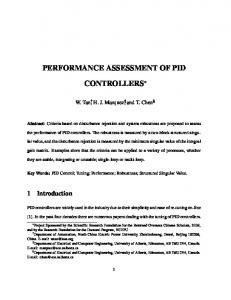
= angular speed (rad/s). = motor torque (N m). θ = angular position of rotor shaft (rad). = rotor inertia (kg m2). = viscous friction coefficient ( s/rad). = motor torque constant (Nm/A). = back emf constant (V s/rad).
III. MODELING OF DC MOTOR The DC motors are highly unfailing and capable because of the some good quality like high starting torque, efficient response and linear controllability. The term speed control stand up for planned speed difference carried out physically or automatically. The DC motor drives are mainly appropriate for broad range of Speed control and adjustable speed drives [3]. Shunt D.C. Machines The field coils of a shunt D.C. machine are connected in parallel to the armature coils. Therefore, the Transient in the armature circuit is simultaneous with the Brief in the field circuit. A circuit model of a Shunt D.C. Motor is shown in Figure.1.below
Numerical Values The DC motor under study has the following specification and parameters for speed control. A. Specifications 2hp,230 volts,8.5 amperes,1500rpm B. Parameters Ra=0.45ohm,La=0.035H,Kb=0.5volt/(rad/sec), J=0.022Kg-m2/rad,B=0.2×10-3N-/(rad/sec). III.
PID CONTROLLER
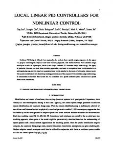
PID Controller is a basic control loop of feedback mechanism and is widely used in control system. The disparate symptoms of a the DC motor such as diffusion and invention can degrade the performance of traditional controllers [4].PID Controllers use three basic types of parameter or modes: Proportional (P), Integral (I) and Derivative (D).While proportional and integral control is used as single control approach, a derivative control used is that it improves the transient response of the system. In this paper it is implemented a technique to control the speed of DC motor drive which above is shown in Figure.3. The speed error between the references speed and the actual speed is given as input to a PID controller. The PID controller working on the changes in error its productiveness, to control the process input such that the error is reduce. PID controller is also known as the three-term of main controller parameter, whose transfer function is commonly written in the parallel form given by equation (12) or the ideal form is given by equation (2)[5]. General form of the Transfer function of a PID controller is given as,
Fig.1. Shunt D.C. Motor
(1) (2) (3)
(4) (5)
(7)
Show the transfer functions (5) and overall transfer function dc shunt motor is given below in equation (6).
(8) (9)
(6)
A.
Where = armature resistance (Ω- ohm). = armature inductance (H-henry). = armature current (A). = armature voltage (V). = back emf (V).
2242
Proportional control action It is simplest class of continuous control law. The controller output u (t) is made proportional to the actuating error signal e (t). The proportional gain is also called proportionality constant, it is denoted by KP and the control action is written by
COMPUSOFT, An international journal of advanced computer technology, 5 (12), December-2016 (Volume-V, Issue-XII)
u (t) =KP e(t)
(10)
Steady state error less than 1%
IV. Where e (t) = r (t)-y(t) for unity response system(t) is the error signal ,r(t) is reference input of the system, and y(t) is the output of the system.
FIGURES AND TABLES Table. I. Tuning PID Parameters of the Controllers Tuning Metho d
B. Integral control action In this a controller with integral control action, the value of the controller productivity is changed at a rate proportional to the actuating error signal. If there zero steady state error is desirable, this means a control mode that is a function of error will be buildup.
Controller s
KC
tD
tc
PI
10.14
11.32
-
PID
9.10
PI
ZNOPSP
ZNOPDR
PID
ITAE
PD PID PI
6.815 14.24 0 4.12 -0.52 3.88
ITSE
PID
1.42
(11)
U(t)=
13.14 0 190
-0.12 -
131
-0.21
54 4.60 58
4.52 3.91 2
5.15
(12)
Where is KI an integral gain constant. C. Derivative control action The used of integral law is sufficient to reduce the steady error to zero however, the dynamic or the transient response may still be broke because of large oscillations, overshoots etc. The derivative control law, sometimes called rate control, is therefore, the magnitude of the controller output is proportional to the rate of change of the actuating error signal. U (t) =
(13)
TABLE II RESULT OF STEP RESPONCES Tuning Method
Controllers
%Mp
Tr(sec)
Ts(sec)
PI
23.30
1.32
1.20
PID
17.5
.50
2.40
ZNOP-SP
ZNOPDR
Figure.2 .PID Controller with System ITAE
Where e = Error signal Kp = Proportional Constant Ki= Integral Constant Kd = Derivative Constant
ITSE
PI
79.85
2.10
2.470
PID
43.20
1.25
0.187
PI
3.12
0.54
1.354
PID
0.82
0.60
0.246
PI
34.58
0.82
0.254
PID
6.12
0.24
11.01
V. CONCLUSION In this paper, we have discus different type of PID fine-tuning techniques are established for speed control of DC motor. Two different transient conditions are tested for all the controllers are responses are compared. From simulation result it is observed that the performance of PI controller is satisfactory compared to other controllers. It is
u(t) =
We would like that the PID controller to propitiate the follow criteria: Settling time less than 2 sec Overshoot less than 5%
2243
COMPUSOFT, An international journal of advanced computer technology, 5 (12), December-2016 (Volume-V, Issue-XII)
believed that the study carried out in this paper is useful to control engineer to recognize the effect of different PID tuning techniques.
REFERENCES [1] K. Ogata (2009) “Modern Control Engineering, 4th Edition”, Dorling Kindersley Pvt. Ltd., India. [2] V. Antanio, “Research Trends for PID Controllers”, ACTA Polytechnicia Vol. 52 No. 5/2012. [3] Prof. Aziz Ahmed, Yogesh Mohan and Aasha Chauhan, Pradeep Sharma, “Comparative Study of Speed Control of D.C. Motor Using PI, IP, and Fuzzy Controller,” International Journal of Advanced Research in Computer and Communication Engineering Vol. 2, Issue 7, July 2013. [4] Ang, K.H, Chong, G.C.Y. and Li, Y, “PID control system analysis design and technology”, IEEE Transactions on Control Systems Technology 13(4):pp. 559-576, 2005. [5] Jamal A. Mohammed, “ Modeling, Analysis and Speed Control Design Methods of a DC Motor” ,Eng. & Tech.Journal ,vol .29,no.1,2011. [6] H. Guoshing, L. Shuocheng, “PC-based PID Speed Control in DC Motor”, IEEE Trans. on Audio, Language and Image Processing, 2008, pp. 400-407. [7] U. Neethu, V.R. Jisha, “Speed Control of Brushless DC Motor: A Comparative Study”, Proc. of IEEE Int. Conf. on Power Electronics, Drives and Energy Systems, 2012, pp. 1-5. [8] ditya Pratap Singh, “Speed Control of DC Motor using Pid Controller Based on Matlab” Innovative Systems Design and Engineering, Vol.4, No.6,2013. [9] Kapinjay Ucharia, Himmat Singh, “Performances and Analysis of D.C Machine using PID Controller” International Journal of Scientific Engineering and Technology Volume No.3 Issue No.3, pp : 235–239, 1 March 2014. [10] Santosh Kumar Suman and Vinod Kumar Giri, “Speed Control of DC Motor Using Optimization Techniques Based PID Controller”, 2016 International Conference on Engineering and Technology (IEEE-ICETECH-2016) 17th & 18th March TN, India, Coimbatore, pp.1193 1999,2016.
2244