PinBus Interface for Interoperable, Grid-Responsive Devices Donald Hammerstrom Pacific Northwest National Laboratory 902 Battelle Blvd, MSIN K1-85 Richland, WA 99352
[email protected]
Keywords: Appliance interface, interoperability, demand response Abstract A very simple appliance interface was suggested by this author and his co-authors during Grid-Interop 2007. The approach was based on a successful collaboration between utilities, a major appliance manufacture, and the manufacturer of a load control module during the U.S. Department of Energy’s Grid Friendly™ Appliance project. The suggested approach was based on the assumption that demand-response objectives could be effectively communicated to and from many small electrical loads like appliances by simply agreeing on the meaning of the binary states of several shared connector pins. It was argued that this approach could pave the way for a wave of demandresponse-ready appliances and greatly reduced expenses for utilities’ future demand-response programs. The approach could be supported by any of the many competing serial communication protocols and would be generally applicable to most end-use devices. 1. BACKGROUND The PinBus interface protocol is based on the successful communication of autonomously generated control signals to appliances during the Grid Friendly™ Appliance Project [1]. In this project, 150 Whirlpool Corporation clothes dryers and 50 water heaters were modified to receive and respond to a signal from the Grid Friendly autonomous controller. The voltage of a shared connection pin was simply reduced to zero to indicate the presence of a low frequency condition on the electric power grid. Recognizing how elegantly the simple control signal had been communicated by the electrical voltage state of a limited number of pins, collaborators from PNNL, Whirlpool Corporation, and Portland General Electric presented the approach’s attributes and a compelling business case for the approach at the 2007 Grid-Interop Forum [2]. The author has extended and more fully defined this concept and opportunity funded by the U. S. Department of Energy [3]. The development of this interface protocol is being undertaken during a global push to make electric power grids smarter. There is a consequent desire to create more
flexible, responsive populations of end-use devices, a cooperative grid system that better manages available energy, power, and infrastructure. Ideally, the development of such a flexible, responsive system will be facilitated by low cost means to communicate to the multitude of potentially responsive end-use devices. The components of such a system are preferably interoperable and interchangeable, thus facilitating competition that further drives downward the system costs. Furthermore, such communications must be secure. The PinBus approach facilitates these needs of a smart grid. 2.
EXISTING CHALLENGES ADDRESSED BY PINBUS The following issues presently limit that application of demand response to small loads and appliances and are addressed by the PinBus approach. Demand responsiveness is expensive. The control of small devices like appliances can bear only a small expense. At pennies per kWh, the expense of energy and electric power justifies few demand-response applications. Therefore, utility energy programs typically control only the largest residential appliance types. Even so, the expenses borne by retrofit products and aftermarket engineering and installation make such programs only marginally costeffective. But the expenses would be greatly reduced if the devices were installed ready to respond to energy programs, and more and even smaller devices like white goods appliances could be made responsive to the grid if necessary modifications were performed on the manufacturing floor, where labor is relatively inexpensive. Durability and Obsolescence. Devices like appliances endure much longer than nearly any digital technology or protocol has proven to endure. The smart grid involves the application of digital intelligence—computers—throughout the power grid. But there is a fundamental mismatch between the life expectancies of grid hardware and the very short life expectancies of most digital electronic devices and their software and protocols. PinBus minimizes the need for digital intelligence within the device. Interoperability. An interface to small devices like appliances must be interoperable. The communication interface should be similarly applied to most devices.
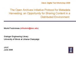
Interfaces providing different functions and made by different vendors should be interchangeable and applicable to many device types and models. And the interface should be amenable to multiple existing and future use cases. Furthermore, the preferred solutions will provide flexibility to all stakeholders. Appliance manufacturers should be allowed to change their appliances’ preferred communication protocol without redesigning their products. Utilities should be allowed to change their incentive programs to suit their emerging use cases. Security. The interface must be secure from intentional and accidental threats. Communication itself has been shown to increase threats from malicious and accidental causes. Simplicity breeds security. Because PinBus is unable to communicate unique identifying information across its boundaries, it should not be as vulnerable to cyber security threats as are other protocols that rely on rich serial communication of specific, identifiable information. Similarly, a customer’s privacy is protected when specific information about his appliances and habits remains unshared. 3. PRINCIPLES OF THE PINBUS APPROACH This section lists important attributes or characteristics of PinBus. 3.1. PinBus System Components A PinBus system is comprised of (1) A responsive device that provides and hosts a PinBus interface, (2) A removable, interchangeable interface module that plugs into the responsive device and converts its PinBus signals into another standard communication protocol, and (3) an entity that communicates to the interface module (see Figure 1). Examples of entities that would communicate to the interface modules could include utilities, aggregators, home gateways, or home energy managers. The responsive devices may include electric loads, distributed generators (including renewable generation), and simple energy indicators. Entity
Comm. Protocol
Use Case
Interface Module PinBus
PinBus
Application
Appliance
Figure 1. Components of a PinBus System 3.2. PinBus Supports Bi-directional Communication PinBus communication is inherently bi-directional. The wired-OR physical protocol is used, which means bus
conflicts will not create harm can be detected. In wired-OR logic, any terminus may assert a zero by forcing the condition of the connection to zero potential, but no party may assert a “1” state. Therefore, any party may assert its own zero and may read zeros asserted by other parties that share the connection. In principal, more than two parties could share the PinBus bus, but such an extension would necessarily require further specification of signal timing. The advantage of allowing multiple parties to share the PinBus bus would be that multiple applications—say from a local home manger, a neighborhood manager, an autonomous controller, and a utility—could all benefit from responses of a shared device. 3.3. PinBus Devices Use from 0ne to Eight Pins PinBus protocol allows and supports device communication using from one to eight device pins. Very simple devices like water heaters can respond adequately using just one pin. Additional pins allow for richer interactions, including acknowledgements, device identification, service requests, and communication of price level bids and incentives. While the devices can be configured for fewer than eight pins, every interface module must be able to communicate with any device and must therefore support all eight pins. When an interface module is connected to a device that has a reduced pin count, it learns the number of device pins and simplifies its own communications to use only those device pins that are available from the device. 3.4. PinBus Supports Transactive Price Control PinBus supports bid and price behaviors of the type that are needed for transactive control. Transactive control is a dynamic, interactive system of price control where devices bid their availability or need for power, which in turn affects the resultant price that is distributed to the responsive devices [4]. PinBus devices do not themselves receive and bid price, but a PinBus device is capable of stating its relative degree of satisfaction (i.e., its bid) and react accordingly to price using eight discrete levels. If necessary, it is the interface module (or another intelligent agent in the system) that converts monetary bids and prices to and from these discrete levels. So, a PinBus device communicates bids and prices using relative terms ranging from “extremely negative” to “extremely positive”. The use of both positive and negative level ranges anticipates smart PinBus devices that will respond to both high prices and low priced opportunities. 3.5. PinBus Communicates Desired Grid Outcomes PinBus communicates objectives and outcomes, not devicespecific directives. One of the keys to the simplification offered by PinBus is its recognition that the electric power grid asks responsive devices to perform relatively simple and few tasks. While some competing protocols provide
impressive bandwidth for the specific control of device components (e.g., “turn off dryer heating element”), PinBus communicates only high level objectives (e.g., “the grid is short on available power”, or “the grid needs VAr support immediately and for a short duration”). The responsive PinBus devices respond with simple acknowledgements and bids that reveal their present availability and need for real or reactive power. PinBus communicates nothing that is device-specific and therefore does not itself rely on unique addressing. 3.6. PinBus Might be Least Expensive Approach The PinBus approach could prove to be the least expensive approach to achieving demand-response-ready devices. The PinBus approach pushes risks and expenses outside the appliance or device. New appliances should be inexpensively augmented to support PinBus. The application engineer has options for numbers of pins to support and can implement the simplest PinBus interfaces without a microprocessor. It is assumed that a device would be most economically available if product models were delivered with the PinBus interface. Modest expenses would then be borne through the application of the interchangeable interface modules to the responsive devices, but these expenses would be borne by those who wish to control the device and only for those devices that are truly used. Additional savings should be expected from the approach’s universality and endurance as a simple standard. Development, for example, would be expedited because there is no need for the device developer to reveal and negotiate contextual and semantic meanings of communicated signals. 3.7. PinBus is a Commodity Approach to Control PinBus allows for various levels of device processor intelligence, including none. A one-pin device may be implemented with direct control of a power relay. Simple applications can be designed with logic only and no microprocessor. The PinBus approach is reducible to an application-specific integrated circuit (ASIC) that would further simplify the application developers’ development tasks. Process-oriented devices, especially those that interact regularly with humans, would likely require richer control and microprocessors. 3.8. Respects Customer and Manufacturer Privacy PinBus respects the sanctity of the device manufacturers’ relationship with its customers. The device manufacturer is solely responsible to determine the best response available from his product models. The PinBus protocol allows the device owner to temporarily override requested responses. Nonetheless, energy program mangers can ask for and receive through PinBus acknowledgements that devices are available and responding.
3.9. Interoperable, Interchangeable Modules PinBus interface modules are identical for all device applications. This means that there should be only one (e.g., ZigBee®-to-PinBus) interface module and not unique versions of such module by device type and by utility energy program. This is an important key to achieving interoperability. 4. PINBUS INTERFACE PROTOCOL Table 1 defines the meanings of PinBus pins from the perspectives of the device and the utility sides. # 7 6 5 4 3 2 1 0
Table 1. PinBus Pin Interpretations Device-Side Utility-Side Active / Inactive Real Idle / Active Power Control Hold (or Request Info.) / Overridden / Listening Release Last Request Bid from -4 “extremely Price (Value) from -4 negative” to 3 “extremely “extremely negative” to 3 positive” (or ID) “extremely positive” Ack. / Not Ack. Reactive Active / Inactive Reactive Power Request (or ID) Power Control Ack. / Not Ack. Real Short / Long Duration Power Request (or ID) Anticipated Maint. Needed / OK Respond Immediately / As (or ID) Soon as Possible
4.1. Interpretation Depends on Perspective The interpretation of a pin’s meaning depends on one’s perspective. The meaning of a pin’s state must be inferred from the utility and device sides. As will be discussed in the next section, the device and utility sides may assert pins that transition from one state to another, which transition is interpreted by the other side of the interface. Because wired-OR logic has been employed, the device or utility sides need only sample the pins to quickly assess any pin conditions that are being asserted by the other side. Therefore, the most important pin 7, for example, may be used by the device to show whether its application is consuming energy and by the utility side to request an energy response. Perspective must be considered. 4.2. Pin Meanings Each pin has an assigned attribute, or assigned attributes, that it is responsible to convey. One pin conveys to the device whether an energy response is in effect; another pin is used by the utility side to request a bid and acknowledgement from the device. While more data could be communicated if the pins simply represented a byte of data (i.e., up to 256 unique bytes), doing so would have (1) denied the generalized use of fewer than 8 pins, (2) limited bi-directional communication across the bus, and (3) violated an important principle and advantage of PinBus,
which was to avoid the communication of rich, devicespecific information.
sides of the PinBus interface can initiate notification. Most often, no notification will be asserted or requested and the notification status will be idle. However, the device can initiate an override-and-identify condition to let the utility side know its identity or announce that a request has been overridden. The utility side can request acknowledgement and bids from the device. The assertion and release of a notification state by either the device or utility side should be followed by a corresponding notification request from the other. Thereby, notification requests can be used to invite a bid or identification notification across the interface.
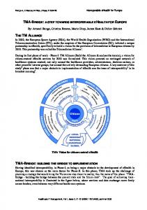
4.3. Devices Support from One to Eight Pins An interface module must support the full set of eight pins, but device applications are permitted to use as few as one pin. The interface module infers the number of pins from device responses and thereafter reduces the complexity of its communications according to the number of active pins provided by the device. The types of interactions that can be supported by devices having from one to eight PinBus pins are listed in Table 2. Table 2. Capabilities that can be Communicated across the PinBus Interface with Various Numbers of Device Pins #Pins Utility Side Device Side Power curtailment 1 Reveal on/off status requests Acknowledge power curtailment requests Hold power 2 Reveal override of power curtailment requests curtailment requests Bi-directional real Acknowledge bi-directional power requests real power requests 3-5 Reveal 2-8 price or Bid for service using 2-8 value levels discrete levels Bi-directional reactive Acknowledge bi-directional 6 power requests reactive power requests Reveal duration and Alert system / request 7-8 urgency of requests service 4.4. State Transition Definitions Refer to the complete state transition diagram in Figure 2. The lines between the 15 allowed states represent the important pin and originator or the state transition. For example, “D[P6]” indicates that the device (D), not the utility side (U), initiates the transition, and it is the status of pin number 6 that is used to initiate or reverse the transition. The three unique pairings of numbers that accompany the states were useful in determining the number of unique and important states and might prove useful during future device application development. The three numbers refer to operational, notification, and response statuses, respectively. These status attributes and corresponding numbers are defined here and summarized in Table 3.
Operational status—whether the device is active (i.e., on) or not. The device is solely responsible to determine its operational status, but the operational status can be influenced or directly controlled by response requests received by the device. The allowed device operational statuses are active, inactive, or unknown.
Notification status—whether the device or utility sides have requested notification. Either the device or utility
Response status—the utility side may assert a request for a modification of real power consumption, reactive power consumption, or both real and reactive power consumption. If no response is being requested by the utility side, the response status remains idle. The device may acknowledge or choose to override the requested change in real or reactive power, but these elections by the device do not change the response status condition. Table 3. Set of Unique State Status Identifiers Status \ #
0
1
2 3 Off / Not Operational Unknown On / Active Inactive Allowed Override Not Acknowledge Notification Unknown & Allowed & Bid Identify Both Reactive Real & Real Power Response Unknown Power Reactive Request Request Request
4 Idle
Idle
The available states that can be transitioned into by the device or interface module (utility side) are determined by the present state, by the number of pins supported by the present device, and by whether the transition is to be initiated by the device or utility side. The complete set of allowable state diagrams has been included in the appendices of [3]. In almost every case, a transition that is initiated by one side of the interface will be properly recognized by the other. There are several counterexamples where the transition cannot be uniquely determined when few device pins are used, but the ramifications of this ambiguity are not serious. Note also that the device that has been used here to teach the PinBus approach in these state diagrams is an electric load. There is a subtle change in the interpretation of some pins for generation resource devices. These distinctions are the result of defining pins by the power grid’s needs. For example, a load sets pin 7 high when it is on; a generator sets pin 7 high when it is off. In this way, the utility side may assert the pin low to turn off the load and turn on the generator, each response an appropriate response to a shortage of power on the power grid.
U[P7] U[P7]
OVERRIDDEN, READ ID (State 2,2,4)
QUERRY & CONFIRM (State 2,1,4)
U[D6]
D[P6]
U[P6]
READY, DEVICE IDLE / GENERATING (State 2,4,4)
D[P6]
READY, DEVICE CONSUMING / IDLE (State 1,4,4)
D[P7]
U[P0-1,3-5]
U[P0-5] U[P0-5]
U[P0-5,7] U[P0-5]
(U[P0-1,3-5,7])
REAL POWER REQUEST (State 0,4,1)
U[P6]
QUERRY & CONFIRM (State 0,1,1)
U[P2]
D[P6]
OVERRIDDEN, READ ID (State 0,2,1)
OVERRIDDEN, READ ID (State 1,2,4)
QUERRY & CONFIRM (State 1,1,4)
REAL & REACTIVE POWER REQUEST (Sate 0,4,3)
U[P6]
QUERRY & CONFIRM (State 0,1,3)
D[P6]
OVERRIDDEN, READ ID (State 0,2,3)
U[P7]
REACTIVE POWER REQUEST (State 0,4,2)
U[P6]
QUERRY & CONFIRM (State 0,1,2)
D[P6]
OVERRIDDEN, READ ID (State 0,2,2)
Figure 2. PinBus State Transition Diagram 4.5. Interface Module Infers Number of Device Pins The interface module must infer the number of device pins being used by the device. This is done indirectly, not directly, from information embedded within a device‘s identifier. The device identifier necessarily ends with a “0” (asserted low state) and thus points to the last supported pin of the device. The remaining pins of the identifier have been assigned tentative meaning (Table 4). Note that a device’s identifier identifies its response capabilities and does not attempt to assign a unique identifying number. 5. INTEROPERABILITY DISCUSSION An assessment of the PinBus approach was made in respect to the GridWise Architecture Council “GWAC Stack” concerning the framework of interoperability issues that must be resolved prior to achieving a successful and interoperable solution [5]. This exercise helped the author explore not only these issues, but also how the approach might allocate responsibilities among the equipment manufacturers, interface manufacturers, premises owner,
and the entity that would wish to affect the energy behaviors of a responsive device (e.g., utility or aggregator). Refer to Figure 3. This diagram summarizes the interoperability challenge as it is addressed by the PinBus approach for the technical, informational, and organizational interoperability levels of the GWAC framework (vertical axis) and for each physical component of successful communication between a responsive device and the utility entity (horizontal axis). The colors refer to the interests of various stakeholder entities in this communication pathway, including the device manufacture (blue), interface module manufacturer (green), premises owner (purple), and utility entity (yellow). The minimum span of interest in each row is emphasized in bold letters, but optional extensions of those interests are also shown. These alternatives provide those who would use PinBus the flexibility to decide where requisite intelligence must reside. For example, one could decide to discretize a price signal either within a building’s communication gateway or higher up in the communication path by a regional aggregator.
Organizational
GWAC Stack Economic / Regulatory Policy Business Objectives
Informational
Business Procedures
Business Context
device function -------------------
device intelligence
device interface
interface
----- extended to device -----------------------
-------------------
-------------------
-------------------
Syntactic Interop.
----- extended into device --------- extended to device ----availability, appl. processes controllability, verification ----- extended into device --------- extended to device -----
Technical
Network Interop.
utility comm.
----- extended to utility -------------economic energy delivery
site-level control objectives
----- extended to utility --------------
----- extended to site -----
utility operations
regulatory & utility practices
device responses & services openly published mapping of response objectives to pins ----- extended to site ----site response objectives and services ----- extended into device -----
----- extended to utility --------------
----- extended to site -----
API semantics, where used openly published pin definitions
----- extended to site -----
----- extended to utility --------------
utility comm. bus. context
site or HAN communication semantics
----- extended to utility --------------
----- extended to site -----
utility comm. semantics
API syntax, where used pin states define energy messages site or HAN communication syntax ----- extended into device -----
----- extended to site -----
---------utility comm. syntax
device network not required possible networking by wired-OR logic
----- extended into device --------- extended to device --------------
Basic Connectivity
----- extended to site -----
gateway / meter
----- extended to site ----aggregator roles, standards ----- extended to site -----
----- extended to device --------------
site intelligence
----- extended to site -----
customer satisfaction utility, site, & consumer objectives
----- extended into device --------- extended to device --------------
site comm.
sales, safety, efficiency smart grid reliability & energy efficiency operations ----- extended to site ----energy efficiency & consumer services ----- extended into device -----
----- extended to device ----Semantic Understanding
site interface
any site or HAN network
----------
----- extended to site -----
various utility networks
wired connectivity in device agreement on eight open-drain pins wireless, PLC, or other on-site connection ----- extended into device -----
----- extended to device -----
----- extended to site -----
---------various wired or wireless
Figure 3. Analysis of PinBus Approach Operability for Various Stakeholders using GWAC Stack (Perspectives: Blue—Device; Green—Interface; Purple— Premises; and Yellow—Utility Entity)
Table 4. Tentative Definition of Device Identifier xx-111111 Default device identifier AND 11-xxxxxx Simple one- or two-pin interface AND 11-0xxxxx Simple three-pin interface AND 11-10xxxx Simple four-pin interface AND $DF Device offers supply or storage (4) AND 11-110xxx Simple 5-pin interface AND $EF Device is bid- and price-responsive (5) AND 11-1110xx Simple 6-pin interface AND $F7 Device offers both real and reactive responses (6) AND 11-11110x Simple 7-pin interface AND $FB Device offers autonomous responses (7) AND 11-111110 Simple 8-pin interface AND $FD Device offers status indicators on its user interface (8) Note 1: Parentheses indicate the minimum number of device pins needed to support qualifiers. Note 2: The symbol “x” means “don’t care.”
This evaluation tends to support the assertion that the PinBus approach decouples the interests of stakeholders. The interests of the various stakeholders do not necessarily extend through the PinBus interface. If this is true, the PinBus approach would allow developers to work more independently, not necessarily requiring that full consensus be earned by the device manufacturers and utilities, for example, before a useful, interface can be provided on newly manufactured equipment. 6.
PLANNED LABORATORY DEMONSTRATIONS
6.1.
State Diagram Visio Transition Simulator Program An animated PinBus state transition emulator was developed during 2009. This emulator demonstrates how transitions may be initiated by the device or utility sides and how the resultant PinBus bits should be interpreted across the interface. If there is continuing interest in PinBus, this interface could be interfaced to responsive appliances to demonstrate such applications. 6.2. Laboratory A laboratory demonstration of the PinBus approach has been formulated. The purpose is to demonstrate
How small devices like appliances may be configured to provide a useful PinBus interface How various interchangeable interface modules can be produced to interface between PinBus-enabled appliances and existing communication protocols like Zigbee® [6], HomePlug® [7], or U-SNAP [8,9].
The planned laboratory demonstration components consist of
A PinBus thermostat base— a thermostat base has been designed to intercept and modify the control signals from a conventional programmable thermostat. The thermostat continues to operate as before, but the thermostat base can modify its behaviors based on information communicated via PinBus.
A PinBus water heater controller—water heater control is communicated via a single PinBus pin. A retrofit controller is attached to a conventional 50-gallon electric water heater to control the of the water heater power. The on/off status of the water heater is provided through external metering.
A Zigbee-to-PinBus interface module—the utility-side PinBus interface is translated to and from Zigbee protocols [6], providing one means for control of an appliance through a home area network.
A Grid Friendly™-to-PinBus interface module—to show the breadth over which PinBus might become implemented, PinBus is interfaced to the autonomous PNNL Grid Friendly appliance controller. A PinBus appliance can thereby be made responsive to underfrequency and other autonomously detected voltage or frequency related grid conditions.
Various grid use cases to be enacted by the system, including traditional demand response, dynamically transactive price responsiveness, and autonomous control.
The PinBus appliance demonstrations are intended to demonstrate a possible technology path forward. To become accepted as a standardized approach, PinBus must be adopted and used by appliance manufacturers. To provide cost-effective demand responses, the interfaces must be installed on devices like appliances as these devices are manufactured. The specific PinBus laboratory devices were selected to represent a noteworthy range of complexity. A thermostat necessarily uses at least five pins to support full bidding and price responsiveness. This thermostat will demonstrate much of the functionality now proposed for full communicating thermostats that use rich serial communications. The utility and thermostat community should reassess its assertion that rich serial communications are requisite for thermostats. The critical test of a PinBus thermostat is whether it can support transactive control of the type that was demonstrated during the Olympic Peninsula Project [4]. To participate in transactive control, a thermostat must be able to not only respond to price levels, but it must also bid its
present need for power. This can be accomplished via PinBus if (1) price is translated into distinct levels upstream by an energy manager (e.g., natural price levels would perhaps be “high,” ”low,” ”normal”, “a bargain”), and (2) the device’s need for power can be converted to a bid level, as was already demonstrated during the Olympic Peninsula Project [4]. At the other extreme, a water heater is a simple electric load that will not greatly benefit from additional pins and will respond quite adequately while supporting only one PinBus pin. Even simpler devices (e.g., a toaster, perhaps) could be controlled via PinBus without requiring even a microprocessor for the device application. We have also tried to represent diverse, interoperability opportunities through our selection of interface modules. Only several radio communication standards have received favorable recognition in the smart grid space. Most present efforts toward defining home area networks have focused on fairly specific device-to-device communication. The challenge has been to develop an interface module that translates between that type of communication and the results-oriented signals of PinBus. Using a PinBus interface module to interconnect appliances and autonomous controllers like the Grid Friendly Controller is an innovative step. We propose that this approach is a sensible compromise between installing an autonomous controller in every device application, and distributing the need via a centralized signal among such devices. Smart grid practitioners have come to call each of their programmatic applications (like thermostat setback, or water heater curtailment) a use case. We adopt that term, although we contend that efforts by such programs to specify devicespecific outcomes is misguided. We will demonstrate at least two such use cases in a laboratory setting—perhaps selected from among traditional direct demand response, transactive price control, and autonomous underfrequency control. 6.3. Interoperability Demonstrated PinBus will be shown to be interoperable at multiple levels in ways unparalleled. Furthermore, the demonstration of such interoperability is quite simple. If two different use cases are run with two devices and their respective interface modules, one may demonstrate a level of interoperability across multiple use cases. That is, the same equipment and system supports multiple use cases. Contrast this with the traditional practice of programming individual energy programs for each device set. Next, if the interface modules that have been applied to two appliance devices are swapped, one thereby completes a demonstration of all eight possible pairings between two devices, two interface
module types, and two use cases. This level of interoperability is unprecedented:
PinBus may be applied similarly across a set of diverse devices
Interchangeable interface modules can be made to translate between diverse communication protocols and PinBus-enabled devices. Furthermore, these devices may be applied identically to any PinBus-enabled device.
A means has been demonstrated to support multiple, simultaneous, diverse use cases using one interface for all use cases.
7. NEXT STEPS The PinBus interface approach is counter to prevailing approaches, which now favor rich serial communication to and from all responsive devices. A level of industry interest and acceptance should be obtained before continuation of this protocol development. However, while there are innumerable competing serial protocols in this space, and the smart grid industry is not close to consensus on any complete protocol that will service all present and future devices, the definition of PinBus provided in this white paper is already rather complete at most interoperability levels. Physical implementation and verification of PinBus protocol has also begun. This means that PinBus could be adopted and used very soon without requiring much debate at the technical and informational interoperability levels. PinBus should perhaps be combined with a simple serial communication interface like U-SNAP [8,9], which development appears to have shared many goals with PinBus. In this pairing, the physical interface would support both PinBus and U-SNAP. PinBus would be mandatory, but U-SNAP communications would be also supported by some applications like energy portals that would require or benefit from serial communication. Regardless, a physical interface must be selected for PinBus. An optically isolated interface would be preferred to provide necessary isolation between the interchangeable external modules and devices that could have 120- and 240-VAC supplies. If possible, each device should also provide an isolated 24-VAC (or other) power supply through the PinBus physical interface. 8. CONCLUSIONS This paper provides a nearly complete specification for a novel smart grid interface between the interests of the power grid and small electrical loads like appliances or controllable distributed generation resources. The PinBus interface is unconventional in that it uses the electrical voltage states of from one to eight pins to communicate to and from devices, rather than using rich serial
communication, as is the prevailing practice. Nonetheless, the interface supports the communication of price signals and requests for more, or less, real or reactive power. PinBus devices are able to acknowledge such requests and bid accordingly for the rights to consume (or produce) real or reactive power. The PinBus interface protocol potentially supports many use cases and communication protocols and can be practiced on devices ranging in complexity from a simple water heater to a communicating, price-transactive thermostat. The level of interoperability supported by PinBus is unprecedented. The PinBus approach was evaluated within an interoperability framework. This evaluation suggested that interoperability might be accelerated by the PinBus approach, which decouples the responsibilities and interests of various stakeholders in the communication pathway between a utility entity and responsive device. While the PinBus approach does have limitations (for example, it does not support energy monitors), it shows promise as an inexpensive interface between the power grid and small electric loads and generators. Especially intriguing is the recommended pairing of PinBus with simple serial communications, which interface would accommodate both simple and complex serial communication to devices. References [1] D. J. Hammerstrom, et al., “Pacific Northwest GridWise Testbed Demonstration Projects: Part 2. Grid Friendly Appliance Project,” Pacific Northwest National Laboratory, Richland, WA, Tech. Rep., Sep. 2007. Available online at http://gridwise.pnl.gov. [2] C. Eustis, G. R. Horst, and D. J. Hammerstrom, “Appliance Interface for Grid Responses,” in Proc. of the Grid Interop Forum, Nov. 7-9, 2007. [3] D. J. Hammerstrom, R. M. Pratt, J. D. Adgerson, R.G. Pratt, and C. Sastry, “PinBus Interface Design,” Pacific Northwest National Laboratory, Richland, WA, Tech. Rep., Oct. 2009. [4] D. J. Hammerstrom, et al., “Pacific Northwest GridWise Testbed Projects: Part 1. Olympic Peninsula Project,” Pacific Northwest National Laboratory, Richland, WA, Tech. Rep., Oct. 2007. Available online at http://gridwise.pnl.gov. [5] GridWise Architecture Council. “GridWise® Interoperability Context-Setting Framework, Version 1,” GridWise Architecture Council, March 2008. Available online at http://www.gridwiseac.org/about/publications.aspx. [6] ZigBee Alliance, Online at http://www.zigbee.org/.
[7] HomePlug® Powerline Alliance. Online at http://www.homeplug.org/home/. [8] U-SNAP Alliance, “U-SNAP™ Alliance: Enabling the Device Ecosystem for the Smart Grid,” U-SNAP Alliance. Available online at http://usnap.org/. [9] U-SNAP Alliance, “U-SNAP Serial Interface Specification, Version 1,” U-SNAP Alliance. Available online at http://usnap.org/technical.aspx. Biographies Donald J. Hammerstrom - Don Hammerstom is a Senior Research Engineer for the Energy Technology Development group at the Pacific Northwest National Laboratory (PNNL) in Richland, Washington. He received his Ph.D. in Electrical Engineering from Montana State University in 1994.