International Archives of the Photogrammetry, Remote Sensing and Spatial Information Sciences, Volume XXXIX-B3, 2012 XXII ISPRS Congress, 25 August – 01 September 2012, Melbourne, Australia
PLANE MATCHING WITH OBJECT-SPACE SEARCHING USING INDEPENDENTLY RECTIFIED IMAGES H. Takeda a, *, Y. Akamatsu a, Y. Minami a a
KOKUSAI KOGYO CO.,LTD, R&D Division, 2-24-1 Harumi-cho, Fuchu-shi, Tokyo 183-0057 JAPAN
[email protected] , {yukio_akamatsu , yoshihiko_minami}@kk-grp.jp Commission III, WG III/4
KEY WORDS: 3D city model, multi-image matching, rectification, object-space searching, building wall, multi-view images ABSTRACT: In recent years, the social situation in cities has changed significantly such as redevelopment due to the massive earthquake and large-scale urban development. For example, numerical simulations can be used to study this phenomenon. Such simulations require the construction of high-definition three-dimensional city models that accurately reflect the real world. Progress in sensor technology allows us to easily obtain multi-view images. However, the existing multi-image matching techniques are inadequate. In this paper, we propose a new technique for multi-image matching. Since the existing method of feature searching is complicated, we have developed a rectification method that can be processed independently for each image does not depend on the stereo-pair. The object-space searching method that produces mismatches due to the occlusion or distortion of wall textures on images is the focus of our study. Our proposed technique can also match the building wall surface. The proposed technique has several advantages, and its usefulness is clarified through an experiment using actual images.
1. INTRODUCTION In recent years, the social situation in cities has changed significantly such as redevelopment due to the massive earthquake and large-scale urban development. For example, cities are plagued by complex environmental problems such as urban heat island and are required to formulate disaster prevention methods such as anti-earthquake procedures; it is becoming extremely difficult to investigate the causes of these problems. One of the solutions to describe environmental problems is the use of numerical simulations. However, to create detailed numerical simulations of urban space, it is necessary to construct a wide-area, high-definition, threedimensional (3D) city model. Although the demand for spatial information, including 3D maps and city models, has increased, it still largely depends on manual plotting. On the other hand, sensing devices using aerial surveying cameras have evolved significantly over the past ten years. Because of digital photography, developing a film has become unnecessary. Furthermore, the bundle-adjustment process has become unnecessary or has been simplified by the evolution of the gyroscope sensor. As technology advances, photographic processes are reduced and highly overlapped multi-view images can be obtained easily at a low cost and with less labor. It appears there are many advantages to using multi-view images for multi-image matching. However, many aspects are not covered by the current multi-matching methods. In this research, we aim to develop a multi-image matching method that can efficiently build an exact 3D city model with consistent quality.
[Issue #1] The multi-ray method is complicated in its calculation process, which requires feature searching with alignment along the viewing direction in the 3D coordinate system based on camera position. We propose an improvement in efficiency. [Issue #2] In case of the edge matching process, the extraction of line segments on a roof footprint is difficult because an aerial image of a real-world scene has complicated edge features in addition to the true building footprint. We propose an improvement in stable processing. [Issue #3] In the case of image template matching, mismatching occurs due to occlusion where one image of an image pair is invisible, or there is distortion in the aerial image caused by the presence of a wall texture or other elements. We propose an improvement in accuracy.
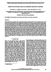
3. PRINCIPLE OF THE PROPOSED TECHNIQUE We developed an algorithm for the extraction of building walls using the proposed technique of independent rectification. This technique can extract the candidate line segments of a building’s footprint, which consists of the top horizontal edge of the building wall, using direction-limited edge matching in the object space. In this paper, we demonstrate the improvements made to the system, which in addition to the building wall includes extracting the rooftop and the groundlevel area beside the wall. The data-processing flowchart of the proposed technique is shown in Figure 1.
2. SUBJECT OF THIS RESEARCH 3.1 Generation using independent rectification
In the field of spatial-data modeling, a quality 3D city model requires not only the reality of expression, such as computer graphics, but also efficiency in data processing and accuracy in position measurement. The following issues are of concern in existing multi-image matching techniques.
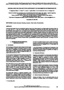
The conceptual diagram shown in Figure 2 indicates the method for the independent rectification image (IR image) generated by the independent rectification method (called IR method in this paper).
* Corresponding author.
339
International Archives of the Photogrammetry, Remote Sensing and Spatial Information Sciences, Volume XXXIX-B3, 2012 XXII ISPRS Congress, 25 August – 01 September 2012, Melbourne, Australia
Aerial Images (Multi-view images)
X Y Z
Independent Rectification
0 cos k sin k
Object-Space Searching
Direction-limited Edge Matching
Creation of Voxel Image
Voxel Image (Edge-Image)
Voxel Image (Image Matching)
Height-limited Edge Matching
Wall Matching
Candidate of Building Footprint
Wall
Horizontal Matching
Roof
cos k 0 - sin k - sin k 0 cos k 0 0 1
0 1 0 x y -f
sin 0 cos
k
k
Xk Yk Z k
(1)
Next, we define the horizontal virtual-base plane as the rotation angle of the camera position (= omega, phi, and kappa) as 0 and leave the other camera parameters, such as the camera-lens position and focal length of the projection central point, unchanged. The four corner points of the exterior-oriented image of the absolute object-coordinate system are projected onto the horizontal virtual-base plane according to the collinearity condition. In this way, we can obtain the four corner points that are converted to the photograph-coordinate system on the horizontal virtual-base plane. We can obtain IR images by performing a projective transformation of all the multi-view images onto the horizontal virtual-base plane using this method. After this projection conversion, the IR images satisfy the collinearity condition, and all pixels of the multiview images correspond to the original images.
Edge Direction
Edge-image Matching
0 - sin k cos k cos k sin k 0
Independently Rectified Images
Edge Extraction
Edge Image
1 0 0
3.2 Plane extraction by object-space searching In the existing technique, occlusion frequently occurs between multi-view images, and the feasibility of matching decreases on planes with heavily distorted images. Object-space searching is implemented to solve this problem. In the three processes shown below, multi-image matching is performed for planes of different directions. Rooftops, the ground, and walls are matched separately in the object space. Finally, we can try to extract the building shape based on plane matching.
Ground
Figure 1. Flowchart of Proposed Technique C1
3.2.1 Generation of Voxel Image: To perform plane matching in various directions in the object space, a voxel image is generated. The conceptual diagram is shown in Figure 3.
C2 Aerial Image #1
Z
Aerial Image #2
Object-Space Coordinates Roof Outline
Helmert transformation IR-image #1 IR-image #2
Z Y
Z
Camera Point
P
O
Feature Point
Y Y
X
Voxel-Images ( Px, Py, Pz, k, C )
Figure 2. Independent Rectification Method
(dx, dy, dz)
θ
(0, 0, 0)
First, to generate concrete multi-view images, the corresponding points are computed using coordinate transformation from the relative photographic-coordinate system to the absolute object-coordinate system, as shown in formula (1). Using formula (1), the four corner points of the exterior-oriented image in the relative photographic-coordinate system are transformed into four points in the absolute objectcoordinate system, accounting for the camera lens position and the camera rotation angle. In this formula, k indicates an image number (1, 2…N: N is the total number of multi-view images), f indicates the focal length of the aerial digital camera.
Absolute X coordinate system
X
Figure 3. Generation of a Voxel-Image The range of a voxel-image determines the size of the bounding box including line segment candidates on the roof footprint, which consists of the top edges of the wall. The width of the bounding box is determined by the length of the line segments of the roof footprint (the direction of X), the height is determined by the length between the rooftop and the ground (the direction of Z), and the depth is determined by searching
340
International Archives of the Photogrammetry, Remote Sensing and Spatial Information Sciences, Volume XXXIX-B3, 2012 XXII ISPRS Congress, 25 August – 01 September 2012, Melbourne, Australia
This process is repeated several times, and when the amount of compensation is below a set threshold, the wall surface searching calculation is complete. In this way, an exact wall position can be extracted.
the length as setting parameter (the direction of Y). Then, the relative coordinate system (X, Y, Z) of the lattice point is related to the absolute coordinate system (X, Y, Z) by the Helmert transformation. A voxel-image is generated using a projection that is the magnification conversion of an independent rectification image according to an altitude value obtained by resampling the lattice points of an absolute coordinate value in the object space.
4. EXPERIMENTAL PROCEDURE 4.1 Data Specification
3.2.2 Extraction of rooftop and ground by horizontal plane matching: The roof and ground are extracted using multi-image matching with the voxel-image of the object space using vertical direction searching, and the wall surface is extracted with the normal direction by searching horizontally. As shown in Figure 3, a voxel-image is divided into two segments on a line segment of the roof footprint with the depth direction of the wall. The rooftop and ground are searched in the vertical direction to each division domain by using horizontal plane matching with cross correlation to separately extract the height. In the case of ground searching, the occlusion obstructed more than half of the building in the multiview images. To address this, several images are sorted out for ground searching to determine the front and back of the wall based on the rotation direction of the 2D polygon’s vertex order on each independent rectification image. The 2D polygon’s vertex order is created by the projection transformation of the 3D polygon, which consists of the four corner points of the initial wall surface.
4.1.1 Sensor Specifications and Flight Parameters: The sensor specifications for the large format digital camera used to take aerial photographs are shown in Table 1, and the flight parameters to obtain multi-view images are shown in Table 2. Sensor Spec.
13,824 × 7,680 [Pixel]
CCD Size
165.9 × 92.2 [mm]
Pixel Size
12.0 [μm]
Flight Parameters
Parameters Values
Absolute altitude
Approximate 600 [m]
Over-lap Ratio
Approximate 66.7 [%]
Side-lap Ratio
Approximate 66.7 [%]
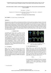
Number of Projects 2 [Projects] Table 2. Flight Parameters 4.1.2 Experimental Data: An example of the multi-view images used for the experiment is shown in Figure 5.
Matching Position Searching Direction Compensation Line
Initial-Roof Outline
Number of Pixels
Focal Length 120 [mm] Table 1. Sensor Specifications
3.2.3 Division matching for wall direction compensation: The initial wall that is obtained from the building’s footprint on an existing 2D map does not provide a good match to the actual direction of the wall. Our proposed method compensates by determining the precise position of the wall. The conceptual diagram is shown in Figure 4.
Z
Spec. Values
#11 #10
Y #9
X Divided Voxel-Image
Y
(Px, Py, Pz, k, C)
#7
#8
Matching in Voxel-Image
Y θ
#3
X
#5
#4
#6
X Regenerate of Voxel-Image
Figure 4. Compensation of Wall Direction
#2 Image #1
The proposed method can compensate for the wall direction by using the results of cross-correlation matching for each section. Cross-correlation matching is performed to detect matching positions in the depth direction of the wall in each section of the voxel-image, which is divided into lengthwise sections of the wall. The position and direction of the wall are estimated using the least-squares method from matching points of the correlation peak position, and a new voxel-image is generated.
Figure 5. Multi-View Images using Experiments The multi-view images are arranged as a complex image with the partial clipping of images (11 images: from numbers 1 to 11) of the same building. Our proposed technique can efficiently process multi-view images that are taken as a result of regular and irregular flight paths.
341
International Archives of the Photogrammetry, Remote Sensing and Spatial Information Sciences, Volume XXXIX-B3, 2012 XXII ISPRS Congress, 25 August – 01 September 2012, Melbourne, Australia
4.2 Experimental Procedure 4.2.1 Generation of Voxel-Images: The wall polygons, which are obtained by the extension method with the line segment of the building footprint created in generating the voxel-image, are superimposed on independent rectification images. Moreover, the result for interpolation processing of the wall surface images in a voxel-image will be illustrated. This shows that the generation of voxel-images is functioning correctly geometrically. In the experiment, the building polygon data of the existing map was used to specify the processing region.
#11 Image
#9
#7
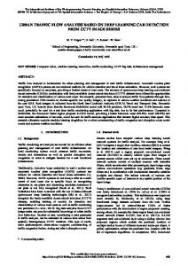
4.2.2 Extraction of rooftop and ground by horizontal plane matching: The division method of the voxel-image and the difference in the searching direction illustrate that the search for the rooftop and ground is possible. The variation in the pattern of the correlation coefficient in the image matching is illustrated in Figure 6, and the validity of the matching processing is proved.
#8
#5
#4
#3
#6
#2 #1
4.2.3 Division matching for wall direction compensation: Here wall division matching in the object space is carried out, and it verifies that wall matching, which also considers direction compensation, is performed appropriately. The position obtained by manual plotting is compared with the result of the proposed technique, and the position accuracy is evaluated quantitatively.
Figure 6. Generation of Voxel-Image
#11 5. RESULTS AND DISCUSSION
Image #10
5.1 Generation of Voxel-Image We performed a domain extension that made the baseline on the roof footprint line segment a part of the outline on the south. The partial voxel-image that is generated from the multi-view images is shown in Figure 6. The spatial vertical line is taken from the two-point vertex of a baseline of the roof footprint line segment, shown as the black solid line in the figure, toward the vanishing point. The square area at the top of the partial voxel-image, as shown by the red frame in the figure, is decided to surround this baseline. The independent rectification image can be calculated by the simultaneous magnification conversion of the image centering on the vanishing point with the multi-view images. The clipping image is created with the magnification conversion according to an altitude level (example: every 10 cm from 0 to 300 m), and it accumulates into the object space as a 3D partial voxelimage. According to this process, a five-dimensional partial voxel-image of the object-space coordinates XYZ (three dimensions), image numbers (one dimension), and a color band (one dimension) is generated.
#9
#7
#5
#4
#3
#8
#6
#2 #1 Figure 7. Interpolation in Local Voxel-Image of the images centering on the vanishing point with the multiview images. It is possible that the right projected conversion of the multi-view images enables extraction by the arbitrary slice plane in the object-space coordinate system.
Next, the interpolation of the wall surface image into a voxelimage is shown in Figure 7. This figure of the wall surface shows the cross-sectional image, which is the sliced partial voxel-image, at the initial position to obtain from the baseline. Image numbers 7 through 11 showing the upper part of the building were used to extract an undistorted image of the right wall. In the images of the lower half (numbers 1 to 6), shown in Figure 7, the right wall surface has become invisible because of the building’s own occlusion. In this process, we are able to extract the wall surface texture from the multi-view images using the character of the independent rectification images that can be calculated by the simultaneous magnification conversion
5.2 Extraction of rooftop and ground by horizontal plane matching Plane extraction by object-space searching is performed for the rooftop and the ground using the partial voxel-image of the nearby roof footprint line segment. The result is shown in Figure 8. The graph of the correlation value for the multi-image matching is illustrated in Figure 8 for the rooftop and ground. The blue frame in Figure 8 shows the results of the multi-image matching using all the partial voxel-images by the inside of the building, as explained in Figure 3.
342
International Archives of the Photogrammetry, Remote Sensing and Spatial Information Sciences, Volume XXXIX-B3, 2012 XXII ISPRS Congress, 25 August – 01 September 2012, Melbourne, Australia
Correlation value Altitude [m] Figure 8. Plane Matching in Object-Space Searching (Red: Wall, Blue: Roof, Green: Ground)
Figure 9. Result of Wall Matching (Left: Example of Direction Compensation / Right: Arch Wall)
343
International Archives of the Photogrammetry, Remote Sensing and Spatial Information Sciences, Volume XXXIX-B3, 2012 XXII ISPRS Congress, 25 August – 01 September 2012, Melbourne, Australia
”Initial Position” in Table 3 is the position accuracy of the roof outline by edge matching that indicates the measurement error is 1.37 m as a maximum value, and the RMSE is approximately 0.6–0.7 m. In contrast, ”Non Compensation” in Table 3 after wall matching is reduced to approximately a 0.2–0.3 m RMSE value. In addition, ”Non Compensation” is the result from wall matching without correction for the wall direction angle. The error value does not change for the wall direction angle; the error value of the horizontal position of the line vertex tended to decrease to the maximum value and the RMSE values. However, after wall matching in ”Non Compensation”, the RMSE value remains at 0.3 m. This reduced accuracy may be caused because the surface orientation of the roof outline that is used for wall matching does not match against the actual building wall. For this reason, compensation processing is performed by the division matching for the wall direction compensation to estimate the correct direction angle of wall. The RMSE value of the results obtained by the wall angle compensation, shown ”With Compensation” in Table 3, is less than 25 cm in both X and Y directions.
Next, the back-and-front judgment using a wall surface polygon is performed, and the image used for the wall surface matching on the front side is selected because of the larger size of that area on the independent rectification image. Then, the ground was matched using only the partial voxel-images of the building’s front-side. The green frame in the figure shows the result. Moreover, in the graph of the correlation value, the extracted roof-top was approximately 90 m, as a clear peak, and the ground was 10 m. As a result, the polygon of a rooftop and the ground are mapped correctly on all the independent rectifications. 5.3 Division matching for wall direction compensation The search results for the wall surface division matching are shown in Figure 9. The example of an incorrect extraction produced in the initial edge matching is shown on the left side of Figure 9. Thus, even when the correct roof footprint line segment was not obtained, the right wall surface position could be extracted by compensating for the wall direction. Although it was a rare example, the right side of Figure 9 shows an example of a building where the wall surface has become an arch. Here with each element in a division voxel-image, it appears that the right wall surface position can be extracted by applying a curved surface form. Next, the results of the wall matching compensation processing on the right wall’s direction angle for six buildings (each with four planes) is shown in Figure 10. Number of Walls
6. CONCLUSION In this study, we proposed and verified an independent rectification method that further improves the multi-image matching method. Here the problem was to extract the surface structure of a building using multi-view images obtained by an aerial survey. First, we generated the voxel-image by the IR method. Next, horizontal plane matching was conducted to extract the rooftop and ground surface. Further, the division matching of the wall is performed to compensate for the wall direction. Thus, we have developed a new method to extract the exact position of the rooftop, ground surface, and the walls around the initial line segment of the building’s footprint. In addition, we conducted experiments to evaluate the performance of the proposed IR method. Multi-image matching is performed using the voxel-images generated from the aerial images as multi-view images. The existing method of matching was complicated or made difficult by the occlusion of the building and the heavy distortion of the wall on the image. In contrast, the problem is addressed using the independently rectified images and the proposed matching method by which the object space can be searched in various directions. Future research includes automatic extraction to obtain the line segments of the building’s footprint when there is an inclined slanting roof, and automated structure recognition of complex building shapes.
Number of Walls
[deg] Before Compensation
After Compensation
Figure10. Results of the Wall Direction Histogram As a result, the root-mean-square error (RMSE) of the wall deflection angle that was at approximately 1.7 degrees at the maximum, in comparison with the manual plotting data, decreases to approximately 0.5 degrees when using the wall direction compensation processing. It proves that the wall is stabilized and an exact wall direction angle can be estimated by this technique. Moreover, to compensate for the wall direction angle, using the kurtosis peak of the correlation coefficient improves the results in the case of matching processing and contributes to improvements in the stable processing. The results of the target building using this wall matching technique and a comparison with the building wall corner points obtained by the manual plotting are shown in Table 3. Evaluation Items Initial Position (Max.) Initial Position (RMSE) Non Compensation (Max.) Non Compensation (RMSE) With Compensation (Max.) With Compensation (RMSE)
Error of Vertex dX [m] dY [m] 1.28 1.37 0.63 0.72 0.67 0.71 0.24 0.30 0.44 0.61 0.17 0.20
REFERENCES Christian Beder, 2004, A unified framework for the automatic matching of points and lines in multiple oriented images, Proc. 20th ISPRS Congress, Istanbul, Turkey. Martin Schluter, 1998, Multi-image matching in Object Space on the Basis of a General 3-D Surface Model Instead of common 2.5-D Surface Models and its Application for Urban Scenes. ISPRS Com. IV Symposium on GIS - between visions and applications.
Wall Dir. Error [deg] 1.73 0.67 1.73 0.67 0.69 0.27
Jianqing Zhang, J.Yong Zhang, Y. and Zuxun Zhang, Z., 2005, Multi-image matching for generation of DSM and true orthoimage, Proc. SPIE. Oda,K., Doihara,T., Shibasaki,R., 2004, Stereo Plane Matching Technique. Journal of the Japan Society of Photogrammetry and Remote Sensing, Vol.43, No.3, pp.13-21.
Table 3. Results of Wall Matching (vs. Manual Plotting)
344