Hindawi Publishing Corporation Journal of Engineering Volume 2016, Article ID 2385372, 10 pages http://dx.doi.org/10.1155/2016/2385372
Research Article Possibilities for Advanced Encoding Techniques at Signal Transmission in the Optical Transmission Medium Filip Hertík and Rastislav Róka Institute of Telecommunications, Slovak University of Technology in Bratislava, Ilkoviˇcova 3, 812 19 Bratislava, Slovakia Correspondence should be addressed to Rastislav R´oka;
[email protected] Received 25 November 2015; Accepted 13 March 2016 Academic Editor: A. S. Madhukumar ˇ ık and R. R´oka. This is an open access article distributed under the Creative Commons Attribution Copyright © 2016 F. Cert´ License, which permits unrestricted use, distribution, and reproduction in any medium, provided the original work is properly cited. This paper presents a possible simulation of negative effects in the optical transmission medium and an analysis for the utilization of different signal processing techniques at the optical signal transmission. An attention is focused on the high data rate signal transmission in the optical fiber influenced by linear and nonlinear environmental effects presented by the prepared simulation model. The analysis includes possible utilization of OOK, BPSK, DBPSK, BFSK, QPSK, DQPSK, 8PSK, and 16QAM modulation techniques together with RS, BCH, and LDPC encoding techniques for the signal transmission in the optical fiber. Moreover, the prepared simulation model is compared with real optical transmission systems. In the final part, a comparison of the selected modulation techniques with different encoding techniques and their implementation in real transmission systems is shown.
1. Introduction Nowadays, an interest in the signal transmission through optical fibers is rapidly increasing due to the transmission bandwidth. Creating new optical transmission paths can be time consuming and expensive [1–4]. Therefore, more effective approaches are appearing to satisfy increased customer requests. In both electric and optical domains, utilizing new advanced signal processing techniques can lead to increasing of the transmission capacity. Such solutions can be easily integrated. With increasing of modulation rates, negative influences on the transmitted optical signals are growing and so additional bit errors in information flows are emergent. Therefore, it is important to design and analyze a performance of advanced signal processing techniques utilized in the optical transmission medium with respect to its environmental influences. The simulation can determine transmission boundaries of each advanced signal processing technique for the designed optical system and allow comparing all possible solutions before their practical deployment. The simulation allows evaluating possible increasing of data rates and transmission ranges in deployed optical transmission systems using advanced signal processing techniques and
designing new optical transmission systems with advanced optical components and fibers. First, basic parameters of the optical fiber and principles of selected encoding techniques are introduced. In this paper, the simulation studies are restricted to the block codes. Convolutional codes with different rates and constraint lengths can later be considered along with the assumed modulation techniques. Then, a comparison of the prepared simulation model with real optical transmission systems measured by the Ciena system is presented. Moreover, a specific application of the optical transmission system with advanced optical signal processing techniques can also be represented in this case. A main attention of the contribution is focused on the analysis of different modulation and encoding techniques at the signal transmission in the optical transmission medium and their possible implementation in real transmission systems. From proposed, realized, and presented signal modulations, only some of them are considered for enhanced analysis, evaluation, and comparison purposes. In the final part, selected modulation and encoding techniques implemented on real transmission systems are analyzed for the high data rate signal transmissions.
2
Journal of Engineering
1.1. Characteristics of the Optical Fiber. Each optical fiber represents a transmission system, which is frequency dependent. A pulse propagation inside this transmission system can be described by the nonlinear Schr¨odinger equation (NLSE), which is derivate from Maxwell’s equations. From the NLSE equation, we can express effects in optical fibers that are classified as [5, 6] (a) linear effects, which are wavelength dependent, (b) nonlinear effects, which are intensity (power) dependent. Linear Effects. Major impairments of optical signals transmitted via the optical fiber environment are mainly caused by linear effects, the dispersion and the attenuation. The attenuation limits a power of optical signals and represents transmission losses. Nowadays, optical transmission systems are able to minimize impact of the attenuation by deploying all-optical amplifiers. Another source of the linear effect represents the dispersion causing broadening of optical pulses in time and signal phase shifting at the fiber end. There are three main dispersion types [5–8]: (i) The modal dispersion caused by the different propagation velocity of optical modes propagating in multimode fibers. (ii) The chromatic dispersion caused by the different propagation velocity of wavelengths generated in laser sources propagating in the optical fiber. It consists of material, profile, and waveguide dispersions. (iii) The polarization mode dispersion caused by the birefringence effect due to a nonsymmetry and imperfections of optical fibers. Nonlinear Effects. These effects play an important role at the long haul optical signal transmission. Nonlinear effects can be classified as follows: (i) Kerr nonlinearities are self-induced effects, where the phase velocity of the pulse depends on the pulse’s own intensity. The Kerr effect describes a change in the fiber refractive index due to electrical perturbations. Due to the Kerr effect, following effects are possible to describe: (a) Self-phase modulation (SPM) is an effect that changes the refractive index of the transmission medium caused by the pulse intensity [9, 10]. (b) Four-wave mixing (FWM) is an effect where the fourth wave can be arisen by mixing of three optical waves and this one can appear in the same wavelength as one of mixed waves [9]. (c) Cross-phase effect (XPM) is an effect that causes a spectral broadening where the optical pulse can change the phase of another pulse with different wavelengths [9–11]. (ii) Scattering nonlinearities occur due to a photon inelastic scattering to lower energy photons. The pulse
energy is transferred to another wave with a different wavelength. Two such effects appear in the optical fiber: (a) Stimulated Brillouin scattering (SBS) and stimulated Raman scattering (SRS) are effects that change a variance of light wave into different waves when the intensity reaches a certain threshold [9–11]. 1.2. Principles of Selected Encoding Techniques. Forward error correction (FEC) techniques represent a system where additional data are inserted into a data message so that it can be recovered by a receiver even when a number of errors due to transmission is emergent. These FEC codes are widely used in systems where a data retransmission is not an option such as broadcasting and high haul optical transmission systems [12, 13]. FEC codes are usually divided into convolutional and block codes: (i) Convolutional codes are processed on a bit-by-bit basis. (ii) Block codes are processed on a block-by-block basis. Convolutional codes are based on the encoding signal with a final impulse response. This type of coding does not require division of bits into the blocks. The convolution codes may be decoded using the Viterbi algorithm, which is a method of decoding with maximum reliability. This method is based on finding the most appropriate way forward through the possible states of transition. The complexity of the Viterbi algorithm increases with the number of states in decoding. Therefore, it is advisable to use codes that use a small amount of redundancy. Convolutional codes have lower resistance against noise than the linear block codes and not using the minimal trellis like linear blocks [13, 14]. For analysis, block codes, especially cyclic block codes, are considered. Cyclic block codes are widely used in data communication because their structure makes encoder and decoder circuitry simple. Cyclic block codes are defined as the cyclic (𝑛, 𝑘) code if 𝐶 is a linear code of the length 𝑛 over a finite field and if any cyclic shift of a codeword is also a codeword as shown in 𝑐0 , 𝑐1 , . . . , 𝑐𝑛−1 ∈ 𝐶 ⇒ 𝑐𝑛−1 , 𝑐0 , 𝑐1 , . . . , 𝑐𝑛−2 ∈ 𝐶.
(1)
The information data with the length 𝑘 are coded with the polynomial 𝑔(𝑥) using (1). Consider 𝑐 (𝑥) = 𝑖 (𝑥) 𝑔 (𝑥) ,
(2)
where 𝑐(𝑥) represents the polynomial of degree (𝑛 − 1), 𝑖(𝑥) is the information polynomial of degree (𝑘 − 1), and the generator polynomial 𝑔(𝑥) must be of degree (𝑛 − 𝑘). The Reed-Solomon (RS) codes that belong to cyclic block codes are widely used in many communication fields [13, 14]. The RS codes are related to BCH codes and can be defined as a primitive BCH code of the length 𝑛, where 𝑛 = 𝑞 − 1 = 2𝑠 − 1 over GF (𝑞) = GF (2𝑠 ) .
(3)
Journal of Engineering
3
RS codes are specified as RS(𝑛, 𝑘) or RS(𝑛, 𝑘, 𝑑), where 𝑛 represent the code length, 𝑘 represents the information length, and 𝑑 is the Hamming distance. Let 𝑡 be a number of errors that can be corrected; then correction (𝑡) or detection (2𝑡) abilities are specified for the code. There exist two encoding types for RS codes:
Sample_time
×
Multiple
Binary input RS encoder Binary input RS encoder
1 Gaussian Out Gaussian filter
[Orig] Goto
(i) Nonsystematic. (ii) Systematic. The decoding for RS codes is based on syndrome equations: 𝑡
𝑠𝑘 = ∑𝑌𝑖 𝑋𝑖𝑘 ; 𝑘 = 0, 1, . . . , 2𝑡 − 1,
Bernoulli binary Bernoulli binary generator
(4)
𝑖=1
where 𝑋𝑖 is the locator 𝑖th error and 𝑌𝑖 represents its value (detection of location and value). More information about RS encoding techniques can be found in [13]. The Bose Chaudhuri Hocquenghem (BCH) code is a cyclic polynomial code over a finite field with chosen polynomial generator. BCH codes are 𝑡-error correcting codes defined over finite fields GF(𝑞), where 2𝑡 + 1 < 𝑞. The advantage of BCH codes is using syndrome to decode errors in which there exist good decoding algorithms that correct multiple errors [14]. The generating of a binary BCH code over an extension field GF(𝑞𝑚 ) is easy to construct. The polynomial generator 𝑔(𝑥) is needed to obtain a cyclic code [12–16]. For any integer 𝑚 ≥ 3 and 𝑡 < 2𝑚 − 1, there exists a primitive BCH code with parameters 𝑛 = 2𝑚 − 1, 𝑛 − 𝑘 ≤ 𝑚 ⋅ 𝑡, and 𝑑min ≤ 2𝑡 + 1. The generator polynomial 𝑔(𝑥) of 𝑡-error correcting primitive BCH codes of the length 2𝑚 − 1 is given by 𝑔 (𝑥) = LCM {𝑚1 (𝑥) , 𝑚2 (𝑥) , . . . , 𝑚2𝑡−1 (𝑥) , 𝑚2𝑡 (𝑥)} , (5)
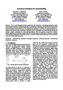
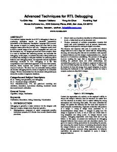
where LCM represents the Least Common Multiple. Then the code is generated using (2). BCH codes are decoded with various algorithm based on calculation of syndromes values for the received codeword. Low Density Parity Check (LDPC) codes belong to linear encoding techniques that can transmit data close to the Shannon theorem (the channel capacity). The main disadvantage of the LDPC code is the time consumption of the code algorithm, which often limits its utilization in high data rate optical transmission systems. However, it is possible to encode more low data rate signals and then merge them into one high data rate signal. The high data rate signal can be transmitted via the optical transmission system. The LDPC coding is defined by the LDPC 𝐻 matrix. Assuming the length of information bits K, the length of encoded bits 𝑁, and the average weigh column 𝑤 > 2 (weight vectors represent the sum of nonzero components of the vector), then 𝑀 = (𝑁 − 𝐾) is the sum of the parity check in code. The LDPC matrix 𝐻 is composed of 𝑀 rows and 𝑁 columns. The generation matrix 𝐺 is necessary to encode coding sequence [14, 15]. Prepared block schemes of mentioned encoding techniques in the simulation model are shown in Figures 1 and 2. Figure 3 shows the schematic block diagram of LDPC source
Figure 1: The block scheme for the signal generation with RS and BCH encoding techniques.
signal. Blocks are initiated using a Bernoulli generator that generates random binary bits representation of the information signal. The signal is then coded with an adequate encoding technique. The output signal is filtered with a Gaussian filter for representation of the real signal. The LDPC block is created by using 10 Bernoulli generators, each encoded with the LDPC code and merged into the high data rate signal [16, 17].
2. The Simulation of the Optical Transmission System The prepared simulation model comes out from the simulation model for optical communications introduced in [18– 20]. A modeling is performed in the Matlab Simulink 2014 programming environment. The simulation model presents an influence of linear and nonlinear effects present in the optical transmission medium at the signal transmission. The general schematic block diagram is shown in Figure 4. To verify a reliability and exactness of the simulation model, authors realized a comparison of two optical transmission paths measured in cooperation with the Orange Slovakia company. The optical path 1 consists of the 59.2 km standard SM (ITU-T G.652) fiber with the 10 Gbit/s noncoherent OOK modulated signal using 80 WDM channels. The optical path 2 consists of 170.7 km standard SM (ITU-T G.652) fiber with the 10 Gbit/s noncoherent OOK modulated signal using 80 WDM channels. Transmitted signals are examined with the 193.4 THz frequency. Both paths are utilizing EDFA amplifiers at the optical fiber end, while the optical path 2 is furthermore using additional 3 EDFA amplifiers every 40 km. Simulation models for the optical path 1 and optical path 2 are shown in Figures 5 and 6, respectively. For describing information signal transmission, a bit error rate (BER) parameter can be calculated. The BER calculation for each simulation model is done by comparing input and output bits. For both optical paths, simulation results show the BER parameter higher than 10−12 , satisfying common transmission conditions. For both simulation models, the Reed-Solomon code RS(255, 239) is utilized to enhance the system BER parameter. For both optical paths, presented simulated and measured transmission parameters (Tables 1 and 2) include besides other received optical power level values for calculations related to the attenuation. As can be seen, parameters are very similar, at which the simulation is characterized by worse ones. Therefore, if the optical simulation is passed, then the real system would be properly and correctly operating.
4
Journal of Engineering
Bernoulli binary Sample_time 7
Sample_time
Sample_time 1
Bernoulli binary generator 7
Bernoulli binary Bernoulli binary generator
Bernoulli binary Bernoulli binary generator 1
× Multiple 7
× Multiple
× Multiple 1
LDPC encoder Sample_time 8 LDPC encoder 7
Bernoulli binary Bernoulli binary generator 8
× Multiple 8
LDPC encoder LDPC encoder 8
LDPC encoder LDPC encoder
LDPC encoder LDPC encoder 1
In1 In2 In3
Sample_time 2
Bernoulli binary Bernoulli binary generator 2
× Multiple 2
LDPC encoder
In4
LDPC encoder 2
In6
In5
Out Merge
In7
Sample_time 3
Sample_time 4
Sample_time 5
Sample_time 6
Bernoulli binary Bernoulli binary generator 3
Bernoulli binary Bernoulli binary generator 4
Bernoulli binary
× Multiple 3
× Multiple 4
×
Bernoulli binary generator 5
Multiple 5
Bernoulli binary Bernoulli binary generator 6
× Multiple 6
Gaussian
1 Out
Gaussian filter
In8 LDPC encoder
In9 In10 10 ∗ 1 Gbit/s to 10 Gbit/s
LDPC encoder 3
LDPC encoder LDPC encoder 4
LDPC encoder LDPC encoder 5
LDPC encoder
Sample_time 9
LDPC encoder 6
Bernoulli binary Bernoulli binary generator 9
× Multiple 9
LDPC encoder LDPC encoder 9
Figure 2: The block scheme for the signal generation with the LDPC encoding technique.
Table 1: The optical path 1 transmission parameters. Parameters Rx power (dBm) OSNR (dB) PMD (ps) SPM (dB) XPM (dB) FWM (dB) 𝑄 BER
Measured −13.2 25.9 1.06 0.87 −57.59 N/A 7.99 >10−15
Simulated −13.4 24.3 1.25 1.22 −60.5 −124.3 8.1 >10−12
3. The Analysis of Selected Modulation and Encoding Techniques The first modulation technique used for real optical transmission systems was the two-level amplitude modulation OOK with the direct detection. This system is characterized by transmission rates from 1 Gbit/s and its limitation is represented by the 10 Gbit/s rate over optical single mode fibers with the 50 km line length. Nowadays, OOK systems
Table 2: The optical path 2 transmission parameters. Parameters Rx power (dBm) OSNR (dB) PMD (ps) SPM (dB) XPM (dB) FWM (dB) 𝑄 BER
Measured −13.69 21.07 1.74 1.03 −42.02 N/A 6.27 >10−15
Simulated −12.3 20.9 1.83 1.1 −40.5 −112 6.2 >10−12
are deployed with coherent receivers that can increase the system range depending on the receiver sensitivity and the transmitters’ generated noise. Coherent systems highly improve transmission characteristics, but their implementation is expensive due to security mechanisms for phase and polarization detecting. Another possible improvement for coherent systems is represented by using the Duobinary modulation. This leads to a modification in the electrical domain that is less costly than in case of exchange optical
Journal of Engineering
5
Bernoulli generator rectangular impulse
LDPC coding n= i+k 1 Gbit/s
Bernoulli generator rectangular impulse
LDPC coding n= i+k 1 Gbit/s
Bernoulli generator rectangular impulse
LDPC coding n= i+k 1 Gbit/s
Bernoulli generator rectangular impulse
LDPC coding n= i+k 1 Gbit/s
Bernoulli generator rectangular impulse
LDPC coding n= i+k 1 Gbit/s
Bernoulli generator rectangular impulse
LDPC coding n= i+k 1 Gbit/s
Bernoulli generator rectangular impulse
LDPC coding n= i+k 1 Gbit/s
Bernoulli generator rectangular impulse
LDPC coding n= i+k 1 Gbit/s
Bernoulli generator rectangular impulse
LDPC coding n= i+k 1 Gbit/s
Bernoulli generator rectangular impulse
LDPC coding n= i+k 1 Gbit/s
1 Gbit/s 1 Gbit/s 1 Gbit/s 1 Gbit/s 1 0 0
1 Gbit/s 1 Gbit/s
Merge block
1 1 1 0 1 0 1
1 Gbit/s 1 Gbit/s 1 Gbit/s
Sample generator
1 Gbit/s
Gauss filter 10 Gbit/s 1001110101 10 Gbit/s
1/10
1 Gbit/s
Figure 3: The schematic block diagram for the signal generation with the LDPC encoding technique.
System signal source Electric data signal
Wavelength division multiplex
Mach-Zehnder modulator
Continuous optical wave
2
Laser source Phase and amplitude detection
Erbium doped fiber
Electric data signal
Local oscillator
.. .
.. . N
Optical fiber
Signal with different wavelength System signal source
Circulator
1
Signal with different wavelength System signal source
Chromatic and polarization mode dispersion [time broadening, signal phase shift]
Self-phase and Four-wave mixing [intensity noise from cross-phase modulation [phase noise and neighbour channels on signal frequency shift different wavelength] due to signal intensity]
Stimulated Brillouin and Raman scattering, attenuation [intensity noise from neighbour channels and decreasing signal intensity]
Figure 4: The schematic block diagram for the optical transmission system.
components. For given modulation, the Monte Carlo algorithm can be used because it allows a measuring of the BER parameter. The simulation model uses the standard SM (ITU-T G.656) optical fiber. The comparison of transmission characteristics for coherent OOK and Duobinary systems is shown in Figure 7. Possible solution can be represented by coherent systems with phase and frequency modulation techniques, which are
represented by BPSK, DBPSK, and BFSK. These modulation techniques achieve similar transmission characteristics (shown in Figure 8), where the BPSK achieves better results, about 0.1 dB compared to the DBPSK and about 3 dB compared to the FSK. Higher modulation formats can be further used to increase signal transmission rates in the optical system [21– 25]. Such modulation techniques have a lower tolerance to
6
Journal of Engineering
In1
Out1
Out1
In1
In2
Data signal
In2 MZM
Out1
In1
Out1
In3
Out1
SMF—59.2 km
WDM
In2 Demodulator
CW
Out1 Cooperating channels
Out1 EDFA
Figure 5: The simulation model for the optical path 1.
Out1
In1 Out1
Data signal
In2
In2 MZM
Out1
In1 Out1
In3 WDM
In1
Out1
SMF—44.2 km
In2
Out1
Erbium doped fiber
CW In1
In2
Out1
Out1
Out1 SMF—42.5 km
Erbium doped fiber 1
Cooperating channels In1
Out1
Out1
SMF—43.3 km
EDFA
In1
In2
Erbium doped fiber 2
Out1
SMF—40.7 km
Out1
In2
Out1
Erbium doped fiber 3
In2 Demodulator
Figure 6: The simulation model for the optical path 2.
the optical signal-to-noise ratio (OSNR); and, therefore, it is necessary to analyze the BER parameter depending on the OSNR. Figure 9 shows transmission characteristics for highlevel modulation formats. QPSK and DQPSK keying exhibit similar resistance to noise as BPSK and DBPSK keying. In this case, the transmission rate would be increased twice and if the polarization modulation (PDM) is used, then the 40 Gbit/s transmission rate can be reached. This solution requires the deployment of MZM modulators and the PDM modulator. For 8PSK and 16QAM modulations, the noise resistance is decreasing around 2 dB that, in some systems, will lead to
higher bit error rates caused by laser noise, amplifier noise, and/or nonlinear effects of the optical transmission medium. For improving transmission rates of modulation formats, different encoding techniques can be used [26, 27]. A complete scheme of the prepared optical transmission system is shown in Figure 10, where the total optical fiber length is extended to 320 km. After theoretical analysis, the following codes RS(255, 239), BCH(255, 231), and LDPC(960, 480) were selected. The RS and BCH codes are capable of encoding data quickly up to 10 Gbit/s; however, the LDPC codes require more
Journal of Engineering
7
100 10−1 10−2 BER
10−3 10−4 10−5 10−6 10−7 10−8
0
2
4
6
8 10 Eb /N0 (dB)
12
14
16
18
OOK NRZ Duobinary
Figure 7: BER transmission characteristics for OOK keying and Duobinary modulation.
100
4. The Implementation of Modulation and Encoding Techniques
10−1
BER
10
−2
10−3 10−4 10−5 10−6 10−7 10−8
0
2
4
6
8
10
12
14
16
18
Eb /N0 (dB)
DBPSK BPSK BFSK
Figure 8: BER transmission characteristics for BPSK, DBPSK, and BFSK keying.
100 10−1 10−2 BER
10−3 10−4 10−5 10−6 10−7 10−8
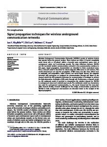
time to encode data. Therefore, 10 data streams are encoded separately and afterwards multiplexed into one data stream (shown in Figure 2). For analyzing and simulating, only binary modulation formats are used. A comparison of binary modulation techniques (noncoherent OOK, BPSK, and DBPSK) combined with encoding techniques (RS, BCH, and LDPC) is shown in Figure 11. Encoding techniques can increase the system range from 50 km up to 160 km depending on appropriate code. Better transmission characteristics are achievable through coherent phase modulations BPSK and DBPSK, where limitations are between 80 and 100 km. The BCH and RS codes increase the range of these systems up to 160 km and this system range can be increased up to 230 km by using the LDPC code. The LDPC code is more than 50% efficient compared to BCH and RS codes; however, such a system needs encoding individual data signals with lower transmission rates than the total system transmission rate. Therefore, it is more effective to use the LDPC code in metropolitan networks, where a time multiplexing is used.
0
2
4
DQPSK 8PSK
6
8 10 Eb /N0 (dB)
12
14
16
18
QPSK 16QAM
Figure 9: BER transmission characteristics for QPSK, DQPSK, 8PSK, and 16QAM keying.
Selected modulation and encoding techniques are implemented on the optical transmission system with the standard SM fiber (ITU-T G652), where a data signal with the 10 Gbit/s transmission rate and 80 WDM channels is transmitted. Individual transmitters are designed using the MZM modulator, where a continuous wave generated in the CW-DFB laser is modulated with a data signal generated by the Bernoulli generator. The CW-DFB laser generates a continuous wave with 1 mW power and embeds the 4 dB amplitude noise. It is considered that a phase noise is suppressed. The analyzed signal is transmitted with the 193.4 THz optical frequency and the resulting OSNR is 30 dB. For increasing the optical transmission path range, EDFA amplifiers are used every 40 km for amplifying the transmitted signal, where a noise figure NF is equal to 4 dB. The optical fiber with a negative CD is placed before a receiver to compensate the CD effect in the system. The received signal is detected by a coherent detector whose sensitivity is around −17 dBm. Based on the previous analysis, a hard decision scheme with the LDPC(960, 480) code is selected for implementation. First, binary modulation techniques can be considered, where the OOK has the worst transmission characteristics; and therefore, the transmission system range is limited to 230 km. The analyzed BPSK and BFSK modulations achieve similar transmission characteristics, where both systems are capable of having a signal transmission over the 300 km line length with the 10 Gbit/s transmission rate. It is optional to use these modulations to achieve the longest transmission system range. For increasing transmission rates of these modulations, it is possible to use a combination with the PDM (PDM-BPSK and PDM-BFSK), where the transmission rate of these systems will be higher twice (20 Gbit/s). For achieving higher transmission rates, it is necessary to use multilevel modulation formats. The QPSK signal range is around 300 km, where a transmission rate compared with
8
Journal of Engineering
Out1 Data signal
In1 Out1
In2 MZM
Samsung SM NZD-SF 80 km length
In1 In2 In3
Out1
Out1
Out
In
WDM
Out
In
In
PMD
CHD
Out FWM
In2
Out1
SPM & XPM
In1
Out1
In2
Out1
Erbium doped fiber
SRS & SBS & attenuation
Samsung SM NZD-SF 80 km length
CW Out
In
Out1
Out
In
CHD1
Out
In
PMD1
FWM1
Cooperating channels
In2
Out1
SPM & XPM1
In1
Out1
In2
SRS & SBS & attenuation 1
Out1
Erbium doped fiber 1
Samsung SM NZD-SF 80 km length
Out1
Out
In
In
CHD2
EDFA
Out
Out
In
PMD2
FWM2
In2
Out1
SPM & XPM2
In1
In2
Out1
SRS & SBS & attenuation 2
Out1
Erbium doped fiber 2
Samsung SM NZD-SF 80 km length Out
In
CHD3
Out
In PMD3
Out
In FWM3
In2
Out1
SPM & XPM3
In1
Out1
In2
SRS & SBS & attenuation 3
Out1
In2
Erbium doped fiber 3
Demodulator
Figure 10: The block scheme for analysis of the selected modulation and encoding techniques. Table 3: Comparison of selected modulation techniques implemented for the optical transmission system. Modulation techniques
BER [ ] OSNR [dB] BER [ ] OSNR [dB] BER [ ] OSNR [dB] BER [ ] OSNR [dB] BER [ ] OSNR [dB] BER [ ] OSNR [dB] BER [ ] OSNR [dB]
OOK BPSK DBPSK BFSK QPSK 8PSK
BER
16QAM
×10−3 0 1 2 3 4 5 6 7 8 9 10 0
Parameters
40 10−12 25 10−12 27 10−12 27 10−12 28 10−12 27 10−12 27 10−12 27
80 10−12 19 10−12 24 10−12 24 10−12 26 10−12 24 10−12 23 10−12 22
Calculated BER
50
100
150 200 Length (km)
OOK BPSK DBPSK OOK-RS (255, 239) BPSK-RS (255, 239) DBPSK-RS (255, 239)
250
300
350
OOK-BCH (255, 231) BPSK-BCH (255, 231) DBPSK-BCH (255, 231) OOK-LDPC (960, 480) BPSK-LDPC (960, 480) DBPSK-LDPC (960, 480)
Figure 11: Comparison of binary modulation techniques combined with encoding techniques.
120 10−12 14 10−12 20 10−12 20 10−12 24 10−12 20 10−12 19 10−12 17
Fiber length [km] 160 200 10−9 10−2 7 2 −12 10 10−12 17 15 10−12 10−12 17 15 10−12 10−12 21 18 −12 10 10−12 17 15 10−12 10−10 14 9 10−12 10−9 12 7
240 10−1 1 10−12 11 10−12 11 10−12 16 10−12 11 10−6 6 10−3 2
280 10−1 1 10−11 8 10−10 8 10−11 13 10−11 8 10−3 2 10−1 2
320 10−1 1 10−9 5 10−8 5 10−9 10 10−9 5 10−2 1 10−1 1
binary modulations is twice higher. Using a combination with the PDM, the result transmission rate achieves 40 Gbit/s. The maximum range of 8PSK and 16QAM systems is around 200 km. The decreased range of these systems is due to amplifier noises and nonlinear effects in the optical environment. However, these systems using the PDM have transmission rates 60 Gbit/s (PDM-8PSK) and 80 Gbit/s (PDM-16QAM) per channel. The analysis shows that the range limitation is mainly caused by amplifier noises and nonlinear effects that are accumulating. For increasing the system range of multilevel modulation formats, the use of encoding techniques such as the LDPC(960, 480) code is optional. For further improvement of transmission characteristics, optical amplifiers with a low noise figure, advanced detectors, and soft encoding schemes can be used. However, these components rapidly increase the system cost and particular financial analysis for the system effectiveness is necessary. Output transmission characteristics for each modulation technique are shown in Table 3.
Journal of Engineering
5. Conclusion This contribution analyzes a possible utilization of selected modulation and advanced encoding techniques at high data rate signal transmission in optical transmission medium. At first, the prepared simulation model for optical transmission systems with real transmission systems is compared. Next, a performance analysis of different binary and multilevel modulation techniques in combination with RS, BCH, and LDPC codes utilized in optical transmission systems is presented. The simulation results show the limitation of binary modulation techniques and their possible improvement using FEC codes. The LDPC code can improve a system’s performance for all modulation schemes. Finally, a prepared optical system with real parameters is enhanced using the LDPC code and selected modulation and encoding techniques are analyzed for their practical implementation. In future analyses, convolutional or turbo codes with different rates and constraint length can be considered. Moreover, other recent modulation techniques in possible combinations with encoding techniques are analyzed. Besides, a utilization of solitons with available optical signal processing techniques is a very interesting area.
Disclosure This work is a part of research activities conducted at Slovak University of Technology Bratislava, Faculty of Electrical Engineering and Information Technology, Institute of Telecommunications, within the scope of Projects VEGA no. 1/0174/16 “Advanced Algorithms and Methods for New Generation Optical Networks for the IMS and NGN Converged Infrastructure” and KEGA no. 007STU-4/2016 “Progressive Educational Methods in the Field of Telecommunications Multiservice Networks.”
Competing Interests The authors declare that they have no competing interests.
References [1] K. Fukuchi, T. Kasamatsu, M. Morie et al., “10.92-Tb/s (273×40Gb/s) triple-band/ultra-dense WDM optical-repeatered transmission experiment,” in Proceedings of the Optical Fiber Communication Conference (OFC ’01), Paper PD24, 2001. [2] Z. Jia, J. Yu, H.-C. Chien, Z. Dong, and D. Di Huo, “Field transmission of 100 G and beyond: multiple baud rates and mixed line rates using nyquist-WDM technology,” Journal of Lightwave Technology, vol. 30, no. 24, Article ID 6235964, pp. 3793–3804, 2012. [3] H. Rohde, E. Gottwald, A. Teixeira et al., “Coherent ultra dense WDM technology for next generation optical metro and access networks,” Journal of Lightwave Technology, vol. 32, no. 10, pp. 2041–2052, 2014. [4] H. Taga, “Long distance transmission experiments using the WDM technology,” Journal of Lightwave Technology, vol. 14, no. 6, pp. 1287–1298, 1996. [5] B. E. A. Saleh and M. C. Teich, Fundamentals of Photonics, Wiley-Interscience, 1991.
9 [6] L. N. Binh, Optical Fiber Communication Systems, CRC Press, New York, NY, USA, 2010. [7] G. Keiser, Optical Fiber Communications, John Wiley & Sons, New York, NY, USA, 2003. [8] Z. Jamaludin, A. F. Abas, A. S. M. Noor, and M. K. Abfullah, “Issues on polarization mode dispersion (PMD) for high speed fiber optics transmission,” Suranaree Journal of Science and Technology, vol. 12, no. 2, pp. 98–106, 2005. [9] S. P. Singh and N. Singh, “Nonlinear effects in optical fibers: origin, management and applications,” Progress in Electromagnetics Research, vol. 73, pp. 249–275, 2007. [10] E. Iannone, F. Matera, A. Mecozzi, and M. Settembre, Nonlinear Optical Communication Networks, TK5103.59.N66, John Wiley & Sons, New York, NY, USA, 1998. [11] D. Cotter, “Nonlinearity in optical fibre communications,” in Nonlinear Optics in Signal Processing, R. W. Eason and A. Miller, Eds., vol. 49 of Engineering Aspects of Lasers Series, Springer, Amsterdam, Netherlands, 1993. [12] R. Hill, A First Course in Coding Theory, Clarendon Press, Oxford, UK, 1980. [13] W. Trappe and L. C. Washington, Introduction to Cryptography with Coding Theory, Pearson Prentice Hall, New Jersey, NJ, USA, 2006. [14] J. H. van Lint, Introduction to Coding Theory, Springer, Berlin, Germany, 1999. [15] M. Bossert, Channel Coding for Telecommunications, John Wiley & Sons, New York, NY, USA, 1999. ˇ ık, “Utilization of encoding techniques at the signal trans[16] F. Cert´ mission in the optical fiber,” in Advances in Signal Processing, vol. 3, no. 2, pp. 17–24, 2015. ˇ ık, “The analysis of different encoding and modulation [17] F. Cert´ techniques at the signal transmission in the optical medium,” in Proceedings of the 37th International Symposium on the Application of Computers and Operations Research in the Mineral Industry (APCOM ’15), pp. 978–80, STU Publishing House, Bratislava, Slovakia. [18] R. R´oka, “Fixed transmission media,” in Technology and Engineering Applications of Simulink, S. Chakravarty, Ed., pp. 41–68, InTech, Rijeka, Croatia, 2012. ˇ ık, “Simulation tools for broadband passive [19] R. R´oka and F. Cert´ optical networks,” in Simulation Technologies in Networking and Communications: Selecting the Best Tool for the Test, CRC Press, Boca Raton, Fla, USA, 2014. [20] R. R´oka, “The environment of fixed transmission media and their negative influences in the simulation,” International Journal of Mathematics and Computers in Simulation, vol. 9, pp. 190– 205, 2015. [21] R. Essiambre, G. Kramer, P. J. Winzer, G. J. Foschini, and B. Goebel, “Capacity limits of optical fiber networks,” Journal of Lightwave Technology, vol. 28, no. 4, pp. 662–701, 2010. [22] P. J. Winzer and R. J. Essiambre, “Advanced optical modulation formats,” Proceedings of the IEEE, vol. 94, no. 5, pp. 952–985, 2006. [23] M. I. Olmedo, T. Zuo, J. B. Jensen et al., “Multiband carrierless amplitude phase modulation for high capacity optical data links,” Journal of Lightwave Technology, vol. 32, no. 4, pp. 798– 804, 2014. [24] T. Rahman, D. Rafigue, A. Napoli et al., “Ultralong haul 1.28-Tb/ s PM-16QAM WDM transmission employing hybrid amplification,” Journal of Lightwave Technology, vol. 33, no. 9, pp. 1794– 1804, 2015.
10 [25] S. Chandrasekhar and X. Liu, “Experimental investigation on the performance of closely spaced multi-carrier PDM-QPSK with digital coherent detection,” Optics Express, vol. 17, no. 24, pp. 21350–21361, 2009. [26] I. B. Djordjevic, “Generalized LDPC codes and turbo-product codes with reed-muller component codes,” in Proceedings of the 8th International Conference on Telecommunications in Modern Satellite, Cable and Broadcasting Services (TELSIKS ’07), pp. 127–134, Niˇs, Serbia, September 2007. [27] D. Ouchi, K. Kubo, T. Mizuochi et al., “A fully integrated block turbo code FEC for 10 Gb/s optical communication systems,” in Proceedings of the Optical Fiber Communication (OFC ’06), Anaheim, Calif, USA, March 2006.
Journal of Engineering
International Journal of
Rotating Machinery
Engineering Journal of
Hindawi Publishing Corporation http://www.hindawi.com
Volume 2014
The Scientific World Journal Hindawi Publishing Corporation http://www.hindawi.com
Volume 2014
International Journal of
Distributed Sensor Networks
Journal of
Sensors Hindawi Publishing Corporation http://www.hindawi.com
Volume 2014
Hindawi Publishing Corporation http://www.hindawi.com
Volume 2014
Hindawi Publishing Corporation http://www.hindawi.com
Volume 2014
Journal of
Control Science and Engineering
Advances in
Civil Engineering Hindawi Publishing Corporation http://www.hindawi.com
Hindawi Publishing Corporation http://www.hindawi.com
Volume 2014
Volume 2014
Submit your manuscripts at http://www.hindawi.com Journal of
Journal of
Electrical and Computer Engineering
Robotics Hindawi Publishing Corporation http://www.hindawi.com
Hindawi Publishing Corporation http://www.hindawi.com
Volume 2014
Volume 2014
VLSI Design Advances in OptoElectronics
International Journal of
Navigation and Observation Hindawi Publishing Corporation http://www.hindawi.com
Volume 2014
Hindawi Publishing Corporation http://www.hindawi.com
Hindawi Publishing Corporation http://www.hindawi.com
Chemical Engineering Hindawi Publishing Corporation http://www.hindawi.com
Volume 2014
Volume 2014
Active and Passive Electronic Components
Antennas and Propagation Hindawi Publishing Corporation http://www.hindawi.com
Aerospace Engineering
Hindawi Publishing Corporation http://www.hindawi.com
Volume 2014
Hindawi Publishing Corporation http://www.hindawi.com
Volume 2014
Volume 2014
International Journal of
International Journal of
International Journal of
Modelling & Simulation in Engineering
Volume 2014
Hindawi Publishing Corporation http://www.hindawi.com
Volume 2014
Shock and Vibration Hindawi Publishing Corporation http://www.hindawi.com
Volume 2014
Advances in
Acoustics and Vibration Hindawi Publishing Corporation http://www.hindawi.com
Volume 2014