May 5, 2001 - This paper presents a new topology of a SEPIC converter used in power factor correction circuits. The conventional SEPIC converter was ...
24th International Spring Seminar on Electronics Technology May 5-9,2001, Calimanesti-Caciulata,Romania
Power Factor Correction Circuit with a New Modified SEPIC Converter Ovidiu Pop, Gabriel Chindris, Alin Grama, Florin Hurgoi Applied Electronics Department Technical University of Cluj-Napoca Cluj-Napoca, Cluj, 3400, Romania Phone /Fax +40-64-194806, E-mail:. ovipop@ ael.utcluj.ro, http:\www.utcluj .ro
Abstract This paper presents a new topology of a SEPIC converter used in power factor correction circuits. The conventional SEPIC converter was primarily designed to provide a non-pulsating input current, operating with both inductors in continuous current mode and only the dc-dc conversion was considered. The modified SEPIC converter is designed to operate as a ac-dc converter and it can be viewed as a cascade of a modiped boost converter and a buck-boost converter. The boost converter operates in discontinuous current mode, while the buck-boost converter operates in continuous current mode. Since a high power factor is naturally achieved in this way, a simple feedback control technique is needed in order to regulate the output voltage. In the paper is also presents a calculus method for the power factor and total harmonics distortion factor for the proposed converter.
1. INTRODUCTION Single-phase power factor correction (PFC) circuits are very known for many years and described in many papers. Doubtlessly, the most popular among them are the circuits based on the boost dcldc converter. Such circuits are their advantages like simplicity, high efficiency and an close to unity power factor. The simple way to naturally obtain an unity power factor for this kind of circuits is to use the discontinuous inductor current mode operation. The basic boost power factor correction circuit is shown in figure 1:
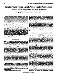
operate with both inductors in continuous current mode and only the dc-dc conversion was considered. The new topology is presented in figure 2. In the following , we present the operation regimes of this converter that can results in a very high input power factor and simultaneous output regulation. Referring to figure 2, the converter may be viewed as a cascade of a modified boost converter and a buck-boost converter. The switches are turned on and off synchronously.The modified boost converter operates in discontinuous current mode, while the buck-boost converter operates in continuous current mode. Since a high power factor is naturally achieved in this way, a simple feedback scheme suffices to regulate the output.
Fig. 1. Conventional SEPIC Converter The SEPIC converter was primarily designed to provide a non-pulsating input current. As shown in figure 1, the converter has two inductors that can shape the input current and feed the output load. In its original version, the SEPIC converter was designed to
ISSE 2001
'm
i'Q
i
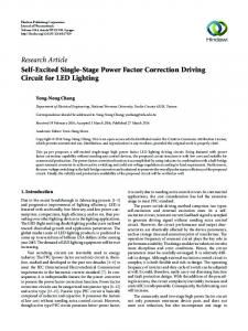
Fig. 2. The Proposed Converter In the following , we present the operation regimes
117
0-7803-7111-9/01/$10.0002001 IEEE
24th International Spring Seminar on Electronics Technology May 5-9, 2001, Calimanesti-Caciulata,Romania of this converter that can results in a very high input power factor and simultaneous output regulation. Referring to figure 2, the converter may be viewed as a cascade of a modified boost converter and a buckboost converter. The switches are turned on and off synchronously.The modified boost converter operates in discontinuous current mode, while the buck-boost converter operates in continuous current mode. Since a high power factor is naturally achieved in this way, a simple feedback scheme suffices to regulate the output. Compared with the conventional SEPIC topology operating in the same regime, the proposed converter demonstrates improved operation range. The some of the disadvantages of the conventional SEPIC converter are: 0 Higher switcWdiode peak -voltage stress compared with the proposed modified boost topology. Bellow are presented the values of the switches peak voltages stress for the conventional SEPIC topology and the proposed topology:
Fig 4. The Equivalent Circuits a) mode I b)mode I1 In the steady-state, during the interval when the switches are on (mode I), both inductance currents flow through -the switches and discharges the capacitor C (figure 4a). In the same time, the output capacitor COis discharging on the load resistor. In this operation mode, the following equations can be written:
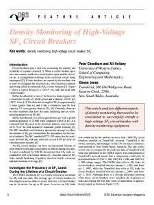
Impossibility to naturally obtain a unit power factor for higher output power. The waveforms for input voltage and input current for the conventional SEPIC converter are presented in figure 3.
.
ic =iL 1 +iL
(5)
When the switches are off (mode II), the current of LI inductor flows through diodes DI and DZ,and charges up the capacitor C, while the current of L2 inductors is forced into the free-wheeling diode D4 When the value of L1 current become zero, the charging of the capacitor stop. The current of Lz keeps free-wheeling through D4 diode. The cycle ends at the instant the switches are turn on again. The previous mentioned sequence repeats with period T,. In this operation mode, the following equations can be written:
r---------------------------------I
I
I
I I
I
I
- - - - --- - - - - - - - - - - - r - - - - - - - - - - - - - - -l --
Oms
lOms
(4)
2
2"
Fig. 3. Input Voltage and Input Current for the Conventional SEPIC Converter
2. PRINCIPLES OF OPERATION
. .
Referring to figure 2, the value of LI is relatively small so that the current through L, is maintained in discontinuous mode. The value of L2, on the other hand, is large enough to keep the output current in continuous mode. The operations modes of this converter are presented bellow:
(7)
The corresponding waveforms are presented in figure 5 .
3. CALCULATION OF INPUT POWER FACTOR AND THD FOR CONSTANT-FREQUENCY OPERATION The input power factor of the proposed converter under no specific control action can be calculated with the following formula: p.f.=
e n
E,, . I 4 rms ISSE 2001
118
0-7803-71 11-9/01/$10.00 02001 IEEE
24th International'SpringSeminar on Electronics Technology May 5-9, 2001, Calimanesti-Caciulata, Romania
(I+$)
V, D 2 ~ s
(1-6) LI
iu
(. Esinwt) ih (ut)=
V,D~T,
4
Hence, the power factor of the proposed converter, with no feedforward control is: E sin at
Fig. 5. Operating Waveforms
E sin wt
(9) 0
p.j-.=g
and e ( w t ) = E sin wt , w=2.n50 rads
A simple way to calculate these values is to calculate the average value of L, current in the steadystate operation. Over a one switching cycle, we can write the following relations:
Also, the total harmonic distortion (THD) can be found as:
The figure 6 shows a plot of the power factor versus ENc ratio.
ISSE 2001
119
0-7803-7111-9/01/$10.0002001 IEEE
24th International Spring Seminar on Electronics Technology May 5-9,200 1, Calimanesti-Caciulata, Romania
1...-....,
-.... .
-i
, --
--
0 81 o a1
08
' 0
01
I 01
' 03
'
I
I
I
I
I
04
OS
06
0'7
08
09
1
E vc
Fig. 6 Power Factor Plot
4. SIMULATION RESULTS For the purpose of illustration, we simulate the proposed converter operation, using real devices for the converter. The simulated results should adequately reflect the ability of the proposed topology achieving unity power factor. The circuit simulated has LI=20pH, L2=2mH, C=100pF, C,=220uF, RL=IOR and e=llOsin2n5t, with output to be regulated at 80V and the switching frequency is 20KHz. Figure 7 show the input voltage, the iL1current waveforms and the iL2 current spectrum.
converter used in power factor correction circuits. The modified SEPIC converter is designed to operate as a ac-dc converter and it can be viewed as a cascade of a modified boost converter and a buck-boost converter. The boost converter operates in discontinuous current mode, while the buck-boost converter operates in continuous current mode. Since a high power factor is naturally achieved in this way, a simple feedback control technique is needed in order to regulate the output voltage. In the paper is also presents a calculus method for the power factor and total harmonics distortion factor for the proposed converter. The proposed converter can be a useful circuit for power factor correction, using a modified SEPIC converter which naturally achieved a high power factor and a simple circuit for the output regulation. .
5. REFERENCES
.......................................................................................,
I
,m
i
111
"
M. Gotfryd, "Output Voltage and Power Limits in Boost Power Factor Corrector Operating in Discontinuous Inductor Current Mode", IEEE Transactions on Power Electronics, vol. 15, Jan., 2000 H.Braga, Ivo Barbi, "A Unity Power Factor Rectifier Based on a Two-Cell Boost Converter Using a New Parallel-Connection Technique", Proc. Of IEEE PESC, 1996 L.Huber, M.Jovanovic, "Single-Stage SingleSwitch Input-Current-Shaping Technique with Fast-Output-Voltage Regulation", IEEE Transactions on Power Electronics, vol. 13, May, 1998 R.\Y.Erickson, "Fundamental of Power Electronics", Kluwer Academic Publisher, 1999 Mohan, T.M.Undeland, W.P.Robbins, "Power Electronics:Converters, Applications and Design", 2"d Edition, John Willey&Sons,Inc, New York,
............................................................................................
0
S.Cuk: Switching dc-to-dc Converter with Zero Input or (Output Ripple ", Proceedings of the Industrial Applications Society Annual Meeting, Oct. 1978 C.K.Tse, M.H.L.Chow, '' Single Stage High Power Factor Converter Using the Sheppard-Taylor Topology, Proc. of IEEE PESC, 1996
Frlg"e"Cy
Fig. 7. a) Input Voltage, iL1Current Waveforms i~~Current Spectrum.
b)
5. CONCLUSIONS This paper presents a new topology of a SEPIC
ISSE 2001
120
0-7803-7111-9/01/$10.0002001 IEEE