1, 3 College of Electronic Information Engineering, Wuhan University of Science ... 2 Department of Aeronautical and Automotive Engineering, Loughborough ...
Power Flow Control of a Distributed Generation Unit in Micro-grid Yong Xue1, Jiamei Deng2, and Shuangbao Ma3 1, 3
College of Electronic Information Engineering, Wuhan University of Science and Engineering, 430073, P. R. China 2 Department of Aeronautical and Automotive Engineering, Loughborough University, UK
Abstract-Distributed generation units in micro-grid can be connected to utility grid as alternative energy sources besides providing power to their local loads. The distributed generation units are interfaced with utility grid using inverter. With inverter control, both active and reactive power pumped into the utility grid from the distributed generation units can be controlled. Reactive power �ow control allows the distributed generation units to be used as static var compensation units besides energy sources. This paper has presented a power �ow control approach for a DG unit in micro-grid. The proposed approach achieves decoupled P and Q control under grid-connected mode, an integral approach to conduct the power �ow control has been developed to control P by adjusting the power angle and control Q by adjusting the filter capacitor voltage. This paper has described control system algorithm for the proposed power controller. Simulation and experiment results have demonstrated strong P and Q regulation capability, fast enough response, and purely sinusoidal line current.
I.
INTRODUCTION
Power quality, safety and environmental concerns and commercial incentives are making alternative energy sources, e.g., photovoltaic devices, wind power, fuel cells, and gas-�red micro-turbines, more desirable. Micro-grid is comprised of several alternative energy sources. They are connected in addition to the main power grid and are placed on the site that is to use for the local load. That is it is connected to the low voltage distribution network through power electronics. Micro-grid is being applied and focused increasingly due to the fact that conventional electric power systems are being more and more stressed by expanding power demand, limit of power delivery capability, complications in building new transmission lines, and blackouts. A distributed generation (DG) unit in micro-grid is important element to maintain the balance between load and generated power, and to guarantee the quality of supply on an acceptable level. Developments in power electronics and digital control technology are providing more possibility and better �exibility of using these new sources in conventional electric power systems, to not only increase electric energy production but also help to enhance the power system stability via power �ow control. Previous research results have shown that DG could have signi�cant impacts on transmission system stability at heavy
����������������������������嘋�����,(((
penetration levels [1], where penetration is de�ned as the percentage of DG power in total load power in the system. A DG unit affects the system stability by generating or consuming active and reactive power. Therefore, power control performance of the DG unit determines its impact on the utility grid it connects to. If the power control performance is good, the DG unit can be used as means to enhance the system stability and improve power quality; otherwise it could undermine the system stability. Control issues of the DG unit in micro-grid have been addressed by a number of researches. Some past researches on line interactive inverters [2]–[6] only concentrate on current waveform control where power control is not considered. Although current waveform control is one of the goals of the inverter control, power control performance must be addressed before it can be practically connected to any power system. Liang et al. [7] have presented a power control method for a grid-connected voltage source inverter which achieves good P Q decoupling and fast power response. However, this approach requires knowledge of the value of power system equivalent impedance, which is impractical. Even though the possible error in the power factor angle of the impedance has been considered, it is the magnitude of the impedance that truly causes the sensitivity of P and Q responses, which is however not addressed. Therefore, the effectiveness of the control approach claimed in [7] is undermined. II.
THE POWER FLOW CONTROL SYSTEM
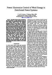
The proposed control solution is developed for a DG unit in micro-grid under grid-connected mode shown in Fig. 1. The DG unit consists of a DC bus powered by any DC source or AC source with a recti�er, a voltage source inverter, an LCL �lter stage, a isolation transformer with secondary side �ltering. The utility protection switch Su is governed by a local utility, while the inverter interactive switch Si is governed by the the DG unit. When the grid power is normal, the utility protection switch Su and the inverter interactive switch Si are all in ON state. The utility grid is modeled as an equivalent three-phase AC source with an equivalent internal impedance. Under grid-connected mode, the DG unit conducts power control, where the output active power P and reactive power Q from the DG unit to the utility grid should be regulated to desired values Pref and Qref . Both Pref and Qref can be positive
2122
,3(0&����
Lf
T1
D1
T3
Lg Io
Cf C Vdc T2
D2
T4
Su
D3
Vcf
DC
Si
Emergency Load
Vs
AC
Vs
D4
1:1
Fig. 1. Single-phase grid-connected DG unit
or negative, which provides possibility for the DG unit to help with the energy production and stability enhancement of the power system or sustain power supply to local load when it exceeds the capacity of the DG. The control goal of power regulation is stability, low static error, and fast response. Since the DG unit uses a voltage source inverter, its output active and reactive power are determined by the unit’s output voltage, including magnitude and phase angle, as stated in
P = Vs (Vcf sin δ / X )
(1)
Q = (Vcf2 − Vcf Vs cos δ ) / X
(2)
where Vs is the equivalent main voltage, X is the equivalent line reactance where the resistance is ignored, and � is the power angle - the phase angle difference between phase angle associated Vs and phase angle associated Vcf. Since the DG unit output voltage control already exists, the task of the power controller is to generate voltage command for the voltage controller based on the desired power values Pref and Qref and actual values P and Q. It is apparent that the desired DG output voltage V and the power angle � can be calculated from (1) and (2) given desired P and Q values and system parameter X. If this is true, the power control problem is solved. However, in practical systems, the above approach is not feasible. A large capacity power system is assumed in this research, where the value of X must be small. Practically, the value of X cannot be precisely known and may change due to the operation of the power system. Once an inaccurate value of X is used in the control, the error of X will lead to poor tracking and even instability. Therefore, power control solutions requiring knowledge of X cannot be practically used. It can be observed from (1) and (2) that both P and Q will be affected by only adjusting one of V and ¥, which is so called coupling between P and Q. However, variations of V and � have different levels of impact on P and Q as described in the following partial derivatives
∂P / ∂δ = Vs (Vcf cos δ / X )
(3)
∂P / ∂Vcf = Vs (sin δ / X )
(4)
∂Q / ∂δ = (Vcf Vs sin δ ) / X
(5)
∂Q / ∂Vcf = (2Vcf − Vs cos δ ) / X
(6)
When δ is small which is true for large capacity power systems, ∂P / ∂δ is close to Vs (Vcf / X ) and ∂P / ∂Vcf is close to 0 and reversely, ∂Q / ∂δ is close to 0 and ∂Q / ∂Vcf is close to (2Vcf − Vs ) / X . This fact indicates that P is more sensitive to � and Q is more sensitive to Vcf especially when the DG unit is connected to a large capacity system where the power angle � is usually small. The different levels of sensitivity of P and Q to � and Vcf provide a chance to control P and Q relatively independently, not completely independently though. Based on the above analysis, an integral approach to conduct the power �ow control can be developed to control P by adjusting � and control Q by adjusting Vcf. If the phase angle associated to the system voltage Vs is assumed to be 0, � is the phase angle associated to Vcf. The voltage and phase angle references can be generated as
δ ref = δ 0 + ³ K p ( Pref − P)dt
Vref = V0 + ³ K q (Qref − Q)dt
(7) (8)
where δ 0 and V0 are the initial voltage and phase angle at the moment that the DG unit is connected to the grid from island running mode. The proposed power controller is illustrated in Fig. 2. The P and Q control loop regulate active power and reactive power slowly in the frequency domain, while the voltage control loop controls the filter capacitor voltage in the time domain. In Fig. 2 δ s is the phase angle associated to the system voltage Vs, it is generated by a PLL (phase-locked loop) circuit. The resultant phase angle summation ( δ ref + δ s ) is sent to the augment for a sine function. In the proposed power regulation approach, P and Q controls are decoupled under steady state due to the integration of the errors. However, in the transient, the P and Q coupling cannot be eliminated. Both P and Q are nonlinear function of Vcf and �. Due to the coupling and nonlinearity, the stability of the power control must be investigated.
2123
Fig. 2. Control system block diagram for the proposed power controller .
δ = K p ( Pref − VsVcf δ / X ) .
4000
V cf = K q (Qref − Vcf (Vcf − Vs ) / X )
P(t) Q(t)
3000
1000 P&Q(W/Var)
(10)
The stability of the power loop can be evaluated using Lyapunov’s direct method where there is no external excitation, i.e., Pref= 0 and Qref= 0. A Lyapunov function can be defined as 1 1 ξ (Vcf , δ ) = (Vcf − Vs ) 2 + δ 2 (11) 2 2 The derivative of the above function is
2000
0
-1000
-2000
.
.
.
ξ (Vcf , δ ) = Vcf䯴 Vcf − Vs ) + δ δ
-3000
-4000 1
(9)
2
3
4
5 Time(s)
6
7
8
= − K qVcf䯴 Vcf − Vs ) 2 / X − K p δ 2Vcf Vs / X
9
(12)
•
From (12), it can be observed that ξ (Vcf , δ ) < 0 holds when (Vcf-Vs) ≠ 0 and � ≠ 0 , given positive values of K p , K q , Vcf , Vs and X. therefore the proposed power control loop is stable.
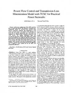
Fig. 3. Simulation waveforms for P, Q regulation
3500
III. 3000
P(W)
2500
2000
1500
1000
500 2
3
4
5 Time(s)
6
7
8
Fig. 4. Experimental waveforms for P regulation
Assuming large capacity power system with small power angle �, it is reasonable to have sin δ ≈ δ and cos δ ≈ 1 , Equation (7) and (8) can be rewritten in differential format
SIMULATION AND EXPERIMENT RESULTS
Simulations have been run on a 5kVA DG unit with a topology shown in Fig. 1 connected to a 220V line-to-neutral power system with an equivalent reactance 1�. Under grid-connected mode, P and Q output to the utility grid need to be controlled for system stabilizing, compensation, or handling local load disturbances. Fig. 3 illustrates the P and Q regulation under various step references. It can be observed from Fig. 3 that the settling time is about 0.5 sec. for P response and 0.2 sec. Even though some minor coupling between P and Q is seen in the transients, the steady state decoupling is achieved with the control. To verify proposed power �ow control of a DG unit, an experimental inverter system has been established as shown in Fig. 1. The control algorithm for the experimental system is implemented fully digitally as shown in Fig. 2. The rated input line-line voltage from the solar-cell array is 280V. The output of the inverter is connected to the grid and emergency load. The normal grid voltage is 220V and grid frequency is 50Hz. The
2124
switching frequency is 20KHz. The rated output power is 5KW. Fig. 4 shows the experimental waveforms for P regulation. IV.
CONCLUSION
This paper has presented a power �ow control approach for a DG unit in micro-grid. The proposed approach achieves decoupled P and Q control under grid-connected mode. Simulation and experiment results have demonstrated strong P and Q regulation capability, fast enough response, and purely sinusoidal line current. The stability of the power control loop is proved using Lyapunov direct method. REFERENCES [1] M.K. Donnelly, J.E. Dagle, D.J. Trudnowski, and G.J. Rogers, “Impacts of the distributed utility on transmission system stability,” IEEE Transactions on Power Systems, vol. 11, Ĉ. 2, pp. 741-746, May 1996. [2] N. Abdel-Rahim and J.E. Quaicoe, “A single-phase voltage-source utility interface system for weak AC network applications,” in Proc. 1994 IEEE Applied Power Electronics Conference and Exposition, Orlando, FL, USA, vol. 1, pp. 93-99, Feb. 1994. [3] Yong Xue, Yuchuan Wu. “An Adaptive Predictive Current-Controlled PWM Strategy for Single-Phase Grid-Connected Inverters,” Industrial Electronics Society, 2007. IECON 2007. 33rd Annual Conference of the IEEE. Page(s):1548 – 1552, 5-8 Nov. 2007. [4] J. Rajagopalan and B.H. Cho, “Space-vector modulated PWM converters for photo-voltaic interface applications: analysis, power management and control issues,” in Proc. 1995 Applied Power Electronics Conference and Exposition, Dallas, TX, USA, vol. 2, pp. 814-820, March 1995,. [5] T. Takeshita, T. Masuda, and N. Matsui, “Current waveform control of distributed generation system for harmonic voltage suppression,” in Prod. 2001 IEEE 32nd Annual Power Electronics Specialists Conference, Vancouver, BC, Canada, vol. 2, pp. 516-521, June 2001. [6] Hyosung Kim, Taesik Yu, and Sewan Choi, “Indirect current control Algorithm for Utility Interactive Inverters in Distributed Generation Systems,” IEEE Transactions on Power Electronics, Vol. 23, Ĉ. 3, pp. 1342-1347, May 2008. [7] J. Liang, T.C. Green, G. Weiss, and Q.C. Zhong, “Evaluation of repetitive control for power quality improvement of distributed generation,” in Proc. 2002 IEEE Power Electronics Specialists Conference, Cairns, Qld., Australia, vol. 4, pp. 1803-1808, June 2002.
2125