A. Ghosh, S. Hloch
Predviđanje i optimizacija parametara popuštanja za proces potopnog elektrolučnog zavarivanja ISSN 1330-3651 (Print), ISSN 1848-6339 (Online) UDC/UDK 621.791.75:[519.863:519.23.5]
PREDICTION AND OPTIMIZATION OF YIELD PARAMETERS FOR SUBMERGED ARC WELDING PROCESS Aniruddha Ghosh, Sergej Hloch Original scientific paper This study is conducted to predict the weld bead geometry, mechanical properties and HAZ dimensions by developing mathematical models following statistical methods. The developed mathematical models in which the data is represented can be programmed, fed to a computer and used to develop an expert welding system. MATLAB and MS Excel are used for the complete analysis. Finally optimum setting of output responses was investigated through graphical method. Keywords: mathematical model, regression analysis, submerged arc welding, weld bead quality
Predviđanje i optimizacija parametara popuštanja za proces potopnog elektrolučnog zavarivanja Izvorni znanstveni članak Ova studija je provedena kako bi se predvidjela geometrija zavarenog sloja, mehanička svojstva i dimenzija zone oko zavara u kojoj toplina uzrokuje trajne promjene, razvojem matematičkih modela slijedeći statističke metode. Razvijeni matematički modeli u kojima su predstavljeni podaci mogu biti programirani, učitani u računalo i rabljeni za razvoj ekspertnih sustava za zavarivanje. MATLAB i MS Excel rabljeni su za potpunu analizu. Na kraju su istražene optimalne postavke izlaznih odgovora pomoću grafičke metode. Ključne riječi: kvaliteta zavarenog sloja, matematički model, potopno zavarivanje, regresijska analiza
1
Introduction
Submerged Arc Welding is one of the major welding processes in industry because of its inherent advantages, including deep penetration and a smooth bead. Lots of critical sets of input parameters are involved in Submerged Arc Welding Process which needs to be controlled to get the required weld bead quality [1 ÷ 4]. Detailed information on effects of input parameters on weld bead quality parameters and finding out the relationship between them are very essential for decreasing trial run of SAW process. Reducing of trial run is essential to reduce the cost of welding procedure also [5, 6]. For the submerged arc welding plates, engineers often face the problem of selecting appropriate combination of input process control variables for achieving the required weld bead quality or predicting the weld bead quality for the proposed process control values [7]. For automatic SAW, the control parameters must be fed to the system according to some mathematical formula to achieve the desired results [8 ÷ 13]. These important problems can be solved with development of mathematical models through effective and strategic planning, design of execution of experiments. These models facilitate optimization of the process. Development of mathematical models also helps to improve the understanding of the effect of process parameters on bead quality and HAZ width to obtain a high-quality, to evaluate the interaction effects of bead parameters and to optimize the bead quality and HAZ width, to obtain a high-quality welded joint at a relatively low cost with high productivity. In the present work, prediction of the weld bead geometry and HAZ dimensions by developing mathematical models following statistical methods was done and optimum setting of output responses was investigated through graphical method to get better bead quality and minimum HAZ width.
Tehnički vjesnik 20, 2(2013), 213-216
2
Experimental method
The experiments were conducted as per the design matrix randomly to avoid errors due to noise factors. The mild steel work piece (150 × 150 × 12 mm – 2 pieces) is cut and V groove of angle 60° as per the standards is prepared. The chemical composition of work piece material is described in Table 1. The job was firmly fixed to a base plate by means of tack welding and then the submerged arc welding was finally carried out. The welding parameters were recorded during actual welding to determine their fluctuations, if any. The slag was removed and the job was allowed to cool down. Welding is carried out for the square butt joint configuration. The job is cut at three sections for similar welding conditions. No. 1 2 3
Table 1 Welding process variable and their limits Parameters Unit Notation Levels Current A I 200, 400, 600 Voltage V U 24, 42, 60 Travel speed cm/min v 39, 57, 75
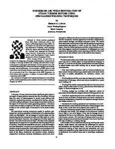
Figure1 Weld bead geometry: penetration (P), reinforcement height (H), Width (W) and HAZ.
213
Prediction and optimization of yield parameters for submerged arc welding process
Dependent Constant Independent No variable input variable (mm) parameter(s)
1
P
I
U, v
2
P
U
I, v
3
P
v
I, U
4
W
I
U, v
5
W
U
I, v
6
W
v
I, U
7
H
I
U, v
8
H
U
I, v
9
H
v
I, U
10
P
U, v
I
A. Ghosh, S. Hloch
Table 2 Details of mathematical model Values of constant input Mathematical model parameter(s)
U = 25 V v = 39 cm/min I = 400 A v =39 cm/min I = 400 A U = 25 V U = 25 V S = 39 cm/min I = 400 A v = 39 cm/min I = 400 A U = 25 V U = 25 V v = 39 cm/min I = 400 A v = 39 cm/min I = 400 A U = 25 V I = 400 A
R2 (%)
P = 3,6 − 0 ,002 ⋅ I + 4 ,2 × 10 −6 ⋅ I 2
96,6
P = CONSTANT
-
P = 3 − 0,002 ⋅ v − 0,00074 × 10 −6 ⋅ v 2
97
W = 17 − 0 ,017 ⋅ I + 2 ,3 × 10 −6
96
W = −50 + 4 ,4 ⋅ U − 0 ,065 ⋅ U 2
98
W = 12 + 0 ,37 ⋅ v − 0 ,0084 ⋅ v 2
95,5
H = 1,1 + 0 ,022 ⋅ I − 2 ,1× 10 −6 ⋅ I 2
96
H = CONSTANT
-
H = 2 ,2 + 0 ,035 ⋅ v + 0 ,00045 ⋅ v 2
98
P = 2 ,14 − 0 ,13 ⋅ v + 0 ,0078 ⋅ v 2 + 0 ,026 ⋅ U 2 + 0 ,005 ⋅ U
88
2
2
11
P
I, v
U
U = 25 V
P = −0,95 ⋅ v + 0 ,018 ⋅ v − 2 ,21 ⋅ I + 0,14 ⋅ I − 0 ,8 ⋅ I ⋅ v
99
12
P
I, U
v
v = 39 cm/min
P = −0 ,1542 ⋅ U + 0 ,0518 ⋅ I + 0 ,0052 ⋅ U 2 − 0 ,001 ⋅ U ⋅ I
99
13
B
U, v
I
I = 400 A
W = 10 ,4 − 0 ,6 ⋅ v + 0 ,04 ⋅ v 2 + 0 ,17 ⋅ U + 0 ,076 ⋅ v ⋅ U
94
2
14
B
I, v
U
U = 25 V
W = 11 − 0 ,02 ⋅ v + 0 ,46 ⋅ v + 0 ,4 ⋅ I
96
15
B
I, U
v
v = 39 cm/min
W = 0 ,7001 ⋅ U + 0 ,0256 ⋅ I − 0 ,0076 ⋅ U 2 − 0 ,0008 ⋅ U ⋅ I
99
2
2
16
L
U, v
I
I = 400 A
H = 1 + 0 ,01 ⋅ v + 0 ,02 ⋅ U + 0 ,04 ⋅ U + 0 ,05 ⋅ U ⋅ v
96
17
L
I, v
U
U = 25 V
H = −0 ,6 ⋅ v + 0 ,02 ⋅ v 2 − 2 ,2 ⋅ I + 0 ,06 ⋅ I 2 − 0 ,42 ⋅ v ⋅ I
95
18
L
I, U
v
v = 39 cm/min
2
H = −0 ,072 ⋅ U + 0 ,0175 ⋅ I + 0 ,0023 ⋅ U − 0 ,0004 ⋅ U ⋅ I
98
P = 201,22 − 38,9 ⋅ v + 211,09 ⋅ U − 16 ,4 ⋅ I + 0 ,94 ⋅ v 2 − 8,35 ⋅ U 2 + 19
P
I, U, v
-
-
+ 0 ,05 ⋅ I 2 + 0 ,43 ⋅ v ⋅ U + 0 ,07 ⋅ v ⋅ I − 0 ,03 ⋅ U ⋅ I − 0 ,02 ⋅ v 3 + 3
3
+ 0 ,11 ⋅ U ⋅ U + 0 ,07 ⋅ v ⋅ I − 0 ,03 ⋅ U ⋅ I − 0 ,02 ⋅ v + 0 ,11 ⋅ U 20
H
I, U, v
-
-
21
MDR
I, U, v
-
-
22
HW
I, v
U
U = 25 V
H = −139 ,85 − 7 ,52 ⋅ v − 16 ,79 ⋅ U + 2 ,81 ⋅ I − 0 ,03 ⋅ v 2 + + 0 ,35 ⋅ U 2 − 0 ,01 ⋅ I 2 + 0 ,4 ⋅ v ⋅ U + 0 ,03 ⋅ v ⋅ I + 0 ,03 ⋅ U ⋅ I
MDR = 83,63 − 1,79 ⋅ v − 2 ,54 ⋅ U − 16 ,4 − 0 ,4 ⋅ I + + 0 ,02 ⋅ v 2 + 0 ,06 ⋅ U 2 + 0 ,05 ⋅ v ⋅ U
HW = 2 + 0 ,35 ⋅ I + 0 ,05 ⋅ I 2 + 0 ,08 ⋅ I ⋅ v
23
HW
I, U
v
v = 39 cm/min
HW = 0 ,0803 ⋅ U − 0 ,0012 ⋅ I − 0 ,0011 ⋅ U
24
HW
v, U
I
I = 400 A
HW = 2 − 0 ,07 ⋅ v + 0 ,3 ⋅ U + 0 ,04 ⋅ U 2
25
HH
I, v, U
-
-
26
BH
v, U
I
I = 400 A
The samples are prepared by a standard metallographic process and the average values of the penetration, reinforcement height, and width are measured using digital venire caliper of least count 0,02 mm. Fig. 1 depicts the weld dimensions of SAW considered in present work. The measured values of weld dimensions 214
99
3
98,8 97 97
2
HH = 4 ,1 + 0 ,007 ⋅ U 2 + 0 ,000025 ⋅ I 2 − 0 ,0009 ⋅ I ⋅ U + + 0 ,00018 ⋅ v 2 + 0 ,0002 ⋅ I ⋅ v
BH = −23,6 ⋅ v − 0 ,08 ⋅ v 2 − 29 ⋅ U − 0 ,5 ⋅ U 2 − 7 ,3 ⋅ v ⋅ U
98 78 89 89
and corresponding welding conditions are described in Table 2. With the help of optical research microscope HAZ width(s) are measured. Mathematical models (Table 2) have been developed by following multi regression method.
Technical Gazette 20, 2(2013), 213-216
A. Ghosh, S. Hloch
3
Predviđanje i optimizacija parametara popuštanja za proces potopnog elektrolučnog zavarivanja
Results and discussions
Optimization of yield parameters of SAW process: Every machine has some limitations. It cannot run any value of input variable. Every machine is able to run with the same range of values input variables. Suppose a submerged arc welding machine is able to work between 25 V to 35 V but optimum value of one of input variables (voltage) is 1 V. It is not acceptable because this machine cannot work in 1 V. So, in present work, graphs of output responses (comp. Figs. 2÷9) of SAW process were drawn with the help of mathematical model (described in Tab. 2), considering input variables with their range (described in Tab. 1) and from these graphs (Figs. 2÷9) optimum setting of input variables and values of output responses were presented in Tab. 3. From Figs. 2 and 3, it has been found that when the value of current is high then the penetration is high and when the current is low then the value of penetration is low and there is nominal effect of voltage on penetration. Sl. No. 1 2 3 4
Table 2 Results of optimum solution of SAW process Travel speed Output Figure (const. assumed) response No. cm/min Penetration = 599 47 39 2&3 7,22 mm Reinforcement 600 50 39 height = 0,68 4&5 mm Bead width = 597 50 39 6&7 0,68 mm HAZ width = 600 50 39 8&9 0,55 mm
Figure 3 Contour plot for output variable penetration
Current Voltage (A) (V)
Figure 2 3D plot when input variables are voltage and current and output variable is Penetration
Figure 4 3D plot when input variables are voltage and current and output variable is Reinforcement height
Figure 5 Contour plot for output variable Reinforcement height
From Figs. 4 and 5, it has been found that reinforcement height increases with the increase of current but reinforcement height is not so affected by voltage. From Figs. 6 and 7, it has been found that current has negative effect on bead width but voltage has a positive effect on bead width. From Figs. 8 and 9, it has been found that, up to a certain value of voltage, HAZ width increases after that voltage has a negative effect on HAZ width and HAZ width is more affected by voltage with respect to current.
Figure 6 3D plot when input variables are voltage and current and output variable is bead width Tehnički vjesnik 20, 2(2013), 213-216
215
Prediction and optimization of yield parameters for submerged arc welding process
Figure 7 Contour plot for output variable bead width
Figure 8 3D plot when input variables are voltage and current and output variable is HAZ width
Figure 9 Contour plots for output variable HAZ width
4
Conclusion
A. Ghosh, S. Hloch
mechanics parameters. // Tehnicki vjesnik-Technical Gazette, 17, 3(2011), pp. 333-340. [3] Younise, B.; Rakin, M.; Medjo, B.; et al. Numerical analysis of constraint effect on ductile tearing in strength mismatched welded CCT specimens using micromechanical approach. // Tehnicki vjesnik-Technical Gazette, 17, 4(2010), pp. 411418. [4] Sharma, A.; Chaudhary, A. K.; Arora, N.; et al. Estimation of heat source model parameters for twin-wire submerged arc welding. // International Journal of Advanced Manufacturing Technology, 45, 11-12(2009), pp. 1096-1103. [5] Pillia, K. R.; Ghosh, A.; Chattopadhyaya, S.; Sarkar, P. K.; Mukherjee, K. Some investigations on the Interactions of the Process Parameters of Submerged Arc Welding. // Manufacturing Technology & Research (an International Journal), 3, 1(2007), pp. 57-67. [6] Ghosh, A.; Chattopadhyaya, S.; Sarkar, P. K. Output Response Prediction of SAW Process. // Manufacturing Technology & Research (an International Journal), 4, 3(2008), pp. 97-104. [7] Ghosh, A.; Chattopadhyaya, S. Prediction of Weld Bead Penetration, Transient Temperature Distribution & HAZ width of Submerged Arc Welded Structural Steel Plates. // Defect and Diffusion Forum, 316-317(2011), pp. 135-152. [8] Gunaraj, V.; Murugan, N. Prediction and Optimization of Weld Bead Volume for the Submerged Arc Welding Process-Part-1 // Welding Research (2000), pp. 286s-294s. [9] Gunaraj, V.; Murugan, N. Prediction and Optimization of Weld Bead Volume for the Submerged Arc Welding Process-Part-2. // Welding Research, November (2000), pp. 331s-337s. [10] Gunaraj, V.; Murugan, N. Prediction of Heat Affected Zone Characteristics in Submerged Arc Welding in Structural Steel Pipes. // Welding Research, January, (2002), pp. 94s-98s. [11] Ghosh, A.; Singh, N. K.; Chattopadhyaya, S. 3rd Degree Mathematical Model Appropriate for Parametric Estimation of SAW process. //Advanced Materials Research, 284- 286, (2011), pp. 2473-2476. [12] Ghosh, A.; Chattopadhyaya, S.; Hloch, S. Prediction of weld bead parameters, transient temperature distribution & HAZ width of submerged arc welded structural steel plates. // Tehnicki vjesnik-Technical Gazette, 19, 3(2012), pp. 617620. [13] Michalec, I.; Maronek, M.; Barta, J.; et al. Weld joints fatigue properties of thin carbon steel sheet treated by nitrooxidation. // Tehnicki vjesnik-Technical Gazette, 19, 1(2012), pp. 65-69.
Nomenclature
Condition for optimization of submerged arc welding process is maximum penetration, minimum reinforcement height, bead width and HAZ width. It has been found from graphs (Figs. 2 ÷ 9) for this case maximum penetration is 7,22 mm, minimum reinforcement height is 0,68 mm, minimum bead width is 0,68 mm and minimum HAZ width is 0,55 mm. So optimum input parametric setting is 50 V (voltage), 600 A (current), 39 cm/min (travel speed).
P – penetration (mm), H – reinforcement height (mm), W – bead width (mm), HW – HAZ width (mm), I – current (A), U – voltage (V), v – travel speed (cm/min), MDR – metal decomposition rate (kg/min), HH – HAZ hardness (HB), BH – bead hardness (HB) and R2 – regression coefficient (–).
5
Aniruddha Ghosh Dept. of Mechanical Engineering, Govt. College of Engg. & Textile Technology, Berhampore, WB, India E-mail:
[email protected]
References
[1] Matesa, B.; Kozak, D.; Stoic, A.; et al. The influence of heat treatment by annealing on clad plates residual stresses // Metalurgija, 50, 4(2011), pp. 227-230. [2] Vukojevic, N.; Oruc, M.; Vukojevic, D. et al. Performance analysis of substitution of applied materials using fracture
216
Authors' addresses
Sergej Hloch Faculty of Manufacturing Technologies of Technical Universtity of Košice with a seat in Prešov Bayerova 1 080 01 Prešov, Slovak Republic Technical Gazette 20, 2(2013), 213-216