M. Sonntag
K. Görlach
D. Karastoyanova
F. Leymann
M. Reiter
Process Space-Based Scientific Workflow Enactment Stuttgart, July 2010 Institute of Architecture of Application Systems (IAAS) University of Stuttgart, Universitaetsstrasse 38 70569 Stuttgart, Germany {Sonntag, goerlach, karastoyanova, leymann, reiter}@iaas.uni-stuttgart.de www.iaas.uni-stuttgart.de Abstract In the scientific field, workflow technology is often employed to conduct computer simulations or computer supported experiments. The underlying IT infrastructure typically comprises resources distributed among different institutes and organisations all over the world. Traditionally, workflows are executed on a single machine while the invoked software is accessed remotely. This approach imposes many drawbacks which are outlined in this paper. To address these weaknesses, we investigate the application of decentralised workflow enactment in the scientific domain. In this context, we explore the employment of process spaces, a middleware for the decentralised execution of workflows. Furthermore, we propose the combination of process spaces with the concept of data references to increase the overall performance of distributed simulations based on workflows. The considerations are discussed with the help of a scenario that calculates and visualises the ink diffusion in water over a period of time. Keywords business process execution language; BPEL; process space; scientific workflow; data references; distributed system. Reference Sonntag, M., Görlach, K., Karastoyanova, D., Leymann, F. and Reiter, M. (2010) ‘Process space-based scientific workflow enactment’, Int. J. Business Process Integration and Management, Vol. 5, No. 1, pp.32–44. © Inderscience Publishers http://www.inderscience.com/browse/index.php?journalID=115&year=2010&vol=5&issue=1
Stuttgart Research Centre for Simulation Technology (SRC SimTech) SimTech – Cluster of Excellence Pfaffenwaldring 7a 70569 Stuttgart
[email protected] www.simtech.uni-stuttgart.de
International Journal of Business Process Integration and Management, Volume X, No. X, 2010
1
Process Space-based Scientific Workflow Enactment Mirko Sonntag, Katharina Görlach, Dimka Karastoyanova, Frank Leymann, Michael Reiter Institute of Architecture of Application Systems University of Stuttgart Universitaetsstrasse 38 70569 Stuttgart, Germany E-mail: {sonntag, goerlach, leymann, karastoyanova, reiter} @iaas.uni-stuttgart.de Abstract: In the scientific field, the workflow technology is often employed to conduct computer simulations or computer supported experiments. The underlying IT infrastructure typically comprises resources distributed among different institutes and organizations all over the world. Traditionally, workflows are executed on a single machine while the invoked software is accessed remotely. This approach imposes many drawbacks which are outlined in this paper. To address these weaknesses we investigate the application of decentralized workflow enactment in the scientific domain. In this context, we explore the employment of process spaces, a middleware for the decentralized execution of workflows. Furthermore, we propose the combination of process spaces with the concept of data references to increase the overall performance of distributed simulations based on workflows. The considerations are discussed with the help of a scenario that calculates and visualizes the ink diffusion in water over a period of time. Keywords: BPEL, Process Space, Scientific Workflow, Data References, Distributed System. Biographical notes: Mirko Sonntag, Katharina Görlach, and Michael Reiter are PhD students in the DFG Cluster of Excellence Simulation Technology (EXC310) at the University of Stuttgart, Germany. Mirko Sonntag and Katharina Görlach hold a Master’s degree in Computer Science, Michael Reiter is a Master of Mathematics. Dimka Karastoyanova is a junior professor in simulation workflows at the IAAS and a member of the cluster of Excellence Simulation Technology (SimTech) at the University of Stuttgart, Germany. She has a PhD in Computer Science from the Technical University of Darmstadt, Germany. Frank Leymann is a full professor in Computer Science and director of the Institute of Architecture of Application Systems (IAAS) at the University of Stuttgart. His research interests are in the areas of application architectures, middleware, workflow management, service-oriented computing and cloud computing.
1 INTRODUCTION
Applications in the scientific domain need to meet different requirements: Huge amounts of data are processed. Since scientific applications are often complex there are performance requirements for the hardware used for running the application. Additionally, the IT infrastructure should be robust, scalable and extensible. As scientists need a proof of how certain results of other scientists have been achieved, the run of an application must be reproducible. Finally, scientists want to share their applications, data and hardware for the purpose of reuse and resource utilization.
In distributed systems people, information, software and hardware are dispersed [1]. The owners of computing nodes connect their systems in order to exchange and share information and resources. Additionally, distributed systems afford speed-up through parallel computing, especially for computing-intensive tasks such as those in scientific applications. Furthermore, distributed systems allow an incremental growth of the IT infrastructure. This means the integration of additional storage facilities or compute servers for more compute power is facilitated. Distributed applications ensure scalability by avoiding centralized components. Another advantage of decentralized components is that the availability of the system can be
2
MIRKO SONNTAG, KATHARINA GÖRLACH, DIMKA KARASTOYANOVA, FRANK LEYMANN, MICHAEL REITER
ensured even if a single component fails. The availability of services and information is achieved by redundant functionalities support and data replication. A downside of distributed systems is the increased effort for configuration and coordination. Previously unconnected components must be wired. The parts of distributed applications need to manage their interactions and handling of data while being located on different machines. Additional aspects of fault tolerance have to be considered, such as the unavailability of servers or networks. Distributed systems must be able to deal with these problems. Nevertheless, distributed systems fulfill a lot of requirements for scientific applications which qualifies them for practical use. The Web service (WS) technology [2] can be used for the integration of heterogeneous applications in a loosely coupled fashion. WSs are self-contained, self-describing pieces of functionality exposing stable interfaces. The WS descriptions are programming language and technology independent; the underlying implementation details of WSs are thereby hidden. To support meaningful application scenarios composability of services is a must and is a property enabled by the WS technology. Service orchestrations are compositions of WSs into processes (or workflows) that provide higher levels of functionality. The Business Process Execution Language (BPEL) [3] is the defacto standard to define machine-readable orchestrations of WSs. Since these workflows can again be exposed as WSs that may be incorporated into another workflow, BPEL enables a recursive aggregation model. BPEL fulfills basic requirements for scientific workflows, for example the support of exception handling, user interactions to facilitate interactive steering and monitoring, compensation mechanism, and the dynamic selection of services [4]. BPEL processes are executed by a so-called BPEL engine. The used WSs can be distributed among several partners throughout a network. Thus, BPEL can be used to implement distributed applications. Traditionally, a BPEL engine is part of a centralized workflow management system (WfMS). That means the workflow logic runs on a single server. This results in several drawbacks, such as the WfMS as single point of failure. In contrast to that, decentralized WfMSs distribute workflow logic across several participants what promises to gain multiple advantages. In this work, we investigate to what extent decentralized execution of workflows is advantageous in the scientific domain in general. Therefore we present a general discussion about centralized vs. decentralized WfMSs and subsequently we explain why the process space approach (also presented in the paper) fits best to serve as a basis for further development in the scientific workflows area. Process spaces are a middleware to execute workflows in a decentralized manner. We propose the use of this approach in the area of scientific workflows and present a scenario that is realized using this approach. Particular challenges arise especially when applying the solution in a highly dynamic environment. In this context, the challenges
we identify are related to the deployment and undeployment of scientific workflow models on distributed resources. Since scientific workflows typically deal with huge data sets, the process spaces will probably run into problems when handling data sets with a size of several mega bytes, for example. To address this weakness we propose the adoption of the BPEL data reference concept [5] for avoiding bulks of data in process spaces. Finally, we discuss the feasibility of the approach: We use a concrete scientific simulation workflow and demonstrate how it can be implemented by a centralized and a process space-based WfMS with and without data references. We compare and assess the different implementations and discuss application areas for the respective solutions. The remainder of the paper is structured as follows: Section 2 covers background information important for the rest of the paper. Section 3 presents related work in the areas of scientific workflows and distributed workflow enactment. Section 4 introduces a concrete scenario that is used for argumentation. Section 5 points out the general advantages when employing the process space-based workflow execution for scientific workflows. The set-up of the scenario is illustrated and the challenge of deploying distributed workflow models is touched. Additionally, the concept of data references in this context is examined. Section 6 compares the centralized and decentralized workflow execution and discusses the results. Section 7 provides a conclusion and gives future directions.
2 BACKGROUND
In this section we introduce the necessary background information for the rest of the paper. We explain centralized and distributed WfMSs and give a comparison between these two based on the application area of scientific workflows. Furthermore, we introduce the approach of a process space-based workflow enactment as an example for a distributed WfMS. 2.1 Centralized WfMSs
Workflow instances are carried out according to the control flow, data flow, and rules as prescribed by their models. A so-called navigator component follows the control and data flow of a workflow instance’s, supervises the accomplishment of the tasks to be done (e.g. the invocation of WSs), and keeps the status and the progress of the execution. Typically, executing workflows is done by the enactment service of a centralized WfMS. The term “centralized” denotes the WfMS as a single unit. However, such a centralized WfMS may be running across several nodes of a cluster. Nevertheless, even clustered navigators need to share state and thus rely on each other. Furthermore, a cluster is assumed to operate within a single domain or organization, such as a scientific institute.
PROCESS SPACE-BASED SCIENTIFIC WORKFLOW ENACTMENT
3
2.2 Distributed WfMSs
2.4 Process Space-based Workflow Enactment
As opposed to a centralized workflow execution the decentralized approach arbitrarily distributes the workflow (i.e. its coordination logic) among different independent machines of possibly different organizations. No single navigation component is needed anymore that supervises the overall workflow execution. There are different mechanisms that can be used to support the realization of decentralized WfMSs (e.g. message-oriented middleware, tuplespace middleware [6]).
The process space-based workflow enactment is an approach for the distributed execution of coordination logic [7]. Process spaces are shared, remotely accessible storages for tuples (ordered lists of typed fields, also referred to as tokens). Tuples can be retrieved and stored via three operations: out stores a tuple, in reads a tuple destructively, rd reads a tuple non-destructively. Reading tuples is done with the help of templates. A template prescribes criteria a demanded tuple must match to be fetched from the process space. Process space-based workflow enactment is conducted without a centralized navigator as known from traditional (i.e. centralized) workflow engines. Instead of that, the coordination is split among several so-called activity clients that are reading from and writing to process spaces. An activity client performs the coordination of a single activity. In case of a non-interacting activity, an activity client also implements the activity’s functionality. Activity clients have a very local view on the process. They only know the process spaces they access and thus are completely decoupled from each other. Workflow execution is performed with the help of two types of tuples, namely control tokens and data tokens, passed by activity clients. The coordination logic of the workflow model is represented by the token templates of the activity clients. A control bus can used to configure and manage activity clients at runtime (e.g. change their token templates). Process spaces also provide operations tailored for their application with workflows (e.g. the join of control flow branches). BPEL is used as underlying workflow meta-model. BPEL process models are split among process participants according to specific strategies and constraints [8] (called process segmentation), e.g. an activity must be carried out on a particular server. After segmentation, the BPEL process model is transformed into an Executable Workflow Network (EWFN). EWFNs are a special Petri net dialect. They realize the token passing mechanism and enable the execution of workflows on process spaces [9]. Finally, the EWFN model can be installed and executed on participating servers in form of process spaces and activity clients [10].
2.3 Centralized vs. Distributed execution of scientific workflows
In the scientific domain a typical setting consists of several special-purpose, distributed machines with different characteristics, for example servers with huge hard drives but relatively slow processors, or computers with efficient GPUs ideal for taking over visualization tasks. Being able to deploy and execute parts of a workflow on machines that provide the application logic significantly reduces the number of remote interactions. On the one hand, network traffic is decreased dramatically. On the other hand, calling applications locally is fast since the overhead of marshalling, transmitting, and demarshalling messages is reduced. In case of BPEL, WSs could be bound locally, for instance a Java class could be called natively. These arguments have even greater importance having in mind that scientific workflows typically process huge data sets. In contrast to a centralized system, a decentralized WfMS can process distributed workflows potentially fully parallel (as far as allowed by logical dependencies between activities (and cf. Amdahl’s law), and as long as there is no better clustered navigator solution). There is neither a sequentially working navigator nor need non-interacting activities (e.g. activities in BPEL) be carried out on the same server. Moreover, this approach precludes the navigator to become a potential bottleneck. The workload is thus distributed among all participants. The distributed enactment of a workflow over several machines increases the overall robustness of the system (i.e. its resistance against failures). For example, if a single machine crashes, the workflow execution may continue on the other workflow engines. The continuation of a workflow instance depends on whether another machine can take over the tasks assigned to the failed one or on the workflow parts that are deployed on the failing machine (e.g. one of multiple parallel branches, data not available, security issued). Because of the characteristics of scientific simulations and experiments and the infrastructure used for them, it is only natural to choose the decentralized approach for process execution. In the next section we present the process spacebased approach as an example for distributed workflow execution. Later, in Section 5 we argue that this approach is particularly suitable for scientific workflows.
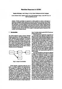
Figure 1: Example for a process space-based workflow execution
4
MIRKO SONNTAG, KATHARINA GÖRLACH, DIMKA KARASTOYANOVA, FRANK LEYMANN, MICHAEL REITER
In Figure 1 an example for a process space-based workflow execution is given. The workflow consists of three sequentially performed, interacting activities. The corresponding activity clients are distributed among two machines. There are two process spaces, one on each machine. Activity client 1 invokes a Web service (step 1. and 2.) and writes the response into process space 1 as data token A (3.). After that the activity is finished and the control is passed to activity client 2 via a control flow token in process space 1 (4., 5.). Activity client 2 uses the data in data token A to invoke a Web service (6., 7., 8.), writes the response into data token B in process space 2 (9.), and passes the control to activity client 3 via a control flow token in process space 2 (10.). Activity client 3 takes the control (11.), invokes a Web service with data from data token C (12., 13., 14.) and overwrites C with the response (15.). Distributed workflow execution based on a process space middleware has several advantages [7, 8] described in the following. With BPEL and WS-* the approach relies on standards and thus promises a high acceptance in the workflow community. The process space-based approach implements a natural way of distributing orchestration logic. There is neither a need for a workflow redesign (e.g. because of the introduction of additional message exchanges for coordination) nor for the usage of coordinating choreographies [11]. In contrast to centralized WfMSs, the navigator is no single point of failure anymore and the workload is distributed among all participants (i.e. activity clients). In case of strategic decisions of enterprises, workflow parts can easily be outsourced (or merged). There is no need to split (or merge) processes by hand, manually install the supporting middleware on all sides and deploy the workflow parts. Outsourcing and merging can be done with the process space-based middleware by simple reconfiguration steps. Since the orchestration logic can be executed on the same machine where the used service(s) reside, shipping data from and to services can be reduced. Furthermore, Web services can be bound locally without leaving the address space. The same result could be obtained with a centralized WfMS by relocating services to the side of the workflow system. But often this is not possible because other applications would break if they rely on services at specific locations or because service ownership forbids relocation.
3 RELATED WORK
This section presents related work in the fields of WfMSs especially designed for application in the area of scientific workflows and WfMSs enabling a distributed workflow execution.
3.1 Scientific WfMSs
Askalon [12] executes scientific workflows on top of Grid infrastructures based on the Globus Toolkit 4 (GT4) [13]. Typical application areas are theoretical chemistry and image processing. The centralized engine executes processes supplied in the Askalon-specific Abstract Grid Workflow Language (AGWL). AGWL models are independent of concrete resources. The scheduler maps workflow jobs on Grid resources. The resource manager deploys workflow jobs (i.e. software used by activities) on heterogeneous and decentralized Grid infrastructures. The GT4 middleware enables a dynamic binding of resources. Askalon uses workflow segmentation to cope with a changing IT environment. Particular workflow segments are bound to concrete resources during workflow execution if the control flow reaches the segment. However, workflow segmentation is not used for a decentralized workflow execution. Pegasus [14] is rather a workflow compiler than a scientific WfMS. It cooperates with the centralized workflow execution system Condor DAGMan [15]. Thus, Pegasus supports native DAGMan workflows and specific XML1-based formats. The workflows are templates without resource binding. Based on a template Pegasus determinates an execution strategy that can include workflow segmentation and data movements. Similar to Askalon, a late binding concept is provided on basis of workflow segmentation: Pegasus binds resources for a specific workflow segment which is then executed by Condor DAGMan. After that, Pegasus binds resources for the next segment, and so on. Additionally, Pegasus aims at reducing the amount of data produced during workflow execution. Therefore, it identifies and reuses existing data. In contrast to Askalon and Pegasus, our approach makes use of a decentralized workflow execution engine. Workflow segmentation is not used for late binding of resources but to identify workflow parts that can be deployed on different machines. Moreover, both approaches do not rely on the traditional workflow technology as described in [16] and by the WfMC2. Traditional workflow systems distinguish between process models and process instances, they are separated into a build time and a runtime environment, to name just a few properties. Swift [17] is a system to specify, execute and manage scientific and engineering workflows. Similar to Pegasus, Swift is does not execute workflows on its own but utilizes a centralized execution engine called Karajan [18]. Furthermore, it makes use of Falkon [19] for provisioning of resources and submission of tasks to resources. Swift employs a mechanism to access data sets independent of their physical representation and location with the help of XML Dataset Typing and Mapping (XDTM) [20]. A mapper accesses data sources and converts data into an XML form. It is also possible to write and update data sources. As opposed to Swift, we advocate a decentralized 1 2
eXtensible Markup Language Workflow Management Coalition, http://www.wfmc.org
PROCESS SPACE-BASED SCIENTIFIC WORKFLOW ENACTMENT
execution of scientific workflows. Moreover, the data reference mechanism we want to employ helps keeping massive data out of a workflow engine by using pointers instead of the complete data payload. The Swift XDTM approach transforms non-XML to XML data. Thus, the converted data is processed by the workflow engine. Additionally, the process space-based solution is built upon agreed-on standards like BPEL or WS-* and hence promises a higher user acceptance. Trident [21] is a commercial scientific WfMS built on traditional workflow technology. The contained workflow engine performs a centralized execution of processes. These processes are specified with a proprietary workflow language (eXtensible Object Markup Language, XOML), but can be transformed to and from BPEL. In contrast to Trident, our WfMS executes workflows in a distributed manner. To the best of our knowledge, Trident does not follow a data pointer concept as we foresee for our system.
5
with the help of data references that keep data not needed for process execution out of the workflow engine.
4 SCENARIO
With the scenario presented here we aim at illustrating the concepts in the subsequent discussion and it will serve as a basis for comparison of the centralized approach for scientific workflow execution and the distributed one. The presented scenario is a simulation of the diffusion of ink in water over a particular period of time. It consists of two major phases: first, the diffusion is calculated with the help of the finite element method (FEM) [27]; second, a procedure for visualizing the result of the simulation. The scenario description is interleaved with details on the typical infrastructure currently used for enacting it. 4.1 Simulation Step
3.2 Distributed WfMSs
Juliette [22] is a workflow system for the distributed execution of Little-JIL coordination models. Main parts of Juliette are an interpreter that coordinates the execution of workflows, and a resource manager to allocate resources and agents to perform the workflow steps. The interpreter can be split and distributed among the utilized resources. Each Little-JIL step thereby gets its own interpreter. These step interpreters (comparable to process space activity clients, see Section 2.4) are structured hierarchically: each step interpreter only reacts on events of its own step or of sub-steps, thus minimizing the global knowledge of the interpreters. By contrast, in our approach the activity clients do not know each other at all. They are completely decoupled with the help of process spaces, thus enabling more flexibility and robustness (e.g. exchanging of activity clients does not affect other clients). Osiris [23] is a distributed workflow engine that works on top of a peer-to-peer database system (hyper-database) that is dispersed among all participating nodes. During execution, process instance data is split and passed to the involved nodes in case of parallel paths. This requires a complex mechanism to join distributed data after parallel execution. In the process space-based WfMS merging of instance data is not needed. ADEPT [24] is a WfMS with support for ad-hoc changes at process runtime. There is a variant of ADEPT specifically designed for a decentralized execution of workflows, ADEPTdistribution [25, 26]. The aim of ADEPTdistribution is reducing the amount of data shipped between applications used in the workflow. The system allows static and dynamic distribution of tasks to participating nodes. Unlike the presented approaches, the process space solution relies on the traditional workflow technology and standardized languages as mentioned in Section 3.1. Another main difference is that the considered systems are not tailored to handling huge amounts of data as is often required in scientific workflows. We address this problem
The ink concentration in water can be expressed as differential equation in three space and one time dimension with particular conditions [28]. The simulation needs five general steps, as shown in Figure 3. Currently, the simulation can be performed using the Dune library. a widely used C++ library for the numerical solution of partial differential equations with mesh-based methods like finite elements (FE), finite volumes (FV), or finite differences (FD). Dune includes MPI3-support to enable the execution of simulations on parallel systems like supercomputers. MPI is a standard that describes the communication between distributed parts of an application. Dune can work with different types of meshes: 2D (see Figure 2), 3D, rectangle, cuboid, equidistant, with areas of greater accuracy, and more. In our previous work we exposed parts of Dune (without MPI-support) as WSs [29]. This allows us to (re)use Dune functions in service compositions, e.g. BPEL processes, seamlessly.
Figure 2: Non-equidistant 2D Dune-based Alberta mesh
Each step produces data the subsequent one relies on (see Figure 3). Create Mesh builds an equidistant FEM-mesh by field discretization. That means a field with an infinite number of points is transformed into a field with a finite number of points. The FEM-mesh represents the water the 3
Message Passing Interface, http://www.mpi-forum.org
6
MIRKO SONNTAG, KATHARINA GÖRLACH, DIMKA KARASTOYANOVA, FRANK LEYMANN, MICHAEL REITER
ink is injected into. This step often consumes a huge amount of main memory. Global Refine enhances the FEM mesh based on factors, such as geometry, simulation problem, initial or boundary condition. This results in a non-equidistant mesh that contains more points in areas of greater importance (e.g. the injection area). The required main memory is often substantially larger than after the Create Mesh step.
Figure 3: The Dune-based simulation process “ink diffusion in water”.
Allocate Vector describes the allocate function, which is a velocity field function that describes the ink diffusion in water. Initialize Mesh configures the FEM mesh with the initial and boundary conditions which are described with mathematical functions. The initial condition assigns every mesh point with the corresponding function value at starting time t0 (e.g. clear water without ink). The boundary condition assigns boundary mesh points with corresponding function values (e.g. “right” boundary must have the same value as the “left” boundary). Evolve solves the differential equation at a particular point in time with the help of numerical solvers based on linear algebra. The result is stored in a file. Evolve runs in a loop that is responsible for the time discretization of the differential equation. A typical start time is t0 = 0. After each run the next time step ti+1 is taken. The loop stops if the ink concentration in water is balanced or at a predefined time tend. The Evolve step requires a fast central processing unit (CPU). 4.2 Visualization Step
The simulation results need to be visualized. More precisely, typically visualization of only some parts of the simulated system is of importance, for example the ink concentration close to the boundaries. It depends on the goals of the scientific experiment and the evolution of the simulation run.
Figure 4: The basic visualization process with main steps Filtering, Mapping, and Rendering.
Figure 4 shows the basic steps needed to visualize the results. In the first step, Filtering, the received data is prepared for the following steps. More precisely the part of data is extracted that is interesting for the visualization, for example, the data that represents the ink concentration close to the boundaries. In the second step, Mapping, the extracted data is assigned to a particular representation. For instance, this can be done
with the help of a lookup table that assigns scalar values to dedicated color values or geometric objects. Finally, an image is generated from this representation in the Rendering step. Typically during rendering, specific instructions of the graphics processing unit (GPU) on a graphics board are executed. Therefore, the rendering service must be executed on a server where the required GPU exists and the used instructions are provided.
5 PROCESS SPACE-BASED SCIENTIFIC WORKFLOW ENACTMENT
In this section we present reasons for employing the process space-based solution for the application in the field of scientific workflows. Based on the example ink diffusion simulation (Section 4) we propose an appropriate process segmentation and distribution over participating machines for a concrete hardware and software infrastructure. Furthermore, we discuss the role of the deployment step in this context. Finally, we investigate whether the combination of the process space middleware with an approach of accessing data via pointers is beneficial for scientific workflows. 5.1 Why Process Space-based Workflow Execution?
The process space-based solution as outlined in [7] uses BPEL as workflow meta-model and thus promises a lot of advantages. For example, heterogeneous applications can be orchestrated since BPEL relies on WSs. Thus, even legacy software can be integrated by creating an appropriate WS wrapper. Decoupling workflow model parts with the help of process spaces opens up new possibilities for adaptability, a major requirement in the field of scientific workflows. The workflow model structure can be changed by inserting, replacing or deleting particular activity clients. Similarly, the control flow can be adapted by modifying the activity client templates that are used to retrieve associated tokens. That means it can be changed what tokens in which process space activity clients are waiting for and in which process space their tokens are put. The powerful mechanism of templates used to read tokens from process spaces makes it also possible to adapt single workflow instances instead of whole process models. Such adaptations can be realized even at runtime with the help of a control bus without a redeployment of the whole workflow model. An explicit channel creation like in message-oriented middleware is not needed [7]. Adaptation in centralized WfMSs is much more complex. The activities are hard-wired by means of an engine-internal format that cannot be changed without changing the engine internal implementation. A redeployment step would be necessary. Modifying workflows with running instances also constitutes the problem of migrating the instances to the new workflow model which may not be possible for all instances. In the process space approach instance migration is inherently done when the configuration of activity clients is changed.
PROCESS SPACE-BASED SCIENTIFIC WORKFLOW ENACTMENT
An important step in the methodology of the process space-based approach is mapping BPEL on EWFNs. This allows a formal analysis of workflows, such as a check of structural properties or the calculation of system invariants [30]. Furthermore, standard Petri net verification algorithms can be used to validate the correctness, soundness, and reachability of workflow graphs [31]. A first open-source prototype for activity clients and a process space implementation is being developed. The prototype can be used as basis for further development. 5.2 Set-up and Workflow Fragmentation
In this section we describe the infrastructure we use for the execution of the scenario introduced in Section 4 and suggest one fragmentation alternative for the distribution of process activities on this infrastructure. The set-up (see Figure 5) consists of two machines with specific properties. Machine 1 is created to handle expensive computer graphic calculation tasks. It contains a high-capacity GPU that supports OpenGL4. Software appropriate for visualizing simulation results is installed and provided as WS with three operations (filtering, mapping, and rendering). Machine 2 is specialized for compute-intensive tasks and therefore possesses a fast CPU and a huge main memory. The WSready variant of the Dune library [29] is installed to calculate partial differential equations. Several functions that the Dune library supports are made available as WSs.
Figure 5: Topology of scenario "ink concentration in water" in a process space environment
The workflow consists of three main parts: the preparation of the simulation (activities 1-4), the actual accomplishment of the simulation (activity 5), and the visualization of results (activities 6-8). The running numbers used as names of the activities also denotes their processing order. Activities 5-8 are surrounded by a shaded area, which stands for a while loop that models the repetition of these steps. The loop is controlled by activity W. After each loop step activity W decides whether to execute another iteration or not (the latter would mean to finish the workflow run). According to the supplied infrastructure the workflow is divided into two 4
Open Graphics Library – A specification of an interface for the development of 2D and 3D computer graphics.
7
segments: activities that are implemented by Dune functions and those activities that steer the visualization of results. That means the “cut” is done through the while loop. Obviously, activity clients for “Dune activities” get deployed on machine 2 that also hosts the Dune library. Similarly, clients for activities that realize the visualization are assigned to machine 1 where the visualization software is running. All activity clients are decoupled by process spaces. That means they interact indirectly via passing tokens to and reading tokens from process spaces. There are two process spaces, one for each machine. For that reason local access is in most cases sufficient to operate on the spaces. Only the clients for activities 5 and 8 need to pass tokens remotely to the process space that resides on the other machine (indicated by a dashed arrow). To increase the legibility of the figure it is assumed that the process spaces are used for both control and data tokens. 5.3 Deployment
The deployment of workflow models is strongly dependent on the used IT environment (i.e. available machines, data, and applications). Deploying workflows in a distributed process space environment requires a number of information: the segmented workflow in BPEL form, configured templates of activity clients, a deployment descriptor that maps workflow segments on participating machines, concrete service ports in case of a static service binding, criteria for service selection in case of a dynamic service binding, and properties of machines for the dynamic selection of resources. The decision about function or data shipping is a known aspect in the scientific community. The process space-based workflow enactment introduces another shipping type, a mechanism we call workflow shipping, i.e. the distribution of a workflow model over participating machines. Before distribution, a workflow model needs to be segmented into logically related units [10]. There are many forces driving the segmentation of workflow models, ranging from IT landscape to workflow logic [8]. For example, the availability and capabilities of machines, installed WSs, the location of data, or the dependencies between activities. After segmentation the particular activity clients and process spaces can be installed on chosen machines before workflow execution. This is a static binding case for which concrete addresses of machines are specified in the deployment descriptor. A key property of the scientific IT infrastructure is its changing nature. Resources may come and go dynamically so that running workflows can hardly rely on the availability of resources (i.e. WSs) specified at build- or deployment time, especially in the case of long-living workflows. With respect to such a changing IT environment activity clients and process spaces may also be dynamically shipped at runtime by the middleware. In this case, the deployment descriptor should not contain concrete addresses of resources but rather the properties used to discover and select them (e.g. CPU speed, HDD capacities, etc.). This way of declarative specification of resources to be used
8
MIRKO SONNTAG, KATHARINA GÖRLACH, DIMKA KARASTOYANOVA, FRANK LEYMANN, MICHAEL REITER
supports the dynamic binding to resources, which is more flexible in changing infrastructures but also has implications on the workflow execution in terms of performance and complexity. This is so because a resource manager has to query a directory of registered resources and select a resource that matches specified requirements (e.g. a GPU is needed). Furthermore, in some cases software has to be installed on a selected resource or data needs to be shipped. Note, that there are several binding strategies when specifying the binding of applications to services (as defined in [2]) and similarly, binding strategies are needed when applications like the simulation workflows need to be bound to hardware. Independent of the chosen binding strategy the major goals of workflow shipping should be to minimize remote interactions (activity to activity as well as activity to WS interactions) and to avoid passing huge amounts of data. This most often implies deploying activities at the site of associated WSs. The distribution of workflow parts on the IT landscape has implications on the explicit undeployment of workflow models: All activity clients as well as process spaces need to be uninstalled from all used servers. In case of a static binding these machines can simply be addressed using information from the deployment descriptor. In a dynamic workflow shipping scenario the undeployment is more complex especially if the workflow logic was adapted at runtime (e.g. new or moved activity clients). Service bus information is needed (e.g. a log file that recorded discovered and bound machines) to find used servers. A mechanism to ease the undeployment of a distributed workflow is the introduction of a lifetime management as known from Grid services [32]. Following the lifetime management approach installed activity clients and process spaces are associated a lifetime – duration or a deadline. If their lifetime expires, they are simply uninstalled. So-called “keep alive” messages can be utilized to negotiate a lifetime extension. That way, used machines implicitly garbage collect installed workflow parts that are not in use any more.
operations get slower. The latter is due to the expensive template matching mechanism on very large tokens. That means a process space can be overloaded quickly if it is used for the execution of scientific workflows. Therefore we propose the use of data references to avoid the transfer of large data sets to and from process spaces as well as eased internal operations. Figure 6 illustrates the approach. The transfer of a large or small data set is represented by a bold and fine arrow, respectively. Certainly, a data reference is represented by a fine arrow. In our example, the data that has to be visualized is successively processed by the services Filtering, Mapping and Rendering. The Filtering-service stores its result data in an available storage (3) that is extended by a Reference Resolution System (RRS) that is provided as WS. The RRS is responsible for the storage of data including the return of an appropriate reference, and the resolution of a reference including the return of the corresponding data. After the receipt of the data reference the Filtering-service sends the reference to the visualization process in response (4 and 5). The visualization process queries the process space for storing the reference as variable value and also passes a control token for the next activity (6). The Mapping-activity reads the control token as well as the data token with the data reference (7). It invokes the Mapping-service by passing the reference (8). Now the Mapping-service queries the RRS stated in the reference for the corresponding data and starts the processing (9 and 10). The result is passed to an RRS (can be the same one) which returns a new reference (11 and 12). The Mapping-service sends this result data reference to the activity in response (13). Afterwards the Rendering-activity and -service behave similarly.
5.4 Data References
Although the introduction of process space-based workflow enactment promises to decrease the number of remote interactions and to distribute the workload over several shoulders we can additionally improve the overall performance of workflow execution with the help of data references [5]. Since scientific workflows must cope with large data sets we determined the process spaces as remaining bottleneck. There can be multiple process spaces serving activity clients. However, similarly to a central navigator a single process space executes templates in a sequence. While parallel execution of activities or workflows a process space concurrently receives multiple read and write requests. That means activity clients have to wait until a process space completed previous tasks, especially if multiple clients are served in parallel (what is typical in scientific workflows). Additionally, if the size of data sets increases noticeable, the data transfer increases as well and the process space-internal
Figure 6: The use of data references in a workflow. When run on a process space-based enactment engine the large data sets are not stored into the process space.
Since the data that has to be visualized is not relevant for the process logic it can remain in the storages of participating services. A service transfers a reference to the process instead of a large data set. Therefore, the process space does not need to handle huge amounts of data which improves the overall performance of workflow execution. According to this, the bold arrows in Figure 6 occur merely on the right side where services and their storage are illustrated whereas the fine arrows are by the majority on the left side where process and process space are located. In BPEL a data reference is introduced as a special variable. The referencing is done by a WS-Addressing Endpoint Reference [33] that includes uniform resource
PROCESS SPACE-BASED SCIENTIFIC WORKFLOW ENACTMENT
identifiers for the eventual data location and the location of the appropriate RRS. There are different types of reference variables that additionally enable the use of context data in the process logic. A more detailed description of references in BPEL processes is given in [5].
6 DISCUSSION
As outlined in the previous section the decentralized workflow execution promises to meet particular requirements that arise especially in the area of scientific simulations. However, to emphasize the capabilities of the considerations the central and decentralized WfMS solutions are compared with the help of the scenario as introduced in Section 4. Each of the approaches is also combined with the concept of data references to achieve further improvements of the overall performance.
9
deployment mechanism in this setting is simple. On the other hand all interactions between WfMS and WSs are remote since the WSs are installed on machines 1 and 2. The data is handled by value. This results in frequently passing huge data sets remotely over the network. Furthermore, the navigator component of the engine acts as bottleneck. All instances of the workflow model are running on the same server (machine 3). Moreover, huge data items are processed by the engine (receiving and storing the data into corresponding databases of the WFMS) even if they are not needed for control flow evaluation. Machine 1
Machine 3
Machine 2
1
2
6
3
7
4
8
5
W
Figure 7: Legend for arrows and lines used in the following illustrations of the scenario.
The comparison bases upon four major aspects: the number of remote interactions, the size of the payload of a message to transmit, the size of the workload to be processed by the engine, and the complexity of the deployment mechanism. Figure 7 shows the legend that is useful to understand the illustrations of the particular approaches. In short, local interactions are denoted by dashed lines, remote ones by solid lines. Passing small data is indicated by thin lines, huge data by thick lines. Note the weight of the different edges. It can be seen as the effort to pass control or data between two components. We decided to set the costs of remote interactions twice as much as local interactions, moving huge data sets (e.g. of several mega bytes) is chosen to be eight times as expensive as small ones. However, the respective relations are selected restrictive. In fact, they may diverge even more. The illustrations contain up to three machines. Machine 1 (the visualization server) and 2 (the Dune server) feature the capabilities described in Section 5.1. The actual process spaces are omitted for readability. Machine 3 is the server for a centralized workflow engine. The workflow logic is also explained in Section 5.1. 6.1 Centralized Workflow Engine without Data References
Figure 8 illustrates the traditional approach that runs a central workflow engine on a single participant (machine 3). Therefore, the activities in the simulation workflow are coordinated internally by the workflow engine and no interaction with other machines is necessary. The
Figure 8: Control and data flow for the scenario “ink concentration in water” when using a centralized workflow execution.
Figure 9: Control and data flow for the scenario “ink concentration in water” when using a decentralized process space-based workflow execution. 6.2 Process Space-based Workflow Engine without Data References
In contrast to that, the process space-based approach (Figure 9) makes use of a decentralized WfMS. The activity clients are distributed among machines 1 and 2, locally to the used WSs. In our scenario, the optimal segmentation results in only local interactions between WfMS and WSs, i.e. the services and the activity clients run on the same machine. That means although the data is moved by value, less data is conveyed over the network. The engine-internal workload is carried by the participating servers 1 and 2 instead of a
10
MIRKO SONNTAG, KATHARINA GÖRLACH, DIMKA KARASTOYANOVA, FRANK LEYMANN, MICHAEL REITER
single machine. The major downside is the much more complex deployment mechanism (see Section 5.3). But indeed this complexity may have little or no impact on the runtime since it is a pre-runtime step for the most parts. Moreover, data and control flow tokens may need to be remotely shipped between activities. However, the applied segmentation strategy should aim to constrict these remote interactions (the example has only 3n remote interactions where n is the number of iterations in the loop).
drawbacks are the complex deployment mechanism, an additional RRS infrastructure, and an increased number of messages needed to resolve the data references. Machine 1
1
2
6.3 Centralized Workflow Engine and Data References
Figure 10 presents the scenario when applying data references and a central WfMS (machine 3). The WSs and appropriate RRSs are distributed among machine 1 and 2. Obviously, using the data by reference relieves the workflow engine of processing huge data sets if they are unnecessary for control flow evaluation (as in our scenario). Instead it is up to the WSs themselves to provision and store the actual data items with the help of RRSs. This fact can decrease the number of remote transmission of huge data amounts over the network depending on the location of RRSs (there is only one remote data provisioning operation per loop iteration in the scenario). The drawbacks are the need for an RRS infrastructure and additional wrapper for WSs [5] as well as more messages that are exchanged with respect to the overall system. The number of remote interactions between WfMS and WSs is as before. Moreover, the workflow engine is still a bottleneck that processes all instances of all deployed workflow models.
Figure 10: Control and data flow for the scenario “ink concentration in water” when using a centralized workflow execution and data references. 6.4 Process Space-based Workflow Engine and Data References
The approach of using both process space-based workflow enactment and data references is shown in Figure 11. This solution combines the benefits of both ideas. There are very few remote messages (5 per loop step), most of which transmit a small payload (only 1 message per loop with a huge payload). The process spaces are held free of large data tokens. The workload for workflow execution is shared among all participants. As mentioned earlier, the main
Machine 2
6
3 RRS
7
4
8
5
RRS
W
Figure 11: Control and data flow for the scenario “ink concentration in water” when using the concept of data references and a process space-based workflow enactment. 6.5 Comparison
In order to compare all of the approaches presented above all weighted arrows (including the control flow) are counted and added up for all four approaches according to the scenario. The respective result is an indicator about how expensive the considered solution is (the higher the score, the more expensive the solution). We assume three iterations of the while loop to keep the numbers simple. Table 1 gives an overview of the results. Obviously, the traditional approach is the most expensive one for our scenario. This is due to the moving of large data over the network (28 times). That means this approach is especially useful if no huge data items are exchanged or if the workflow logic is confidential. The decentralized workflow enactment achieves better results. It is a relatively cheap solution because of its few remote messages (6 times control flow and 3 times huge data flow). But the process spaces might get into trouble when handling tokens with a size of several mega bytes or larger. This solution should be applied if there are many remote interactions between Table 1: Estimated effort/costs for the execution of the scenario “ink concentration in water” according to the four considered solutions. Weight No Refs, No PS Σ # CF (local) 1 19 19 CF (remote) 2 DF (WF‐int., local, small) 1 DF (WF‐int., remote, small) 2 DF (WF‐int., local, huge) 8 13 104 DF (WF‐int., remote, huge) 16 DF (WF‐ext., local, small) 1 DF (WF‐ext., remote, small) 2 4 8 DF (WF‐ext., local, huge) 8 DF (WF‐ext., remote, huge) 16 28 448 579 Total points
No Refs, With Refs, With Refs, with PS no PS with PS Σ Σ Σ # # # 13 13 19 19 13 13 6 12 6 12 13 13 10 10 3 6 10 80 3 48 4 4 25 25 57 57 35 70 3 6 28 224 25 200 25 200 3 48 3 48 381 375 352
CF = Control Flow, DF = Data Flow, PS = Process Space, Refs = Data References, WF‐int. = Workflow internal, WF‐ext. = Workflow external
PROCESS SPACE-BASED SCIENTIFIC WORKFLOW ENACTMENT
WfMS and WSs, especially if many activities address the same server. The message payload should be relatively small. The data references approach in a centralized WfMS is slightly cheaper but needs a lot of remote messages (35 with small payload and 3 with huge payload). This means that this setting can be applied if the number of remote messages is small but the message payload is huge. However, the cheapest solution results from the combination of data references with a process space-based WfMS. This is achieved by fewer remote interactions as opposed to the data references only setting. Again, increasing the penalty for remote messages will negatively affect the result compared to the process space-based approach without data references. The strongest argument for the last solution is that the process spaces are not cluttered up with huge amounts of data and data is not moved from the local data storages of services to the spacebased middleware used by the engine and vice versa. This cannot be reflected in the table since it only accounts for messages being sent. The approach is applicable in scenarios where many messages with large payload are remotely exchanged. The results of the comparison are based on our assumptions about the weights of each of the considered factors and may slightly change should the weight coefficients be modified. More precise results for this comparison can only be collected through performance measurements, which are planned activity in our future work.
7 CONCLUSION AND FUTURE WORK
In this paper we investigated the applicability of the process space-based workflow enactment for the scientific domain. There are particular factors that influence the performance of scientific IT applications, such as distributed resources with different capabilities, or huge data sets that are created and processed. We argue that the overall performance of an IT system in this context can be increased with the help of a decentralized workflow execution using process spaces. Moreover, we combine the approach with the concept of BPEL data references to prevent process spaces from becoming a bottleneck when handling large data tokens relevant for most scientific scenarios. A comparison between the centralized and process space-based workflow execution with and without data references based on a scenario illustrated the potential of the solution. In settings where many messages are exchanged remotely it decreases the network traffic dramatically. Especially the capabilities with respect to adaptability promise additional benefit for scientists. However, there are challenges that need further investigation and that drive our future work. For instance, the deployment and undeployment of activity clients and process spaces at runtime has to be improved to accommodate the dynamic characteristics of the scientific infrastructures. Additionally, we need sophisticated segmentation algorithms that meet the requirements of a
11
scientific IT landscape. Finally, there is the challenge of developing provenance and recovery mechanisms in a workflow environment with no global state. There is still much work to be done in the area of modeling scientific workflows and the automated optimal segmentation of workflows across the infrastructure in a user-friendly manner. ACKNOWLEDGEMENT
The work presented in this paper has been funded by the DFG Cluster of Excellence Simulation Technology5 (EXC310).
REFERENCES 1
S. J. Mullender (ed.): “Distributed Systems”. 2nd ed., ser. ACM Press frontier series, New York, NY: ACM Press, 1993. 2 S. Weerawarana, F. Curbera, F. Leymann, T. Storey, and D. F. Ferguson: “Web Services Platform Architecture: SOAP, WSDL, WS-Policy, WS-Addressing, WS-BPEL, WSReliable Messaging, and More”. Prentice-Hall, 2005. 3 OASIS: “Web Services Business Process Execution Language Version 2.0”, 2007. 4 A. Akram, D. Meredith, and R. Allan: “Evaluation of BPEL to Scientific Workflows”. In: Cluster Computing and the Grid (CCGrid). IEEE Computer Society, 2006, pp. 269–274. 5 M. Wieland, K. Görlach, and D. Schumm: “Towards Reference Passing in Web Service and Workflow-based Applications”. In. 13th IEEE Enterprise Distributed Object Conference (EDOC), 2009. 6 D. Gelernter: “Generative Communication in Linda”. In: ACM Transactions on Programming Languages and Systems, 7(1):80–112, 1985. 7 D. Wutke, D. Martin, and F. Leymann: “Model and Infrastructure for Decentralized Workflow Enactment”. In: 23rd ACM Symposium on Applied Computing (SAC2008), 2008. 8 D. Martin, D. Wutke, and F. Leymann: “A Novel Approach to Decentralized Workflow Enactment”. In: 12th IEEE EDOC Conference, 2008. 9 D. Martin, D. Wutke, and F. Leymann: “EWFN - a Petri Net Dialect for Tuplespace-based Workflow Enactment”. In: 15th German Workshop on Algorithms and Tools for Petri Nets (AWPN 2008), N. Lohmann and K. Wolf, Eds., 2008. 10 D. Wutke, D. Martin, and F. Leymann: “Tuplespace-based Infrastructure for Decentralized Enactment of BPEL Processes”. In: 9. Internationale Tagung Wirtschaftsinformatik: Business Services, Konzepte, Technologien, Anwendungen (WI 2009), 2009. 11 G. Decker, O. Kopp, F. Leymann, M. Weske: “BPEL4Chor: Extending BPEL for Modeling Choreographies”. In: IEEE Computer Society (eds.): Proceedings of the IEEE 2007 International Conference on Web Services (ICWS 2007), Salt Lake City, Utah, USA, July 2007. 12 T. Fahringer, R. Prodan, R. Duan, J. Hofer, F. Nadeem, F. Nerieri, S. Podlipnig, J. Qin, M. Siddiqui, H.-L. Truong, A. Villazon, and M. Wieczorek: “Askalon: A Development and Grid Computing Environment for Scientific Workflows”, In: Workflows for e-Science: Scientific Workflows for Grids, I. J. Taylor, E. Deelman, D. B. Gannon, and M. Shields (Eds.), Springer, 2007, pp. 451–471.
5
http://www.simtech.uni-stuttgart.de
12 13 14
15 16 17
18
19 20 21 22
23
24 25
26 27 28
29 30 31 32 33
MIRKO SONNTAG, KATHARINA GÖRLACH, DIMKA KARASTOYANOVA, FRANK LEYMANN, MICHAEL REITER I. Foster: “Globus Toolkit Version 4: Software for Serviceoriented Systems”, In: Journal of Computer Science and Technology, vol. 21, no. 4. Springer, 2006. E. Deelman, J. Blythe, Y. Gil, C. Kesselmann, G. Mehta, S. Patil, M.-H. Su, K. Vahi, and M. Livny: “Pegasus: Mapping Scientific Workflows onto the Grid”. In: Lecture Notes in Computer Science (Second European AcrossGrids Conference), vol. 3165/2004. Springer, 2004, pp. 11–20. Lovas et al., “Workflow support for complex grid applications: Integrated and portal solutions”. In: Grid Computing. Springer, 2004. F. Leymann and D. Roller: “Production Workflows: Concepts and Techniques”. Prentice Hall, 2000. Y. Zhao, M. Hategan, B. Clifford, I. Foster, G. v. Laszewski, I. Raicu, T. Stef-Praun, and M. Wilde: “Swift: Fast, Reliable, Loosely Coupled Parallel Computation”. In: IEEE International Workshop on Scientific Workflows, 2007, Salt Lake City, Utah, U.S.A. G. v. Laszewski, M. Hategan, and D. Kodeboyina: “Java CoG Kit Workflow”. In: I. J. Taylor, E. Deelman, D. B. Gannon, and M. Shields (eds.): Workflows for eScience, 2007, pp. 340356. I. Raicu, Y. Zhao, C. Dumitrescu, I. Foster, and M. Wilde: “Falkon: a Fast and Light-weight tasK executiON framework”. In: IEEE/ACM Supercomputing, 2007. L. Moreau, Y. Zhao, I. Foster, J. Voeckler, and M. Wilde: “XDTM: XML Data Type and Mapping for Specifying Datasets”. In: European Grid Conference, 2005. R. S. Barga, J. Jackson, N. Araujo, D. Guo, N. Gautam, and Y. Simmhan: “The Trident Scientific Workflow Workbench”. In: IEEE International Conference on eScience, 2008. A. G. Cass, B. S. Lerner, E. K. McCall, L. J. Osterweil, and A. Wise: “Logically central, physically distributed control in a process runtime environment”. Technical Report 99-65, University of Massachusetts at Amherst, Nov. 1999. C. Schuler: “Verteiltes Peer-to-Peer-Prozessmanagement – Die Realisierung einer Hyperdatenbank”. PhD thesis, Eidgenössische Technische Hochschule Zürich, Switzerland, 2004. M. Reichert and P. Dadam: “ADEPTflex – Supporting Dynamic Changes of Workflows Without Losing Control”. In: Journal of Intelligent Information Systems, 10(2), 1998. T. Bauer and P. Dadam: “A Distributed Execution Environment for Large-Scale Workflow Management Systems with Subnets and Server Migration”. In: Proceedings of the 2nd Conference on Cooperative Information Systems (Coopis), 1997. T. Bauer and P. Dadam: “Efficient Distributed Workflow Management Based on Variable Server Assignments”. In: Lecture Notes in Computer Science, Springer-Verlag, 2000. O. C. Zienkiewicz and R. L. Taylor: “The Finite Element Method”, 4th ed. McGraw-Hill, 1989, vol. 1. P. Bastian, M. Blatt, A. Dedner, C. Engwer, R. Klöfkorn, M. Nolte, M. Ohlberger, and O. Sander: “The Distributed and Unified Numerics Environment (DUNE) Grid Interface HowTo”, 2009, version 1.3. J. Rutschmann: “Generisches Web Service Interface um Simulationsanwendungen in BPEL-Prozesse einzubinden”. Diploma Thesis No. 2895, University of Stuttgart, 2009. C. Ouyang: “WofBPEL: A Tool for Automated Analysis of BPEL Processes”. In: Proceedings of the ICSOC, 2005. K. Jensen: “Coloured Petri Nets, Volume 1: Basic Concepts”. Monographs in Theoretical Computer Science, SpringerVerlag, 1992. I. Foster and C. Kesselmann: “The Grid 2: Blueprint for a New Computing Infrastructure”. Morgan Kaufmann, 2004. W3C: “Web services addressing 1.0 - core”, 2006, W3C Recommendation. Available: http://www.w3.org/TR/ws-addr-core/
Reference to this paper should be made as follows: Mirko Sonntag, Katharina Görlach, Dimka Karastoyanova, Frank Leymann, Michael Reiter (2010) ‘Process Space-based Scientific Workflow Enactment’, International Journal of Business Process Integration and Management, Special Issue on Scientific Workflows, Vol. X, No. X, pp.000–000.